EP0021909A1 - Stabilisierter Hyperfrequenzoszillator mit Frequenzumsetzung und seine Festkörperausführung - Google Patents
Stabilisierter Hyperfrequenzoszillator mit Frequenzumsetzung und seine Festkörperausführung Download PDFInfo
- Publication number
- EP0021909A1 EP0021909A1 EP80400787A EP80400787A EP0021909A1 EP 0021909 A1 EP0021909 A1 EP 0021909A1 EP 80400787 A EP80400787 A EP 80400787A EP 80400787 A EP80400787 A EP 80400787A EP 0021909 A1 EP0021909 A1 EP 0021909A1
- Authority
- EP
- European Patent Office
- Prior art keywords
- frequency
- section
- circuit
- oscillator according
- microwave oscillator
- Prior art date
- Legal status (The legal status is an assumption and is not a legal conclusion. Google has not performed a legal analysis and makes no representation as to the accuracy of the status listed.)
- Granted
Links
- 239000007787 solid Substances 0.000 title claims description 6
- 238000006243 chemical reaction Methods 0.000 title claims description 3
- 238000010586 diagram Methods 0.000 description 6
- 238000009795 derivation Methods 0.000 description 5
- 230000010355 oscillation Effects 0.000 description 5
- 239000003990 capacitor Substances 0.000 description 2
- 230000006641 stabilisation Effects 0.000 description 2
- 238000011105 stabilization Methods 0.000 description 2
- 230000006978 adaptation Effects 0.000 description 1
- 230000003321 amplification Effects 0.000 description 1
- 238000009434 installation Methods 0.000 description 1
- 239000000463 material Substances 0.000 description 1
- 238000000034 method Methods 0.000 description 1
- 238000012986 modification Methods 0.000 description 1
- 230000004048 modification Effects 0.000 description 1
- 238000003199 nucleic acid amplification method Methods 0.000 description 1
- 238000010248 power generation Methods 0.000 description 1
- 230000002787 reinforcement Effects 0.000 description 1
- 230000000087 stabilizing effect Effects 0.000 description 1
- 230000017105 transposition Effects 0.000 description 1
Images

Classifications
-
- H—ELECTRICITY
- H03—ELECTRONIC CIRCUITRY
- H03B—GENERATION OF OSCILLATIONS, DIRECTLY OR BY FREQUENCY-CHANGING, BY CIRCUITS EMPLOYING ACTIVE ELEMENTS WHICH OPERATE IN A NON-SWITCHING MANNER; GENERATION OF NOISE BY SUCH CIRCUITS
- H03B9/00—Generation of oscillations using transit-time effects
- H03B9/12—Generation of oscillations using transit-time effects using solid state devices, e.g. Gunn-effect devices
- H03B9/14—Generation of oscillations using transit-time effects using solid state devices, e.g. Gunn-effect devices and elements comprising distributed inductance and capacitance
- H03B9/145—Generation of oscillations using transit-time effects using solid state devices, e.g. Gunn-effect devices and elements comprising distributed inductance and capacitance the frequency being determined by a cavity resonator, e.g. a hollow waveguide cavity or a coaxial cavity
- H03B9/146—Generation of oscillations using transit-time effects using solid state devices, e.g. Gunn-effect devices and elements comprising distributed inductance and capacitance the frequency being determined by a cavity resonator, e.g. a hollow waveguide cavity or a coaxial cavity formed by a disc, e.g. a waveguide cap resonator
-
- H—ELECTRICITY
- H03—ELECTRONIC CIRCUITRY
- H03F—AMPLIFIERS
- H03F7/00—Parametric amplifiers
- H03F7/04—Parametric amplifiers using variable-capacitance element; using variable-permittivity element
Definitions
- the invention relates to a stabilized oscillator for radio waves in the microwave field.
- the oscillator of the invention has a general structure which recalls that of parametric amplifiers. It makes it possible to obtain a high frequency wave stabilized on a frequency f o ..
- Parametric amplifiers include three essential parts, corresponding to three frequencies f s , f p and f which cooperate with one another as will be recalled.
- a first source of frequency f s is assisted by a second source at the pump frequency f, placed in parallel with it at the terminals of a non-linear, or parametric capacitance, the value C (V) of which varies with the voltage applied to its limits.
- the frequency f is generally much higher than the frequency f s of the signal, and the power level at this frequency f p much higher than that of the signal on f s .
- the source at the pump frequency f p modifies the impedance at the frequency f s and allows amplification on this frequency.
- the frequency f o is itself much higher than the frequency f s .
- the same arrangement is used in the invention for another purpose, that of stabilizing an oscillation frequency.
- the frequency stabilized in the device of the invention is the frequency f.
- this arrangement makes it possible to employ, at the stabilization of the frequency f, elements resonating at a frequency f s substantially lower and capable, therefore, of a better coefficient of quality.
- the frequency f o is obtained by transposition, or conversion, of frequency, with a noise / signal ratio very close to that which would be obtained at a frequency stabilized directly by the circuit with a high quality coefficient.
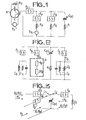
- FIG. 1 gives the diagram of a parametric amplifier, known in the art.
- a source called a pump supplies a voltage of large amplitude of frequency f p across the terminals of the capacitance C (V), the value of which depends on the voltage which is applied between its reinforcements.
- An incident signal, at frequency f is supplied by a generator V s mounted at the input of one of the channels, 1 of a circulator A, the other two channels of which open one, item 2, on the capacitance C (V) above, and the other, item 3, on a load resistor R s .
- the wave at frequency f s takes channel 2 towards the capacity C (V), lower bent arrow; it is amplified by reflection towards track 3 which it borrows on the return, upper bent arrow, towards the load resistance R.
- a signal is generated at the frequency f o connected to the previous frequencies f p and f s as already indicated.
- the frequency fp is commonly in a parametric amplifier from several times to several tens of times, the frequency f; the gain in power is commonly of the order of 10 to 15 decibels.
- R o and R p denote, respectively, the series loss resistance of the capacitance C (V) and of the derivations at the frequencies fo and f p ; the rectangles represent bandpass filters at different frequencies.
- the power available on the frequency f o remains unused.
- the same device can be used to generate high frequency power used on the frequency f o . For this, certain impedance conditions must be met.
- a power is available on the frequency f, created by combination of the frequencies f s and f p , which can be extracted in a load of use belonging to a resonant circuit, mounted in the branch at the frequency f o and tuned to this frequency; Z o represents the impedance of this load.
- the generator of the pump frequency f p is a dipole element with negative resistance.
- the negative resistance dipole is integrated into the device and its operating conditions determined by all of the parameters of the three leads; the gain in particular, in the branch f, is sufficiently high to ensure the oscillation of the system.
- the signs to which the powers are assigned indicate whether there is power consumption or generation in the corresponding circuit.
- Two examples of series of frequency values achievable with the device of the invention are: the first with a dielectric resonator, the second with a surface elastic wave resonator on f s .
- the frequency f can be of the order of 20 times the frequency f s .
- the pump bypass is equivalent to a circuit whose quality coefficient, or overvoltage, is of the same order as that of the low frequency circuit f s , whatever the ratio f D / f S , that is to say even for pump frequencies very far from the frequency f.
- the conditions to be observed to obtain the necessary level in the pump circuit that is to say the conditions for charging the dipole with negative resistance, are similar to those to be achieved for a dipole mounted on a single branch, with a frequency unique operating.
- the oscillator of the invention finds one of its applications in radio reception installations, in particular radar, as a local source.
- the frequency f can be tuned by variation of the reactance X D of the dipole with negative pump resistance (Xp in equation (I)), without any correlative modification of the quality coefficient of the frequency circuit f.
- the device of the invention is capable of being produced from components in the solid state. Two examples are given below.
- the high-overvoltage resonant circuit at frequency f s is then a dielectric resonator, the pump source a Gunn or avalanche diode.
- the nonlinear element it consists, in the case of a capacitor, of a diode in the solid state with variable capacitance, consisting of a diode polarized in reverse by an adjustable direct voltage which fixes the extent of its deserted area.
- the three leads f, f and f D consist of three waveguide sections of the types used in the microwave technique.
- the dielectric resonator is designated by the letter r, the variable capacity diode by the letter V and the negative resistance diode by the letter A, Gunn diode in the example.
- the mounting of the elements in the waveguide sections takes place according to the known practice in this matter.
- the waveguides, of rectangular section, are represented in section by the median plane parallel to their short sides.
- F 1 and F 2 respectively designate a band-cut filter and a band-pass filter; the hatched rectangle is a short circuit that closes the horizontal guide to one of its ends, the other of which outputs on the load impedance not shown, Z at the frequency f, under the usual adaptation conditions.
- the guide is cut off by the frequency f D in its part to the right of F 2 .
- the avalanche diode plays both the role of source at the pump frequency and of parametric inductance.
- the variable capacitance diode V is simply used for electronic frequency tuning.
- Resonators r are cylinders, made of one of the materials usually used for this purpose.
Landscapes
- Engineering & Computer Science (AREA)
- Power Engineering (AREA)
- Inductance-Capacitance Distribution Constants And Capacitance-Resistance Oscillators (AREA)
- Stabilization Of Oscillater, Synchronisation, Frequency Synthesizers (AREA)
Applications Claiming Priority (2)
| Application Number | Priority Date | Filing Date | Title |
|---|---|---|---|
| FR7915452A FR2459582A1 (fr) | 1979-06-15 | 1979-06-15 | Oscillateur pour hyperfrequences stabilise, a conversion de frequence, et sa realisation a l'etat solide |
| FR7915452 | 1979-06-15 |
Publications (2)
| Publication Number | Publication Date |
|---|---|
| EP0021909A1 true EP0021909A1 (de) | 1981-01-07 |
| EP0021909B1 EP0021909B1 (de) | 1985-08-07 |
Family
ID=9226705
Family Applications (1)
| Application Number | Title | Priority Date | Filing Date |
|---|---|---|---|
| EP80400787A Expired EP0021909B1 (de) | 1979-06-15 | 1980-06-03 | Stabilisierter Hyperfrequenzoszillator mit Frequenzumsetzung und seine Festkörperausführung |
Country Status (4)
| Country | Link |
|---|---|
| US (1) | US4380744A (de) |
| EP (1) | EP0021909B1 (de) |
| DE (1) | DE3070950D1 (de) |
| FR (1) | FR2459582A1 (de) |
Families Citing this family (4)
| Publication number | Priority date | Publication date | Assignee | Title |
|---|---|---|---|---|
| US4839832A (en) * | 1988-03-14 | 1989-06-13 | The Charles Stark Draper Laboratory, Inc. | Negative resistance device local extremum seeking circuit |
| US5373263A (en) * | 1993-03-22 | 1994-12-13 | The United States Of America As Represented By The United States National Aeronautics And Space Administration | Transverse mode electron beam microwave generator |
| US6313587B1 (en) | 1998-01-13 | 2001-11-06 | Fusion Lighting, Inc. | High frequency inductive lamp and power oscillator |
| US6137237A (en) | 1998-01-13 | 2000-10-24 | Fusion Lighting, Inc. | High frequency inductive lamp and power oscillator |
Citations (1)
| Publication number | Priority date | Publication date | Assignee | Title |
|---|---|---|---|---|
| FR2349996A1 (fr) * | 1976-04-26 | 1977-11-25 | Nippon Telegraph & Telephone | Oscillateur uhf a blocage par injection du type a l'etat solide |
Family Cites Families (4)
| Publication number | Priority date | Publication date | Assignee | Title |
|---|---|---|---|---|
| US3510800A (en) * | 1967-07-24 | 1970-05-05 | Hitachi Ltd | Negative resistance oscillator stabilized with fundamental and harmonic frequency cavity resonators |
| GB1413317A (en) * | 1971-12-28 | 1975-11-12 | Fujitsu Ltd | Solid state oscillators |
| US3735286A (en) * | 1972-05-01 | 1973-05-22 | Associates V | Varactor tuned coaxial cavity negative resistance diode oscillator |
| DE2826767C3 (de) * | 1978-06-19 | 1981-12-17 | Licentia Patent-Verwaltungs-Gmbh, 6000 Frankfurt | Schaltungsanordnung zur Erzeugung und stabilen Verstärkung breitbandiger RF-Signale |
-
1979
- 1979-06-15 FR FR7915452A patent/FR2459582A1/fr active Granted
-
1980
- 1980-06-03 EP EP80400787A patent/EP0021909B1/de not_active Expired
- 1980-06-03 DE DE8080400787T patent/DE3070950D1/de not_active Expired
- 1980-06-12 US US06/158,864 patent/US4380744A/en not_active Expired - Lifetime
Patent Citations (1)
| Publication number | Priority date | Publication date | Assignee | Title |
|---|---|---|---|---|
| FR2349996A1 (fr) * | 1976-04-26 | 1977-11-25 | Nippon Telegraph & Telephone | Oscillateur uhf a blocage par injection du type a l'etat solide |
Non-Patent Citations (3)
| Title |
|---|
| 1974 IEEE INTERNATIONAL SOLID-STATE CIRCUITS CONFERENCE, 15 Fevrier 1974, New York US SATOH et al.: "Stabilized oscillator using a temperature-stable dielectric resonator", pages 184-185 * Figure 1 * * |
| IEEE TRANSACTIONS ON MICROWAVE THEORY AND TECHNIQUES, Vol. 24, No. 3, Mars 1976 New York US NANBU: "A stabilized MIC oscillator using a germanium avalanche diode" pages 151-153 * Page 152, colonne de gauche, ligne 14, colonne de droite, ligne 8; figures 1,2 * * |
| IEEE TRANSACTIONS ON MICROWAVE THEORY AND TECHNIQUES, Vol. MTT-19, No. 5, Mai 1971 New York US OKEAN et al.: "Integrated parametric amplifier module with selfcontained solid-state pump source" pages 491-493 * Page 491, ligne 21 - page 492, colonne de droite, ligne 3; figure 2 * * |
Also Published As
| Publication number | Publication date |
|---|---|
| EP0021909B1 (de) | 1985-08-07 |
| FR2459582B1 (de) | 1984-02-03 |
| US4380744A (en) | 1983-04-19 |
| DE3070950D1 (en) | 1985-09-12 |
| FR2459582A1 (fr) | 1981-01-09 |
Similar Documents
| Publication | Publication Date | Title |
|---|---|---|
| EP0283074B1 (de) | Hyperfrequenz-Mischer | |
| EP0048189B1 (de) | Transistor-Oszillator mit dielektrischem Resonator, welcher ihm maximale Stabilität und minimales Rauschen im sehr hohen Frequenzbereich verleiht | |
| EP1909386A1 (de) | Negativer kapazitiver Stromkreis für Hochfrequenzanwendungen | |
| EP0012093A1 (de) | Verteilter Mikrowellenverstärker und diesen Verstärker enthaltende Verstärkervorrichtung | |
| EP0300524A1 (de) | Regelbares Dämpfungsglied zum Einfügen zwischen einem Emitterkreis und einem Belastungskreis | |
| EP0021909B1 (de) | Stabilisierter Hyperfrequenzoszillator mit Frequenzumsetzung und seine Festkörperausführung | |
| EP0087841B1 (de) | Anwendung eines Feldeffekttransistors mit zwei Gattern und zwischenliegender Leiterbahn, zum Sperren eines Frequenzbandes | |
| EP0596562B1 (de) | Vorrichtung mit einer Schaltung zum Verarbeiten eines Wechselsignals | |
| EP0120756B1 (de) | Hochfrequenzbandpassverstärker mit einem eine anpassbare Impedanz enthaltenden Oszillator | |
| EP0563370A1 (de) | Halbleitergerät mit mehreren funktionellen Blöcken, jeder Block mit einer Gleichspannungsverteilungsleitung. | |
| EP0794622A1 (de) | Funkempfänger mit reduzierter Strahlung | |
| EP0203663B1 (de) | Hyperfrequenzleistungsoszillator, der in einem grossen Frequenzgebiet linear moduliert ist | |
| EP0219366A1 (de) | Generator für Oberwellen hoher Ordnung | |
| EP0139583B1 (de) | Quarzoszillator für sehr hohe Frequenzen | |
| EP0231391A1 (de) | Durch einen dielektrischen resonator gesteuerter oszillator mit frequenzvervielfachung. | |
| EP0143041A2 (de) | Einrichtung zur Kompensation der Beschleunigungsempfindichkeit eines Oszillators | |
| EP0258076A1 (de) | Mikrowellen-Quarzoszillator | |
| EP0009435A2 (de) | Stabilisierte Hochfrequenz-Festkörperoszillator-Vorrichtung | |
| EP1271767A1 (de) | Vorrichtung zur Einstellung der Vorspannung für eine breitbandige elektronische Vorrichtung und zugehöriger Verstärker | |
| EP0361295B1 (de) | Mikrowellen-Frequenzteiler | |
| FR2586872A1 (fr) | Convertisseur hyperfrequence-radiofrequence monolithique. | |
| EP0619645A1 (de) | Anordnung mit einer symmetrischen und linearisierten Antwort, eine solche Anordnung verwendender Oszillator, und einen solchen Oszillator verwendender Fernsteuersender | |
| EP0040998A1 (de) | Oszillator mit verlängertem Wechselwirkungsbereich | |
| FR2597680A1 (fr) | Dispositif semiconducteur incluant un circuit amplificateur-melangeur distribue. | |
| EP0066326A1 (de) | Gleichspannungsversorgungsvorrichtung aktiver Hochfrequenzelemente |
Legal Events
| Date | Code | Title | Description |
|---|---|---|---|
| PUAI | Public reference made under article 153(3) epc to a published international application that has entered the european phase |
Free format text: ORIGINAL CODE: 0009012 |
|
| AK | Designated contracting states |
Designated state(s): DE GB NL |
|
| 17P | Request for examination filed |
Effective date: 19810121 |
|
| GRAA | (expected) grant |
Free format text: ORIGINAL CODE: 0009210 |
|
| AK | Designated contracting states |
Designated state(s): DE GB NL |
|
| REF | Corresponds to: |
Ref document number: 3070950 Country of ref document: DE Date of ref document: 19850912 |
|
| PLBE | No opposition filed within time limit |
Free format text: ORIGINAL CODE: 0009261 |
|
| STAA | Information on the status of an ep patent application or granted ep patent |
Free format text: STATUS: NO OPPOSITION FILED WITHIN TIME LIMIT |
|
| 26N | No opposition filed | ||
| PGFP | Annual fee paid to national office [announced via postgrant information from national office to epo] |
Ref country code: GB Payment date: 19930520 Year of fee payment: 14 |
|
| PGFP | Annual fee paid to national office [announced via postgrant information from national office to epo] |
Ref country code: DE Payment date: 19930527 Year of fee payment: 14 |
|
| PGFP | Annual fee paid to national office [announced via postgrant information from national office to epo] |
Ref country code: NL Payment date: 19930630 Year of fee payment: 14 |
|
| PG25 | Lapsed in a contracting state [announced via postgrant information from national office to epo] |
Ref country code: GB Effective date: 19940603 |
|
| PG25 | Lapsed in a contracting state [announced via postgrant information from national office to epo] |
Ref country code: NL Effective date: 19950101 |
|
| GBPC | Gb: european patent ceased through non-payment of renewal fee |
Effective date: 19940603 |
|
| NLV4 | Nl: lapsed or anulled due to non-payment of the annual fee | ||
| PG25 | Lapsed in a contracting state [announced via postgrant information from national office to epo] |
Ref country code: DE Effective date: 19950301 |