EP0021971B1 - Verfahren zur Kontrolle des Ablesens einer Tonaufnahme bei Zuhilfenahme eines zu dieser Aufnahme zusätzlichen Signals - Google Patents
Verfahren zur Kontrolle des Ablesens einer Tonaufnahme bei Zuhilfenahme eines zu dieser Aufnahme zusätzlichen Signals Download PDFInfo
- Publication number
- EP0021971B1 EP0021971B1 EP80400872A EP80400872A EP0021971B1 EP 0021971 B1 EP0021971 B1 EP 0021971B1 EP 80400872 A EP80400872 A EP 80400872A EP 80400872 A EP80400872 A EP 80400872A EP 0021971 B1 EP0021971 B1 EP 0021971B1
- Authority
- EP
- European Patent Office
- Prior art keywords
- signal
- recording
- auxiliary signal
- auxiliary
- information
- Prior art date
- Legal status (The legal status is an assumption and is not a legal conclusion. Google has not performed a legal analysis and makes no representation as to the accuracy of the status listed.)
- Expired
Links
- 238000000034 method Methods 0.000 title claims abstract description 17
- 238000012546 transfer Methods 0.000 claims description 10
- 230000004044 response Effects 0.000 claims description 5
- 238000000926 separation method Methods 0.000 claims description 2
- 230000005055 memory storage Effects 0.000 claims 3
- 230000002093 peripheral effect Effects 0.000 claims 2
- 230000003213 activating effect Effects 0.000 claims 1
- 238000012795 verification Methods 0.000 claims 1
- 238000001514 detection method Methods 0.000 abstract description 9
- 238000012544 monitoring process Methods 0.000 abstract 2
- 230000033458 reproduction Effects 0.000 description 17
- 238000012937 correction Methods 0.000 description 4
- 238000001228 spectrum Methods 0.000 description 3
- 238000010586 diagram Methods 0.000 description 2
- 238000007792 addition Methods 0.000 description 1
- 230000002238 attenuated effect Effects 0.000 description 1
- 238000013475 authorization Methods 0.000 description 1
- 230000008859 change Effects 0.000 description 1
- 230000000694 effects Effects 0.000 description 1
- 238000001914 filtration Methods 0.000 description 1
- 238000012986 modification Methods 0.000 description 1
- 230000004048 modification Effects 0.000 description 1
- 230000001151 other effect Effects 0.000 description 1
- 230000008569 process Effects 0.000 description 1
- 230000003252 repetitive effect Effects 0.000 description 1
- 230000011664 signaling Effects 0.000 description 1
- 230000005236 sound signal Effects 0.000 description 1
- 230000001131 transforming effect Effects 0.000 description 1
- 230000001960 triggered effect Effects 0.000 description 1
- 238000002604 ultrasonography Methods 0.000 description 1
Images

Classifications
-
- G—PHYSICS
- G11—INFORMATION STORAGE
- G11B—INFORMATION STORAGE BASED ON RELATIVE MOVEMENT BETWEEN RECORD CARRIER AND TRANSDUCER
- G11B20/00—Signal processing not specific to the method of recording or reproducing; Circuits therefor
- G11B20/00086—Circuits for prevention of unauthorised reproduction or copying, e.g. piracy
- G11B20/00884—Circuits for prevention of unauthorised reproduction or copying, e.g. piracy involving a watermark, i.e. a barely perceptible transformation of the original data which can nevertheless be recognised by an algorithm
-
- G—PHYSICS
- G11—INFORMATION STORAGE
- G11B—INFORMATION STORAGE BASED ON RELATIVE MOVEMENT BETWEEN RECORD CARRIER AND TRANSDUCER
- G11B20/00—Signal processing not specific to the method of recording or reproducing; Circuits therefor
- G11B20/00086—Circuits for prevention of unauthorised reproduction or copying, e.g. piracy
-
- G—PHYSICS
- G11—INFORMATION STORAGE
- G11B—INFORMATION STORAGE BASED ON RELATIVE MOVEMENT BETWEEN RECORD CARRIER AND TRANSDUCER
- G11B20/00—Signal processing not specific to the method of recording or reproducing; Circuits therefor
- G11B20/00086—Circuits for prevention of unauthorised reproduction or copying, e.g. piracy
- G11B20/00166—Circuits for prevention of unauthorised reproduction or copying, e.g. piracy involving measures which result in a restriction to authorised contents recorded on or reproduced from a record carrier, e.g. music or software
-
- G—PHYSICS
- G11—INFORMATION STORAGE
- G11B—INFORMATION STORAGE BASED ON RELATIVE MOVEMENT BETWEEN RECORD CARRIER AND TRANSDUCER
- G11B27/00—Editing; Indexing; Addressing; Timing or synchronising; Monitoring; Measuring tape travel
- G11B27/10—Indexing; Addressing; Timing or synchronising; Measuring tape travel
- G11B27/19—Indexing; Addressing; Timing or synchronising; Measuring tape travel by using information detectable on the record carrier
- G11B27/28—Indexing; Addressing; Timing or synchronising; Measuring tape travel by using information detectable on the record carrier by using information signals recorded by the same method as the main recording
- G11B27/30—Indexing; Addressing; Timing or synchronising; Measuring tape travel by using information detectable on the record carrier by using information signals recorded by the same method as the main recording on the same track as the main recording
- G11B27/3018—Indexing; Addressing; Timing or synchronising; Measuring tape travel by using information detectable on the record carrier by using information signals recorded by the same method as the main recording on the same track as the main recording used signal is a pilot signal outside the frequency band of the recorded main information signal
-
- G—PHYSICS
- G11—INFORMATION STORAGE
- G11B—INFORMATION STORAGE BASED ON RELATIVE MOVEMENT BETWEEN RECORD CARRIER AND TRANSDUCER
- G11B27/00—Editing; Indexing; Addressing; Timing or synchronising; Monitoring; Measuring tape travel
- G11B27/10—Indexing; Addressing; Timing or synchronising; Measuring tape travel
- G11B27/19—Indexing; Addressing; Timing or synchronising; Measuring tape travel by using information detectable on the record carrier
- G11B27/28—Indexing; Addressing; Timing or synchronising; Measuring tape travel by using information detectable on the record carrier by using information signals recorded by the same method as the main recording
- G11B27/30—Indexing; Addressing; Timing or synchronising; Measuring tape travel by using information detectable on the record carrier by using information signals recorded by the same method as the main recording on the same track as the main recording
- G11B27/3027—Indexing; Addressing; Timing or synchronising; Measuring tape travel by using information detectable on the record carrier by using information signals recorded by the same method as the main recording on the same track as the main recording used signal is digitally coded
Definitions
- the present invention relates to a method for controlling the playback of a sound recording executed on at least one track of a recording medium, according to which an auxiliary signal separable from the sound recording has been written in superposition on a track of the support. , and, on reading, the auxiliary signal is separated from said sound recording.
- the auxiliary information is intended to allow, during the playback of the recorded sound recording (sometimes also called, hereinafter, main signal), the performance of functions other than the simple reproduction of this recording.
- the recorded sound recording sometimes also called, hereinafter, main signal
- functions other than the simple reproduction of this recording one can cite for example the remote control of light or mobile devices during the reproduction of recorded music.
- the application targeted by the present invention is the control of the reproduction of recorded audio information.
- One of the aims of the invention is therefore to provide means enabling rigorous control of reproductions of sound recordings in order to facilitate taking into account and managing the control information collected.
- the document FR-A-1602102 relates to a device for controlling a device for driving a magnetic tape in which a low level control signal is used, recorded and mixed with the audio and video information signals. and intended to be used for controlling functions such as reversing the running direction of a strip or disengaging the strip drive.
- the control signal is a low frequency signal (25 Hz) whose amplitude is limited to minimize the modulation effect that this signal could have on the signals of the recorded program.
- US Pat. No. 3,591,731 also provides for the use of an auxiliary signal superimposed on a main information signal on the same track of magnetic tape.
- the auxiliary signal is repeated throughout the recording in order to be detectable even when the recording is partially reproduced.
- the auxiliary signal is however limited to the supply of real-time indications or information capable of being produced by moving devices which can cooperate with generators of the saltsyn type. There is thus no question of an auxiliary signal, highly attenuated and coded to transmit various information other than simple repetitive information produced from clocks or counters.
- the object of the invention is to associate a digital auxiliary signal with a sound recording recorded on at least one track of an information medium and capable of being read by means of a reading device. transforming the information read into a read signal.
- a control recording on an appropriate medium is triggered, in response to the separation of this auxiliary signal with the sound recording, and in that the auxiliary signal is a digital signal coded by drift of a pilot frequency in a range beyond the audible frequencies.
- an auxiliary signal is used which is at a frequency situated outside the spectrum of the audible frequencies, but which can be perfectly taken into account at reproduction by the reading device. During playback, the auxiliary signal does not interfere with the main signal.
- the auxiliary signal is given an amplitude whose level is several tens of dB lower than that of said threshold determined at the frequency of the auxiliary signal.
- the invention relates particularly to a method for controlling the reproduction of a sound recording, in particular for taking into account works subject to royalty.
- the playback signal in the playback signal, the presence of at least one auxiliary signal is detected, representing in digital coded form auxiliary information associated with the reproduced recording and situated in a frequency range at beyond audible frequencies and the auxiliary information is recorded as a result of this detection.
- auxiliary information contains the identification of the recorded work and of its author for the process defined above to allow the automatic taking into account of all the recordings reproduced by the same reading device.
- the corresponding auxiliary information can be stored on an information medium associated with the reading device and advantageously allowing the subsequent exploitation of the auxiliary information collected without human intervention.
- an associated digital signal containing the identification of the recorded work and its author is associated with the recorded sound information with a view to the subsequent counting of the works subject to royalty and broadcast. or listened to in public places and the like.
- the method according to the invention consists in coding the auxiliary information in the form of a digital signal which is superimposed on the main signal during recording but which lies within a limited frequency range outside of the audible frequency spectrum on the ultrasound side (for example beyond 15 kHz).
- the auxiliary signal if it is not perceptible by humans, is however detected during reading, which makes it possible to recognize and decode the auxiliary information before storing it with, possibly, other information such as , for example the date, time, place, and the number of times the recording was played.
- the digital auxiliary signal is recorded on the same track as the main signal according to the recording method specific to each medium: sound recording for discs, magnetic recordings for magnetic tapes in reels or cassettes.
- the auxiliary signal is not lost and will always be detectable.
- auxiliary information in order to produce an encoded auxiliary digital signal.
- known techniques for transmitting digital information can be used, using known coding and modulation methods.
- the auxiliary signal can for example be a "section" of information of relatively short duration, approximately 5 to 10 seconds, constituted in several periods as follows.
- a first period is formed by a fixed frequency signal Fo situated in the range of inaudible frequencies, for example between 16 and 20 kHz.
- a second period contains a modulation of the frequency Fo at a digital bit synchronization rate (primary synchronization).
- the modulation is for example of the FSK ("Frequency Shift Keying") type, the frequency of the modulated signal taking the value Fo + ⁇ F or F O -AF according to the value of the binary information.
- ⁇ F is for example equal to a few hundred Hz.
- a third period contains a coded word known as format synchronization which is common to records of the same type and which is used to determine the moment from which exactly begins the message constituting the auxiliary information proper (secondary synchronization).
- the fourth and last period contains this message specifying the record with which it is associated.
- This message could, for example, include the elements identifying the place where this recording was made, the recording date, the serial number on that date, the recording laboratory, the title of the work, the name of the author of the work.
- the auxiliary signal is repeated throughout the recording so as to be taken into account even if only part of the recording is reproduced.
- the same auxiliary signal is recorded at least in one zone and preferably repeated throughout each track (case of stereophony).
- the auxiliary signal is superimposed on the main signal and the whole is recorded on the recording medium.
- the level of the auxiliary signal is chosen to be much lower than that of the main signal.
- FIG. 1 illustrates the curves showing the level corrections commonly made during recording (curve I) and during reading (curve 11), as a function of the frequency, the sum giving a level independent of the frequency.
- the auxiliary signal is recorded at a level several tens of dB lower than that of the maximum sound recording level for the frequency of the auxiliary signal, for example at -40 dB from this maximum threshold. It can be seen from FIG. 1 that, after correction, this represents a level located at -80 dB below the maximum level on the low frequency side.
- the auxiliary signal is then not only in the inaudible frequency range, but also at a level imperceptible by a listener.
- FIG. 2 schematically illustrates a device making it possible to detect the presence of an auxiliary signal such as that defined above superimposed on a main signal in the read signals supplied by a read head 10, (for example stereophonic) traversing two tracks of a recording medium (not shown).
- an auxiliary signal such as that defined above superimposed on a main signal in the read signals supplied by a read head 10, (for example stereophonic) traversing two tracks of a recording medium (not shown).
- the reading signals SG and SD (left and right channels) are applied, on the one hand, to the input of a preamplification circuit P of a conventional reproduction device not shown and, on the other hand, to the input of a detection circuit 11 connected in bypass to the output of the read head.
- the detection circuit 11 includes a filtering and fitness circuit 12 receiving at least one of the signals SG and SD (signal Se in FIG. 3) via a resistor R of high value so as not to disrupt the connection between the read head and the reproduction circuits.
- the circuit 12 can be constituted by a phase loop, the controlled oscillator of which outputs a signal at a frequency which can vary on either side of the frequency Fo with a limited excursion.
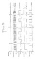
- the auxiliary signal is amplified and reshaped (signal S1 in Figure 3).
- the width of the passband of the circuit 12 is chosen as a function of the bandwidth occupied by the modulation and possible variations in the reading speed (at most about 5% on either side of the nominal speed).
- a demodulator circuit 13 is connected to the output of circuit 12 in order, on the one hand, to supply a decoding logic circuit 14 with a demodulated digital signal (S2 in FIG. 3) and, on the other hand, to control a generator 15 of bit synchronization signal (primary synchronization signal SP in FIG. 3).
- a phase loop centered on Fo comprising a voltage-controlled oscillator 13a, a phase comparator 13b receiving the signal S1 and the output signal of the oscillator 13a, and an integrating amplifier 13c receiving the error signal provided by the comparator 13b and controlling the oscillator 13a.
- the signal S2 is taken from the output of the amplifier 13c, each change of sign of this output corresponding to a passage of the frequency Or vice versa.
- the signal at the output of the oscillator 13a indicates the attachment of the demodulator 13. This attachment signal triggers the operation of the generator 15; then the signal S2 is then preponderant for the synchronization of bits.
- the latching signal is transformed into a continuous signal SA (FIG. 3) or authorization signal which returns to zero a determined time after the last pulse emitted by the oscillator 13a, by means of a re-triggerable monostable circuit 100 .
- the logic circuit 14 includes a format recognition circuit 16 loaded by the decoded bits of the signal S2 at the rate of the signal SP.
- a format recognition circuit 16 loaded by the decoded bits of the signal S2 at the rate of the signal SP.
- the content of register 17 is compared with the content of a register 18 by means of a comparator 19 which, in the event of a tie, increments a counter 20 by one unit and, in the event of an inequality, controls the transfer in the register 18 of the contents of register 17.
- the content of the register 18, that is to say the auxiliary information associated with the recording being listened to is transferred to a register 22 d an interface circuit 21.
- the interface circuit 21 also contains registers 23, where other information is stored, for example relating to the time and place where the reproduction in progress takes place.
- the detection circuit 11 is ready for the detection and the transfer of new auxiliary information, or possibly of the same if the same recording is replayed.
- the auxiliary signal is repeated all along the track or tracks where the main sound information is recorded, the signal SA is advantageously used as the closing control signal of a switch 1 connected to the input of the preamplifier P.
- the signal SA is advantageously used as the closing control signal of a switch 1 connected to the input of the preamplifier P.
Landscapes
- Engineering & Computer Science (AREA)
- Computer Security & Cryptography (AREA)
- Signal Processing (AREA)
- Multimedia (AREA)
- Signal Processing For Digital Recording And Reproducing (AREA)
- Recording Or Reproducing By Magnetic Means (AREA)
- Signal Processing Not Specific To The Method Of Recording And Reproducing (AREA)
- Indexing, Searching, Synchronizing, And The Amount Of Synchronization Travel Of Record Carriers (AREA)
- Management Or Editing Of Information On Record Carriers (AREA)
Claims (9)
Priority Applications (1)
| Application Number | Priority Date | Filing Date | Title |
|---|---|---|---|
| AT80400872T ATE6104T1 (de) | 1979-06-18 | 1980-06-16 | Verfahren zur kontrolle des ablesens einer tonaufnahme bei zuhilfenahme eines zu dieser aufnahme zusaetzlichen signals. |
Applications Claiming Priority (2)
| Application Number | Priority Date | Filing Date | Title |
|---|---|---|---|
| FR7915535A FR2459532B1 (fr) | 1979-06-18 | 1979-06-18 | Procede pour associer une information auxiliaire a une information principale enregistree et application au controle de la reproduction d'information enregistree |
| FR7915535 | 1979-06-18 |
Publications (2)
| Publication Number | Publication Date |
|---|---|
| EP0021971A1 EP0021971A1 (de) | 1981-01-07 |
| EP0021971B1 true EP0021971B1 (de) | 1984-02-01 |
Family
ID=9226730
Family Applications (1)
| Application Number | Title | Priority Date | Filing Date |
|---|---|---|---|
| EP80400872A Expired EP0021971B1 (de) | 1979-06-18 | 1980-06-16 | Verfahren zur Kontrolle des Ablesens einer Tonaufnahme bei Zuhilfenahme eines zu dieser Aufnahme zusätzlichen Signals |
Country Status (5)
| Country | Link |
|---|---|
| US (1) | US4333113A (de) |
| EP (1) | EP0021971B1 (de) |
| AT (1) | ATE6104T1 (de) |
| DE (1) | DE3066375D1 (de) |
| FR (1) | FR2459532B1 (de) |
Cited By (1)
| Publication number | Priority date | Publication date | Assignee | Title |
|---|---|---|---|---|
| DE3726367A1 (de) * | 1986-08-08 | 1988-02-18 | Dictaphone Corp | Markierungssignale und markierungsdatenbloecke fuer den einsatz mit aufgenommenen mitteilungen |
Families Citing this family (33)
| Publication number | Priority date | Publication date | Assignee | Title |
|---|---|---|---|---|
| NZ199275A (en) * | 1980-12-16 | 1984-11-09 | Minnesota Mining Mfg Australia | Verification of recorded messages |
| FR2515403A1 (fr) * | 1981-10-28 | 1983-04-29 | Quadrivium Inf | Procede d'identification d'un enregistrement sonore et installation de duplication mettant en oeuvre le procede |
| JPS58133689A (ja) * | 1982-02-02 | 1983-08-09 | Sony Corp | デイジタルオ−デイオデイスク装置 |
| FR2534433B1 (fr) * | 1982-10-08 | 1986-04-11 | Thomson Csf | Procede de protection d'une sequence d'images video contre une utilisation frauduleuse et dispositifs pour la mise en oeuvre de ce procede |
| US4636879A (en) * | 1983-07-06 | 1987-01-13 | Ricoh Company, Ltd. | VTR system |
| US4823210A (en) * | 1984-08-13 | 1989-04-18 | Verbatim Corporation | Copy protected disk |
| JPH0772924B2 (ja) * | 1985-06-13 | 1995-08-02 | ソニー株式会社 | 記録方法、記録再生方法、記録装置及び記録再生装置 |
| JPH0743825B2 (ja) * | 1985-12-04 | 1995-05-15 | ソニー株式会社 | ダビング方式 |
| CA1324436C (en) * | 1986-08-08 | 1993-11-16 | John J. Dwyer | Display for modular dictation/transcription system |
| US4847710A (en) * | 1986-11-26 | 1989-07-11 | Citec Corporation | Multitrack recording apparatus which stops the recording medium on the basis of recorded musical timing data |
| GB2199689A (en) * | 1987-01-05 | 1988-07-13 | Thomas Claude Henry Keen | Recording of an information signal |
| US5172111A (en) * | 1987-08-31 | 1992-12-15 | Olivo Jr John W | Stored media screening device |
| GB8724569D0 (en) * | 1987-10-20 | 1987-11-25 | Arbiter Ltd John & Ivor | Programmable audio-visual reproduction apparatus |
| NL8900934A (nl) * | 1989-04-14 | 1990-11-01 | Philips Nv | Inrichting voor het opnemen van een audiosignaal. |
| US5231542A (en) * | 1991-01-23 | 1993-07-27 | Heindel Alvin D | Method and device for improving bass response in magnetic tape recording |
| US6611607B1 (en) | 1993-11-18 | 2003-08-26 | Digimarc Corporation | Integrating digital watermarks in multimedia content |
| US7313251B2 (en) | 1993-11-18 | 2007-12-25 | Digimarc Corporation | Method and system for managing and controlling electronic media |
| US6944298B1 (en) | 1993-11-18 | 2005-09-13 | Digimare Corporation | Steganographic encoding and decoding of auxiliary codes in media signals |
| US5768426A (en) | 1993-11-18 | 1998-06-16 | Digimarc Corporation | Graphics processing system employing embedded code signals |
| US5748763A (en) | 1993-11-18 | 1998-05-05 | Digimarc Corporation | Image steganography system featuring perceptually adaptive and globally scalable signal embedding |
| US6614914B1 (en) | 1995-05-08 | 2003-09-02 | Digimarc Corporation | Watermark embedder and reader |
| US6983051B1 (en) | 1993-11-18 | 2006-01-03 | Digimarc Corporation | Methods for audio watermarking and decoding |
| TW320811B (de) * | 1996-04-12 | 1997-11-21 | Sony Co Ltd | |
| US6011765A (en) * | 1996-04-12 | 2000-01-04 | Sony Corporation | Recording medium having copying protection signals recorded in superposition on main signals |
| US20030056103A1 (en) * | 2000-12-18 | 2003-03-20 | Levy Kenneth L. | Audio/video commerce application architectural framework |
| US6381341B1 (en) * | 1996-05-16 | 2002-04-30 | Digimarc Corporation | Watermark encoding method exploiting biases inherent in original signal |
| US7305104B2 (en) | 2000-04-21 | 2007-12-04 | Digimarc Corporation | Authentication of identification documents using digital watermarks |
| US6674876B1 (en) * | 2000-09-14 | 2004-01-06 | Digimarc Corporation | Watermarking in the time-frequency domain |
| EP1344212B1 (de) | 2000-12-14 | 2008-08-13 | ECD Systems, Inc. | Verfahren zur Authentifizierung eines optischen Aufzeichnungsmediums und ein optisches Aufzeichnungsmedium |
| US8055899B2 (en) * | 2000-12-18 | 2011-11-08 | Digimarc Corporation | Systems and methods using digital watermarking and identifier extraction to provide promotional opportunities |
| US7562396B2 (en) * | 2001-08-21 | 2009-07-14 | Ecd Systems, Inc. | Systems and methods for media authentication |
| US7643393B2 (en) * | 2001-12-12 | 2010-01-05 | Ecd Systems, Inc. | Systems and methods for optical media modification |
| US7716485B2 (en) * | 2002-02-01 | 2010-05-11 | Sca Ipla Holdings Inc. | Systems and methods for media authentication |
Family Cites Families (12)
| Publication number | Priority date | Publication date | Assignee | Title |
|---|---|---|---|---|
| US2807797A (en) * | 1955-03-14 | 1957-09-24 | California Research Corp | Noise elimination in fm recording |
| US3171902A (en) * | 1959-05-27 | 1965-03-02 | Dictaphone Corp | Apparatus and method for controlling remotely-operated dictation equipment |
| NL278652A (de) * | 1961-05-29 | |||
| US3573393A (en) * | 1967-06-26 | 1971-04-06 | Newell Ind | Tape handling control element and system for reversal of tape movement during low sound levels |
| US3591731A (en) * | 1968-09-23 | 1971-07-06 | Leigh Prod Inc | Method and apparatus for recording real time superimposed on other information |
| CA1067997A (en) * | 1974-07-15 | 1979-12-11 | Jacob De Boer | Servo system for controlling the position of a reading head |
| DE2448445A1 (de) * | 1974-10-10 | 1976-04-22 | Budapesti Radiotechnikai Gyar | Vorrichtung zur magnetischen signalaufzeichnung |
| US4086634A (en) * | 1975-07-30 | 1978-04-25 | Cook Laboratories, Inc. | Method and apparatus for preparing recorded program material to prevent unauthorized duplication by magnetic tape recording |
| NL7600470A (nl) * | 1976-01-17 | 1977-07-19 | Philips Nv | Servosysteem voor het sturen van de positie van een magneetkop ten opzichte van een te volgen spoor. |
| NL7702815A (nl) * | 1977-03-16 | 1978-09-19 | Philips Nv | Werkwijze voor het regelen van de positie van een schrijf- respektievelijk leeskop en een inrichting voor het uitvoeren van de werkwijze. |
| US4121263A (en) * | 1977-07-27 | 1978-10-17 | The Singer Company | Method and apparatus for control signal separation to regain synchronization between a visual image projector and an audio program |
| US4188646A (en) * | 1978-05-30 | 1980-02-12 | Sperry Rand Corporation | Sectorized data path following servo system |
-
1979
- 1979-06-18 FR FR7915535A patent/FR2459532B1/fr not_active Expired
-
1980
- 1980-06-16 US US06/160,007 patent/US4333113A/en not_active Expired - Lifetime
- 1980-06-16 DE DE8080400872T patent/DE3066375D1/de not_active Expired
- 1980-06-16 AT AT80400872T patent/ATE6104T1/de not_active IP Right Cessation
- 1980-06-16 EP EP80400872A patent/EP0021971B1/de not_active Expired
Cited By (1)
| Publication number | Priority date | Publication date | Assignee | Title |
|---|---|---|---|---|
| DE3726367A1 (de) * | 1986-08-08 | 1988-02-18 | Dictaphone Corp | Markierungssignale und markierungsdatenbloecke fuer den einsatz mit aufgenommenen mitteilungen |
Also Published As
| Publication number | Publication date |
|---|---|
| ATE6104T1 (de) | 1984-02-15 |
| DE3066375D1 (en) | 1984-03-08 |
| FR2459532A1 (fr) | 1981-01-09 |
| FR2459532B1 (fr) | 1987-07-31 |
| US4333113A (en) | 1982-06-01 |
| EP0021971A1 (de) | 1981-01-07 |
Similar Documents
| Publication | Publication Date | Title |
|---|---|---|
| EP0021971B1 (de) | Verfahren zur Kontrolle des Ablesens einer Tonaufnahme bei Zuhilfenahme eines zu dieser Aufnahme zusätzlichen Signals | |
| EP0078218B1 (de) | Identifizierungsverfahren für unerlaubte Schallaufzeichnungen und Kopiergerät zur Durchführung des Verfahrens | |
| FR2681997A1 (fr) | Procede et dispositif d'identification automatique d'un programme comportant un signal sonore. | |
| EP0162071A1 (de) | Verfahren und anordnung gegen unerlaubtes kopieren von kinematographischen und videobildträgern | |
| FR2471107A1 (fr) | Appareil de reproduction d'un disque d'enregistrement d'un signal a modulation d'impulsions codees | |
| CA2055498C (fr) | Recepteur-enregistreur d'emissions de television | |
| FR2513420A1 (fr) | Lecteur de disque notamment de disque numerique optique | |
| FR2559002A1 (fr) | Procede et dispositif de detection d'une information audiovisuelle diffusee par un emetteur | |
| BE1003591A3 (fr) | Procede de memorisation automatique de references d'enregistrements portes par un support. | |
| EP0138699B1 (de) | Magnetbandaufzeichnungsgerät zur Wiedergabe eines Zeit-Kodes unabhängig von der Laufgeschwindigkeit des Magnetbandes | |
| FR2600806A1 (fr) | Procede et appareil de detection de signal de commande | |
| EP0473677B1 (de) | Vorrichtung zur kinofilm-tonwiedergabe in hifi-qualität | |
| FR2527819A1 (fr) | Procede d'enregistrement et de lecture par echantillonnage de signaux sonores sur un support magnetique | |
| WO1984003166A1 (fr) | Dispositif de protection de bandes magnetiques, ou autres supports d'enregistrement, ou d'emissions de television ou de radio contre la lecture et/ou la reproduction non autorisees | |
| FR2570538A1 (fr) | Dispositif lecteur de support d'information, notamment cassettes sonores | |
| EP0632922B1 (de) | VORRICHTUNG ZUR WIEDERGABE VON FILMTON IN HiFi-QUALITÄT | |
| FR2636764A1 (fr) | Systeme d'enregistrement rapide de sequences sonores et/ou visuelles | |
| FR2607308A1 (fr) | Procede et dispositif de signalisation de sequence sur un support d'enregistrement et application a la programmation cyclique sequentielle alternee de plusieurs appareils de reproduction a partir de ladite signalisation | |
| FR2832831A1 (fr) | Dispositif d'asservissement de systemes multimedias numeriques | |
| BE1007720A6 (fr) | Procede et dispositif controlant la reproduction d'informations portees par au moins deux supports en cas de lecture successive. | |
| FR2661031A1 (fr) | Appareil de determination du type de piste pour la reproduction d'un disque magnetique. | |
| EP0478443A1 (de) | Vorrichtung für Spiel und Sprachenunterricht | |
| FR2649567A1 (fr) | Appareil video a image fixe | |
| FR2654886A1 (fr) | Procede de multiplexage d'un signal de sequences sonores dans un signal d'image video destine a etre enregistre sur un videodisque et systeme de restitution associe. | |
| FR2627002A1 (fr) | Procede pour lire de facon aleatoire une succession d'informations disposees sur un support materiel et dispositif pour sa mise en oeuvre |
Legal Events
| Date | Code | Title | Description |
|---|---|---|---|
| PUAI | Public reference made under article 153(3) epc to a published international application that has entered the european phase |
Free format text: ORIGINAL CODE: 0009012 |
|
| AK | Designated contracting states |
Designated state(s): AT BE CH DE GB IT LI LU NL SE |
|
| 17P | Request for examination filed |
Effective date: 19810707 |
|
| ITF | It: translation for a ep patent filed | ||
| GRAA | (expected) grant |
Free format text: ORIGINAL CODE: 0009210 |
|
| RAP1 | Party data changed (applicant data changed or rights of an application transferred) |
Owner name: SOCIETE SCOME FRANCE |
|
| AK | Designated contracting states |
Designated state(s): AT BE CH DE GB IT LI LU NL SE |
|
| REF | Corresponds to: |
Ref document number: 6104 Country of ref document: AT Date of ref document: 19840215 Kind code of ref document: T |
|
| REF | Corresponds to: |
Ref document number: 3066375 Country of ref document: DE Date of ref document: 19840308 |
|
| PLBE | No opposition filed within time limit |
Free format text: ORIGINAL CODE: 0009261 |
|
| STAA | Information on the status of an ep patent application or granted ep patent |
Free format text: STATUS: NO OPPOSITION FILED WITHIN TIME LIMIT |
|
| 26N | No opposition filed | ||
| PGFP | Annual fee paid to national office [announced via postgrant information from national office to epo] |
Ref country code: AT Payment date: 19910528 Year of fee payment: 12 |
|
| PGFP | Annual fee paid to national office [announced via postgrant information from national office to epo] |
Ref country code: CH Payment date: 19910610 Year of fee payment: 12 |
|
| PGFP | Annual fee paid to national office [announced via postgrant information from national office to epo] |
Ref country code: GB Payment date: 19910611 Year of fee payment: 12 |
|
| PGFP | Annual fee paid to national office [announced via postgrant information from national office to epo] |
Ref country code: SE Payment date: 19910619 Year of fee payment: 12 |
|
| PGFP | Annual fee paid to national office [announced via postgrant information from national office to epo] |
Ref country code: LU Payment date: 19910621 Year of fee payment: 12 |
|
| ITTA | It: last paid annual fee | ||
| PGFP | Annual fee paid to national office [announced via postgrant information from national office to epo] |
Ref country code: NL Payment date: 19910630 Year of fee payment: 12 |
|
| PGFP | Annual fee paid to national office [announced via postgrant information from national office to epo] |
Ref country code: BE Payment date: 19910715 Year of fee payment: 12 |
|
| EPTA | Lu: last paid annual fee | ||
| PG25 | Lapsed in a contracting state [announced via postgrant information from national office to epo] |
Ref country code: LU Free format text: LAPSE BECAUSE OF NON-PAYMENT OF DUE FEES Effective date: 19920616 Ref country code: GB Effective date: 19920616 Ref country code: AT Effective date: 19920616 |
|
| PG25 | Lapsed in a contracting state [announced via postgrant information from national office to epo] |
Ref country code: SE Effective date: 19920617 |
|
| PG25 | Lapsed in a contracting state [announced via postgrant information from national office to epo] |
Ref country code: LI Effective date: 19920630 Ref country code: CH Effective date: 19920630 Ref country code: BE Effective date: 19920630 |
|
| PGFP | Annual fee paid to national office [announced via postgrant information from national office to epo] |
Ref country code: DE Payment date: 19921217 Year of fee payment: 13 |
|
| BERE | Be: lapsed |
Owner name: SOC. SCOME FRANCE Effective date: 19920630 |
|
| PG25 | Lapsed in a contracting state [announced via postgrant information from national office to epo] |
Ref country code: NL Effective date: 19930101 |
|
| GBPC | Gb: european patent ceased through non-payment of renewal fee |
Effective date: 19920616 |
|
| NLV4 | Nl: lapsed or anulled due to non-payment of the annual fee | ||
| REG | Reference to a national code |
Ref country code: CH Ref legal event code: PL |
|
| PG25 | Lapsed in a contracting state [announced via postgrant information from national office to epo] |
Ref country code: DE Effective date: 19940301 |
|
| EUG | Se: european patent has lapsed |
Ref document number: 80400872.0 Effective date: 19930109 |