EP0473677B1 - Vorrichtung zur kinofilm-tonwiedergabe in hifi-qualität - Google Patents
Vorrichtung zur kinofilm-tonwiedergabe in hifi-qualität Download PDFInfo
- Publication number
- EP0473677B1 EP0473677B1 EP90908552A EP90908552A EP0473677B1 EP 0473677 B1 EP0473677 B1 EP 0473677B1 EP 90908552 A EP90908552 A EP 90908552A EP 90908552 A EP90908552 A EP 90908552A EP 0473677 B1 EP0473677 B1 EP 0473677B1
- Authority
- EP
- European Patent Office
- Prior art keywords
- sound
- memory
- reading
- film
- track
- Prior art date
- Legal status (The legal status is an assumption and is not a legal conclusion. Google has not performed a legal analysis and makes no representation as to the accuracy of the status listed.)
- Expired - Lifetime
Links
- 230000003287 optical effect Effects 0.000 claims description 8
- 230000006870 function Effects 0.000 claims description 6
- 230000003111 delayed effect Effects 0.000 claims 1
- 230000001360 synchronised effect Effects 0.000 abstract description 4
- 230000008439 repair process Effects 0.000 abstract description 3
- 230000005540 biological transmission Effects 0.000 abstract 1
- 230000000694 effects Effects 0.000 description 11
- 238000003860 storage Methods 0.000 description 5
- 230000006872 improvement Effects 0.000 description 4
- 238000009792 diffusion process Methods 0.000 description 3
- 238000009826 distribution Methods 0.000 description 3
- 238000005516 engineering process Methods 0.000 description 3
- 238000011144 upstream manufacturing Methods 0.000 description 3
- 230000001934 delay Effects 0.000 description 2
- 230000008034 disappearance Effects 0.000 description 2
- 230000009191 jumping Effects 0.000 description 2
- 238000000034 method Methods 0.000 description 2
- 230000004048 modification Effects 0.000 description 2
- 238000012986 modification Methods 0.000 description 2
- 230000001133 acceleration Effects 0.000 description 1
- 238000004026 adhesive bonding Methods 0.000 description 1
- 230000008901 benefit Effects 0.000 description 1
- 230000008859 change Effects 0.000 description 1
- 238000012822 chemical development Methods 0.000 description 1
- 238000001311 chemical methods and process Methods 0.000 description 1
- 230000036461 convulsion Effects 0.000 description 1
- 230000001186 cumulative effect Effects 0.000 description 1
- 238000005520 cutting process Methods 0.000 description 1
- 230000007547 defect Effects 0.000 description 1
- 230000002950 deficient Effects 0.000 description 1
- 238000001514 detection method Methods 0.000 description 1
- 238000005286 illumination Methods 0.000 description 1
- 238000012423 maintenance Methods 0.000 description 1
- 238000004519 manufacturing process Methods 0.000 description 1
- 230000003071 parasitic effect Effects 0.000 description 1
- 230000008569 process Effects 0.000 description 1
- 238000005204 segregation Methods 0.000 description 1
- 238000004088 simulation Methods 0.000 description 1
Images

Classifications
-
- G—PHYSICS
- G03—PHOTOGRAPHY; CINEMATOGRAPHY; ANALOGOUS TECHNIQUES USING WAVES OTHER THAN OPTICAL WAVES; ELECTROGRAPHY; HOLOGRAPHY
- G03B—APPARATUS OR ARRANGEMENTS FOR TAKING PHOTOGRAPHS OR FOR PROJECTING OR VIEWING THEM; APPARATUS OR ARRANGEMENTS EMPLOYING ANALOGOUS TECHNIQUES USING WAVES OTHER THAN OPTICAL WAVES; ACCESSORIES THEREFOR
- G03B31/00—Associated working of cameras or projectors with sound-recording or sound-reproducing means
- G03B31/04—Associated working of cameras or projectors with sound-recording or sound-reproducing means in which sound track is not on, but is synchronised with, a moving-picture film
-
- G—PHYSICS
- G11—INFORMATION STORAGE
- G11B—INFORMATION STORAGE BASED ON RELATIVE MOVEMENT BETWEEN RECORD CARRIER AND TRANSDUCER
- G11B27/00—Editing; Indexing; Addressing; Timing or synchronising; Monitoring; Measuring tape travel
- G11B27/10—Indexing; Addressing; Timing or synchronising; Measuring tape travel
-
- G—PHYSICS
- G11—INFORMATION STORAGE
- G11B—INFORMATION STORAGE BASED ON RELATIVE MOVEMENT BETWEEN RECORD CARRIER AND TRANSDUCER
- G11B27/00—Editing; Indexing; Addressing; Timing or synchronising; Monitoring; Measuring tape travel
- G11B27/10—Indexing; Addressing; Timing or synchronising; Measuring tape travel
- G11B27/19—Indexing; Addressing; Timing or synchronising; Measuring tape travel by using information detectable on the record carrier
- G11B27/28—Indexing; Addressing; Timing or synchronising; Measuring tape travel by using information detectable on the record carrier by using information signals recorded by the same method as the main recording
-
- G—PHYSICS
- G11—INFORMATION STORAGE
- G11B—INFORMATION STORAGE BASED ON RELATIVE MOVEMENT BETWEEN RECORD CARRIER AND TRANSDUCER
- G11B27/00—Editing; Indexing; Addressing; Timing or synchronising; Monitoring; Measuring tape travel
- G11B27/10—Indexing; Addressing; Timing or synchronising; Measuring tape travel
- G11B27/19—Indexing; Addressing; Timing or synchronising; Measuring tape travel by using information detectable on the record carrier
- G11B27/28—Indexing; Addressing; Timing or synchronising; Measuring tape travel by using information detectable on the record carrier by using information signals recorded by the same method as the main recording
- G11B27/32—Indexing; Addressing; Timing or synchronising; Measuring tape travel by using information detectable on the record carrier by using information signals recorded by the same method as the main recording on separate auxiliary tracks of the same or an auxiliary record carrier
- G11B27/321—Indexing; Addressing; Timing or synchronising; Measuring tape travel by using information detectable on the record carrier by using information signals recorded by the same method as the main recording on separate auxiliary tracks of the same or an auxiliary record carrier used signal consists of two 180-degr. phase shifted signals of the same frequency
-
- G—PHYSICS
- G11—INFORMATION STORAGE
- G11B—INFORMATION STORAGE BASED ON RELATIVE MOVEMENT BETWEEN RECORD CARRIER AND TRANSDUCER
- G11B27/00—Editing; Indexing; Addressing; Timing or synchronising; Monitoring; Measuring tape travel
- G11B27/10—Indexing; Addressing; Timing or synchronising; Measuring tape travel
- G11B27/19—Indexing; Addressing; Timing or synchronising; Measuring tape travel by using information detectable on the record carrier
- G11B27/28—Indexing; Addressing; Timing or synchronising; Measuring tape travel by using information detectable on the record carrier by using information signals recorded by the same method as the main recording
- G11B27/32—Indexing; Addressing; Timing or synchronising; Measuring tape travel by using information detectable on the record carrier by using information signals recorded by the same method as the main recording on separate auxiliary tracks of the same or an auxiliary record carrier
- G11B27/322—Indexing; Addressing; Timing or synchronising; Measuring tape travel by using information detectable on the record carrier by using information signals recorded by the same method as the main recording on separate auxiliary tracks of the same or an auxiliary record carrier used signal is digitally coded
- G11B27/323—Time code signal, e.g. on a cue track as SMPTE- or EBU-time code
-
- G—PHYSICS
- G11—INFORMATION STORAGE
- G11B—INFORMATION STORAGE BASED ON RELATIVE MOVEMENT BETWEEN RECORD CARRIER AND TRANSDUCER
- G11B7/00—Recording or reproducing by optical means, e.g. recording using a thermal beam of optical radiation by modifying optical properties or the physical structure, reproducing using an optical beam at lower power by sensing optical properties; Record carriers therefor
- G11B7/002—Recording, reproducing or erasing systems characterised by the shape or form of the carrier
- G11B7/003—Recording, reproducing or erasing systems characterised by the shape or form of the carrier with webs, filaments or wires, e.g. belts, spooled tapes or films of quasi-infinite extent
- G11B7/0032—Recording, reproducing or erasing systems characterised by the shape or form of the carrier with webs, filaments or wires, e.g. belts, spooled tapes or films of quasi-infinite extent for moving-picture soundtracks, i.e. cinema
-
- G—PHYSICS
- G11—INFORMATION STORAGE
- G11B—INFORMATION STORAGE BASED ON RELATIVE MOVEMENT BETWEEN RECORD CARRIER AND TRANSDUCER
- G11B2220/00—Record carriers by type
- G11B2220/20—Disc-shaped record carriers
- G11B2220/25—Disc-shaped record carriers characterised in that the disc is based on a specific recording technology
- G11B2220/2537—Optical discs
- G11B2220/2545—CDs
-
- G—PHYSICS
- G11—INFORMATION STORAGE
- G11B—INFORMATION STORAGE BASED ON RELATIVE MOVEMENT BETWEEN RECORD CARRIER AND TRANSDUCER
- G11B27/00—Editing; Indexing; Addressing; Timing or synchronising; Monitoring; Measuring tape travel
- G11B27/002—Programmed access in sequence to a plurality of record carriers or indexed parts, e.g. tracks, thereof, e.g. for editing
-
- G—PHYSICS
- G11—INFORMATION STORAGE
- G11B—INFORMATION STORAGE BASED ON RELATIVE MOVEMENT BETWEEN RECORD CARRIER AND TRANSDUCER
- G11B27/00—Editing; Indexing; Addressing; Timing or synchronising; Monitoring; Measuring tape travel
- G11B27/02—Editing, e.g. varying the order of information signals recorded on, or reproduced from, record carriers
- G11B27/06—Cutting and rejoining; Notching, or perforating record carriers otherwise than by recording styli
Definitions
- the present invention relates to a high fidelity sound reproduction device for the cinema. Its purpose is to increase the quality of the sound that accompanies the projection of the images of films that we are watching.
- cinema films include a soundtrack and an imagetrack.
- the soundtrack is laterally offset on the film with respect to the image strip.
- the image strip goes by jerks, in front of a projector lamp and the image is projected on a screen that the spectators look at.
- the soundtrack passes in front of a sound detector linked to an acoustic chain to emit the sounds to be heard.
- the player of the soundtrack is offset with respect to the projection lamp.
- the sound player is placed upstream of the progress of the film.
- a process for transcribing sound on the sound track has been developed which borrows the same techniques.
- the sound detector in principle comprises a lamp which illuminates, by transparency or by reflection, the soundtrack facing a photodetector cell.
- the light energy captured by the photodetector cell takes into account, at at any time, the percentage of darkening of the corresponding illuminated section of the strip.
- the optical sound track has two major defects.
- the measurable dynamic is weak. Indeed it is limited to around 40 dB while a dynamic range of 90 dB would be necessary.
- the bandwidth likely to be passed on each stereophonic channel is weak. It is generally accepted that a bandwidth of 11 KHz is an acceptable result. A bandwidth of 14 KHz being obtained only by chance or at great expense: that is to say less easily reproducible under current conditions in all cinemas.
- the document WO-A-8 504 024 relates to a teaching in which it is proposed to replace the conventional sound coding by an encrypted coding. Codes are recorded next to the images, and are linked to addresses on a laser disc where a corresponding sound is stored. It is noted in particular in this document that a servo system is provided so that the sound medium is synchronized with the image medium. This means that, if there was ever a cut in the film, the laser disc would continue to emit the sound corresponding to the cut part, but that this sound should be emitted at a faster speed, so as to compensate for the effects of delays of the laser disc. on the image scrolling, effects of delays due to the clipping of the film, This is the worst effect.
- the document FR-A-2 594 238 proposes a teaching of the same type which leads, in particular when the cuts in the film are greater than four seconds, in diffusion disorders.
- Another sound medium is used, preferably of course a laser disc associated with a laser disc player. but the sound to be emitted is read in advance. Since we are not in real time, the sound played is stored in a memory. This stored sound is read from this memory, and is broadcast, at the appropriate time: in correspondence with the passing images. When a cut appears in the film, we avoid playing the prerecorded parts of the sound that correspond to the images that have been removed from the film. We jump to the following parts of the sound. In this way, problems of rise time of reading of the medium used are avoided. This is achieved because searching and reading from memory is almost instantaneous: it is much faster than searching and reading from the laser disk.
- FIG. 1 schematically shows, in a cinema projector 1, a detector 2 of an optically coded signal on a soundtrack 28 of a film 3 and a projection lamp 4 for projecting the images contained on an image strip 5 of the same movie.
- the soundtrack detector is placed upstream relative to the direction of travel of the film 3 of the lamp 4.
- the offset which results from this position upstream of the detector 2 is noted H in the schematic representation of the film 3. This means that, when the lamp 4 illuminates an image n of the image band 5, the detector 2 detects a sound N corresponding to the passing image.
- the offset H corresponds to the passage time from 18 to 20 images. It is standardized.
- This shift H is that if just after the image has been cut, the film 3 has been cut and a number "d" of images has been skipped, there will be a shift between the correspondence of the sound and the 'picture.
- This offset lasts the passage time of this height H of film in front of the lamp 4 or in front of the detector 2. Given a speed of passage of the order of 24 images per second, the duration of the resulting offset sound effect is of the order of a little more than half a second: the the fact that the sound "jumps" is really noticeable.
- This other system 6 in this preferred example comprises a laser source 8 illuminating an optical track 9 of the disc 7; the illumination signal 10 is detected by a cell 11.
- a motor 12 drives the disc 7 in rotation.
- the system of the invention also includes a memory 13 for recording sounds. This memory is managed by a management system 14 which makes it possible to read the sound in advance with respect to the passage of the corresponding images of the film. Assuming for example that at a given time the corresponding projected image of the film is image n, instead of reading the sound N on disk 7, we read at the time of the passage of the image n the sound N + Mr.
- the management system 14 causes the storage of the N + M sound in the memory 13. This sound is stored, at least temporarily, and it is taken later. If all goes well, the duration of temporary storage of the sound N + M in the memory 13 is equal to the time necessary to project M images. Thus, at the moment when an image n + m is projected, the N + M sound which had previously been stored therein is taken from memory 13.
- the sounds are digitally coded on track 9. Consequently their storage in memory words of memory 13 does not present any difficulties.
- the digitally encoded sound is subsequently transformed into an analog signal by a digital analog converter 15.
- the particularity of the invention consists just, from this point of view, in introducing the memory 13 between the output of the photodetector 11 and the input of the digital analog converter 15
- the signal delivered by the digital analog converter 15 is then sent to a device 16 for acoustic effects which is conventionally in relation with several broadcasting channels.
- the diffusion of the sound is thus executed in the same way as the diffusion of the sound could be in the state of the art.
- a routing circuit 17 capable of detecting the presence of a synchronization coding of the sound to be produced by the second playback system, makes it possible either to implement the improvement of the invention, or to 'ignore if film 3 has not been prepared for this.
- the temporary storage of sounds in memory 13 can be organized in different ways.
- the memory 13 comprises M shift registers which flow successively into each other. In this case, the sound is always stored in the first register and the sound is played from the last.
- the sounds distributed by a laser disc include a digital coding providing information not only on the frequency and amplitude characteristics of the sound to be produced, but also on the address of the corresponding part of the sound in the laser disc itself.
- a random access memory comprising a first pointer address to store in writing the successive sounds in memory boxes whose addresses are each time incremented.
- This random access memory also includes a second pointer to addresses of the memory words for picking up the sounds to be broadcast.
- the addresses of the sampled memory words are reduced by the number of memory words corresponding to the stored sounds.
- the two pointers therefore change, according to the arrows 18 and 19 respectively the addresses for writing and reading respectively in the memory 13.
- a sort of rotating memory is created, turning endlessly on itself.
- each of the address pointers starts from zero once it has reached the maximum address of the memory.
- the memory 13 is then of the first in first out type (FIFO in Anglo-Saxon literature).
- the memory 13 is an analog memory, for example a delay line.
- the "address" of the sound on the sound track can be an address corresponding to numerous memory words in the memory, all linked to the same images.
- the same tear was to have been intended to cause the sound from NH to jump to N + dH .
- This is linked only to the difference in position between the lamp 4 and the reader 2.
- this corresponding offset of the sound address can be used to control , additionally, the memory read pointer 13.
- the sound address is coded optically superimposed on the soundtrack.
- the sound address is coded, again optically, in the inter-image space of the film.
- the original soundtrack is replaced by an optical synchronization signal.
- a sound address signal 20 is sent to an address coder.
- this address coder may include a first subtractor 21 with two inputs. A first positive input receives a sound address while a second negative input receives the previous sound address. In order for the addresses to be presented together, the previous address passes through a delay line 22.
- the two addresses have a unit increment.
- This increment is sent to a first input of an adder 23 which receives, on a second input, its previous output signal. Consequently, the adder 23 now delivers an address incremented by a notch relative to the address which it previously produced. This address is used to move the pointer for reading the memory address according to arrow 19.
- the subtractor 21 has an increment d instead of a unit increment. This increment d has just been added in the adder 23 to the previous address and causes a read jump 24 of the memory 13 so that unnecessary sounds (corresponding to the disappeared part of the image) are not broadcast . By doing so it solves the timing problems of synchronization of the laser disc player.
- a second memory 25 is preferably used which receives the sound addresses and which stores them temporarily for the duration corresponding to the passage of the H images.
- the memory 25 can be of the same type as the memory 13: it can be of the first in first out type. It is only different from the latter in that there is no jump in the reading address of the memory when there is a cut in the film. Indeed, it is the information content of the memory words stored in this memory 25 which is itself representative of these jumps.
- the address of the sound read on the soundtrack is introduced on a first positive input of a comparator 27 at the same time as, on a second positive input of this comparator 27, the size M which is imposed as a memory keeper 13. This size corresponds exactly to the reading advance which it is desired to impose.
- the comparator 27 delivers a signal which is no longer zero: it is substantially equal to d (at the start).
- This signal da has the effect of accelerating the speed of rotation 12 of the system 6, within a range tolerated by this system.
- the detector cell 11 delivers faster both the contents of the memory words to be recorded in the memory 13, as well as the addresses of these memory words. Since these addresses read thus increment faster than those normally debited by the soundtrack (after the tear), the gap is reduced, and little by little the motor 12 resumes its normal speed. We thus caused by the acceleration of the recording the catching up of difference which it is necessary to maintain between the writing and the reading of the memory 13.
- Another problem to be solved consists in creating the synchronization of the starting of the laser disc with the film.
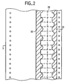
- a sound track 28 has for example two channels with optical modulation 31-32 in phase opposition known as out of phase. This global modulation is between 7 and 11KHz.
- This modulation is itself coded (in amplitude or frequency) to represent the addresses of sounds on the soundtrack. These addresses are then decoded in the routing circuit 17.
- the circuit 17 contains a high pass filter on the out-of-phase channel to extract the out-of-phase signal with a frequency greater than 7 KHz. Additional encoding 31-32 does not replace the normally encoded sound on the soundtrack.
- FIG. 1 shows three laser reading systems: systems 6, 29 and 30. The fact of using several systems may also be necessary when the duration of the projection exceeds the duration that can be recorded on a laser disc.
Landscapes
- Physics & Mathematics (AREA)
- General Physics & Mathematics (AREA)
- Optical Recording Or Reproduction (AREA)
- Indexing, Searching, Synchronizing, And The Amount Of Synchronization Travel Of Record Carriers (AREA)
Claims (10)
- Vorrichtung (1, 6, 13, 14) zur Kinofilm-Tonwiedergabe in Hifi-Qualität, bei der ein Film (3) verwendet wird, der Tonadressen aufweist, wobei der Ton selbst sich auf einem anderen Tonträger (7) befindet, bestehend aus- einem ersten optischen Detektor (2) zur Abtastung eines ersten Synchronisationssignals (20), das die genannten Tonadressen enthält und optisch auf eine Spur (28), genannt Toncodierungsspur, codiert ist, die auf einem Kinofilm (3) an eine Spur, genannt Bildspur (5), anschließt,- einem Wiedergabegerät (16) zur Erzeugung eines Tons, der dem ersten Synchronisationssignal (20), entspricht, das in Abhängigkeit von dem Durchlauf der Toncodierungsspur (28) vor dem ersten optischen Detektor (2) abgetastet wird, und- ein Abtastsystem (6, 14, 13) zur Abtastung eines zweiten codierten Signals (9), das sich auf einem anderen Tonträger (7) als auf der Toncodierungsspur (28) befindet und dem ersten Synchronisationssignal (20) entspricht,
dadurch gekennzeichnet, daß sie ferner- einen Speicher (13) zur Speicherung des abgetasteten zweiten codierten Signals (9),- ein Steuersystem (14) mit Mitteln zum Lesen des zweiten codierten Signals (9) auf dem anderen Tonträger (7) im voraus (N+M) gegenüber dem Durchlauf von Bildern (n), die diesem zweiten codierten Signal (9) entsprechen,- Mittel zur Aufzeichnung und zur Speicherung des zweiten Signals im Speicher (13),- Mittel zur Entnahme des zweiten codierten Signals (9) aus dem Speicher (13),- Mittel zur akustischen Wiedergabe (15) des Tons, der dem zweiten codierten Signal (9) entspricht, mit Verzögerung zu dem Zeitpunkt seiner Abtastung auf dem anderen Tonträger (7) und zum gleichen Zeitpunkt, zu dem die Bilder der Bildspur durchlaufen, die dem genannten zweiten codierten Signal entsprechen, und- Mittel (24) zur Vermeidung der akustischen Wiedergabe des Abschnitts dieses genannten Tons, der den Bildern entspricht, die aufgrund eines Reparaturschnitts im Film nicht mehr vorhanden sind, in Abhängigkeit von dem ersten Synchronisationssignal (20), wobei das zweite codierte Signal, das diesem Ton entspricht, nicht aus dem Speicher (13) entnommen wird,
aufweist. - Vorrichtung nach Anspruch 1,
dadurch gekennzeichnet, daß die Steuermittel Mittel (27, 28) zum Beschleunigen der Abtastung des zweiten codierten Signals auf dem anderen Tonträger in Abhängigkeit von dem nicht wiedergegebenen Abschnitt des genannten gleichen Tons umfassen. - Vorrichtung nach einem der Ansprüche 1 oder 2,
dadurch gekennzeichnet, daß das Steuersystem- einen ersten Adressenpointer (18), der eingangs die Speicherung des zweiten Signals nach Speicherwörtern des Speichers orientiert,- einen zweiten Adressenpointer (19), der die Speicherwörter des Speichers bezeichnet, aus denen das zweite Signal zu entnehmen ist,- und Mittel (25) zur Verschiebung des zweiten Adressenpointers in Abhängigkeit von dem nicht wiederzugebenden Abschnitt des genannten gleichen Tons
aufweist. - Vorrichtung nach einem der Ansprüche 1 bis 3,
dadurch gekennzeichnet, daß es Mittel zur Abtastung einer zeitweiligen Codierung (31-32) der Tonspur aufweist, wobei diese Codierung den wiederzugebenden Ton darstellt. - Vorrichtung nach einem der Ansprüche 3 oder 4,
dadurch gekennzeichnet, daß die Pointer Zähler aufweisen und daß der zweite Pointer einen Versatzspeicher (25) aufweist, bei dem der Inhalt der Kästchen je nachdem mit Adressen geladen wird, die der zeitweiligen Codierung der Tonspur entsprechen, und bei dem das Abtasten zeitlich um eine Dauer verschoben wird (25), die gleich der Zeitdauer ist, die zwischen dem Durchlauf eines Filmabschnitts vor dem ersten Detektor einerseits und vor einer Filmprojektionslampe (4) andererseits vergeht. - Vorrichtung nach einem der Ansprüche 1 bis 5,
dadurch gekennzeichnet, daß das andere Abtastsystem ein CD-Abtastsystem mit einem Digital-Analog-Codierer (15) für das abgetastete Signal ist. - Vorrichtung nach einem der Ansprüche 1 bis 6,
dadurch gekennzeichnet, daß der Speicher (13) eine Kapazität (M) besitzt, die größer oder gleich groß ist wie die des Tons, der aufgrund eines Reparaturschnitts im Film weggelassen wird (d). - Vorrichtung nach einem der Ansprüche 1 bis 7,
dadurch gekennzeichnet, daß die Mittel zum Abtasten der Codierung Hochpaß-Filtermittel aufweisen, die mit einem Demodulator verbunden sind, dessen Bandmittenfrequenz höher ist als die Grenzfrequenz des Hochpaßfilters. - Verwendung der Vorrichtung nach einem der Ansprüche 1 bis 8 in einem Saal zur Tonwiedergabe in Hifi-Qualität.
- Verwendung einer Wiedergabe-CD als der genannte andere Tonträger (7) der Vorrichtung nach einem der Ansprüche 6 bis 8.
Applications Claiming Priority (3)
| Application Number | Priority Date | Filing Date | Title |
|---|---|---|---|
| FR8906807 | 1989-05-24 | ||
| FR8906807A FR2647561B1 (fr) | 1989-05-24 | 1989-05-24 | Dispositif haute fidelite de reproduction du son pour le cinema |
| PCT/FR1990/000366 WO1990014614A1 (fr) | 1989-05-24 | 1990-05-25 | Dispositif haute fidelite de reproduction du son pour le cinema |
Publications (2)
| Publication Number | Publication Date |
|---|---|
| EP0473677A1 EP0473677A1 (de) | 1992-03-11 |
| EP0473677B1 true EP0473677B1 (de) | 1995-08-16 |
Family
ID=9381973
Family Applications (1)
| Application Number | Title | Priority Date | Filing Date |
|---|---|---|---|
| EP90908552A Expired - Lifetime EP0473677B1 (de) | 1989-05-24 | 1990-05-25 | Vorrichtung zur kinofilm-tonwiedergabe in hifi-qualität |
Country Status (6)
| Country | Link |
|---|---|
| EP (1) | EP0473677B1 (de) |
| JP (1) | JP3245416B2 (de) |
| AU (1) | AU5743490A (de) |
| DE (1) | DE69021727T2 (de) |
| FR (1) | FR2647561B1 (de) |
| WO (1) | WO1990014614A1 (de) |
Families Citing this family (8)
| Publication number | Priority date | Publication date | Assignee | Title |
|---|---|---|---|---|
| US5450146A (en) * | 1989-05-24 | 1995-09-12 | Digital Theater Systems, L.P. | High fidelity reproduction device for cinema sound |
| JP2708961B2 (ja) * | 1990-09-28 | 1998-02-04 | デジタル・シアター・システムズ・リミテッド・パートナーシップ | 映画フイルムのデジタル位置識別子提供方法及び映画オーディオ信号生成方法 |
| US5751398A (en) * | 1990-09-28 | 1998-05-12 | Digital Theater System, Inc. | Motion picture digital sound system and method |
| US5386255A (en) * | 1990-09-28 | 1995-01-31 | Digital Theater Systems, L.P. | Motion picture digital sound system and method with primary sound storage edit capability |
| US5155510A (en) * | 1990-11-29 | 1992-10-13 | Digital Theater Systems Corporation | Digital sound system for motion pictures with analog sound track emulation |
| FR2684463A1 (fr) * | 1991-12-03 | 1993-06-04 | Lochen Elisabeth | Dispositif haute fidelite de reproduction du son au cinema. |
| FR2686986B1 (fr) * | 1992-01-31 | 1995-02-17 | Bernard Legargeant | Procede pour la projection sur un ecran de projection d'images de sequences d'images principales et accessoires, notamment d'images d'un film et des sous-titres, et systeme pour la mise en óoeuvre de ce procede. |
| AU3951293A (en) * | 1993-04-02 | 1994-03-29 | Henricus Bernardus Maria Raben | Reproduction technique for sounds, pictures or both |
Family Cites Families (5)
| Publication number | Priority date | Publication date | Assignee | Title |
|---|---|---|---|---|
| FR2410296A1 (fr) * | 1977-11-28 | 1979-06-22 | Sueur Alain | Procede d'enregistrement et de lecture de son sur film cinematographique sans decalage son et image ainsi que dispositifs et appareils utilisant ledit procede |
| AT362232B (de) * | 1980-02-19 | 1981-04-27 | Benesch Fred Ing | Einrichtung zur wiedergabe der nachtraeglichen synchronen uebersetzung der sprache von film- kopien mit lichtton |
| US4506348A (en) * | 1982-06-14 | 1985-03-19 | Allied Corporation | Variable digital delay circuit |
| NL8400619A (nl) * | 1984-02-28 | 1985-09-16 | Alfred Struik | Beeld-geluidstelsel. |
| FR2594238A1 (fr) * | 1986-02-13 | 1987-08-14 | Vallon Roger | La sonorisation des films cinematographiques par compact-disc |
-
1989
- 1989-05-24 FR FR8906807A patent/FR2647561B1/fr not_active Expired - Lifetime
-
1990
- 1990-05-25 DE DE69021727T patent/DE69021727T2/de not_active Expired - Lifetime
- 1990-05-25 WO PCT/FR1990/000366 patent/WO1990014614A1/fr not_active Ceased
- 1990-05-25 JP JP50839890A patent/JP3245416B2/ja not_active Expired - Fee Related
- 1990-05-25 EP EP90908552A patent/EP0473677B1/de not_active Expired - Lifetime
- 1990-05-25 AU AU57434/90A patent/AU5743490A/en not_active Abandoned
Non-Patent Citations (1)
| Title |
|---|
| EP-A 0 372 155 (Article 54(3) et (4) CBE) * |
Also Published As
| Publication number | Publication date |
|---|---|
| JP3245416B2 (ja) | 2002-01-15 |
| DE69021727D1 (de) | 1995-09-21 |
| JPH04507322A (ja) | 1992-12-17 |
| EP0473677A1 (de) | 1992-03-11 |
| AU5743490A (en) | 1990-12-18 |
| FR2647561A1 (fr) | 1990-11-30 |
| WO1990014614A1 (fr) | 1990-11-29 |
| FR2647561B1 (fr) | 1992-01-24 |
| DE69021727T2 (de) | 1996-02-01 |
Similar Documents
| Publication | Publication Date | Title |
|---|---|---|
| US5450146A (en) | High fidelity reproduction device for cinema sound | |
| EP0021971B1 (de) | Verfahren zur Kontrolle des Ablesens einer Tonaufnahme bei Zuhilfenahme eines zu dieser Aufnahme zusätzlichen Signals | |
| EP0078218B1 (de) | Identifizierungsverfahren für unerlaubte Schallaufzeichnungen und Kopiergerät zur Durchführung des Verfahrens | |
| FR2560475A1 (fr) | Appareil de lecture de signaux video numeriques | |
| FR2464003A1 (fr) | Enregistrement video sur disque et dispositif de lecture repetitive d'un tel enregistrement | |
| EP0473677B1 (de) | Vorrichtung zur kinofilm-tonwiedergabe in hifi-qualität | |
| FR2540322A1 (fr) | Dispositif de demodulation de signal de programme de commande | |
| EP0162071A1 (de) | Verfahren und anordnung gegen unerlaubtes kopieren von kinematographischen und videobildträgern | |
| JP5249215B2 (ja) | 上演映画に対してオーディオ透かしを入れる手法 | |
| FR2515461A1 (fr) | Tourne-videodisque avec generateur de libelles pour l'affichage de caracteres sur le fond | |
| FR2633132A1 (fr) | Procede et dispositif pour eliminer les seances publicitaires d'une emission de television | |
| EP0535703A2 (de) | Nur Lesedigitalaufzeichnungsmedium für Audiosignale und Digitalkopiersystem | |
| FR2600196A1 (fr) | Appareil d'enregistrement et de reproduction d'un signal de commande | |
| EP0435754B1 (de) | Verfahren zur Verbindung von codierten Daten vor der Aufzeichnung auf einer beschreibbaren optischen Platte | |
| FR2553223A1 (fr) | Magnetophone permettant la lecture d'un code temporel quelle que soit la vitesse de defilement de la bande magnetique | |
| EP0632922B1 (de) | VORRICHTUNG ZUR WIEDERGABE VON FILMTON IN HiFi-QUALITÄT | |
| FR2578084A1 (fr) | Lecteur de disques video | |
| EP0429358B1 (de) | Verfahren zum Multiplexieren eines Tonfolge-Signals in einem Bildsignal zur Aufzeichnung auf einer Videoplatte und ein zugehöriges Wiedergabesystem | |
| WO1993022710A1 (fr) | Enregistrement et reproduction d'images, de son numerique et de son analogique sur film photochimique | |
| FR2570538A1 (fr) | Dispositif lecteur de support d'information, notamment cassettes sonores | |
| FR2661031A1 (fr) | Appareil de determination du type de piste pour la reproduction d'un disque magnetique. | |
| FR3137520A1 (fr) | Procédé de génération dynamique d’une transcription textuelle d’un flux audio diffusé en continu. | |
| WO2005081249A1 (fr) | Procede et systeme d’integration et/ou de restitution aleatoire d’images a partir d’un support d’informations | |
| BE860401A (fr) | Perfectionnements aux appareils utilisant des films cinematographiques a pistes magnetiques marginales | |
| KR19980075486A (ko) | 광 디스크 드라이브의 반복 재생 방법 |
Legal Events
| Date | Code | Title | Description |
|---|---|---|---|
| PUAI | Public reference made under article 153(3) epc to a published international application that has entered the european phase |
Free format text: ORIGINAL CODE: 0009012 |
|
| 17P | Request for examination filed |
Effective date: 19911122 |
|
| AK | Designated contracting states |
Kind code of ref document: A1 Designated state(s): CH DE ES GB IT LI NL |
|
| 17Q | First examination report despatched |
Effective date: 19921207 |
|
| 111Z | Information provided on other rights and legal means of execution |
Free format text: CH DE ES GB IT LI NL |
|
| R11X | Information provided on other rights and legal means of execution (corrected) |
Free format text: CH DE ES GB IT LI NL |
|
| RAP1 | Party data changed (applicant data changed or rights of an application transferred) |
Owner name: DIGITAL THEATER SYSTEMS, L.P. |
|
| GRAA | (expected) grant |
Free format text: ORIGINAL CODE: 0009210 |
|
| AK | Designated contracting states |
Kind code of ref document: B1 Designated state(s): CH DE ES GB IT LI NL |
|
| PG25 | Lapsed in a contracting state [announced via postgrant information from national office to epo] |
Ref country code: ES Free format text: THE PATENT HAS BEEN ANNULLED BY A DECISION OF A NATIONAL AUTHORITY Effective date: 19950816 Ref country code: NL Free format text: LAPSE BECAUSE OF FAILURE TO SUBMIT A TRANSLATION OF THE DESCRIPTION OR TO PAY THE FEE WITHIN THE PRESCRIBED TIME-LIMIT Effective date: 19950816 |
|
| GBT | Gb: translation of ep patent filed (gb section 77(6)(a)/1977) |
Effective date: 19950812 |
|
| REF | Corresponds to: |
Ref document number: 69021727 Country of ref document: DE Date of ref document: 19950921 |
|
| ITF | It: translation for a ep patent filed | ||
| NLV1 | Nl: lapsed or annulled due to failure to fulfill the requirements of art. 29p and 29m of the patents act | ||
| PG25 | Lapsed in a contracting state [announced via postgrant information from national office to epo] |
Ref country code: CH Effective date: 19960531 Ref country code: LI Effective date: 19960531 |
|
| PLBE | No opposition filed within time limit |
Free format text: ORIGINAL CODE: 0009261 |
|
| STAA | Information on the status of an ep patent application or granted ep patent |
Free format text: STATUS: NO OPPOSITION FILED WITHIN TIME LIMIT |
|
| 26N | No opposition filed | ||
| REG | Reference to a national code |
Ref country code: CH Ref legal event code: PL |
|
| REG | Reference to a national code |
Ref country code: GB Ref legal event code: 732E |
|
| REG | Reference to a national code |
Ref country code: GB Ref legal event code: IF02 |
|
| PGFP | Annual fee paid to national office [announced via postgrant information from national office to epo] |
Ref country code: DE Payment date: 20090527 Year of fee payment: 20 Ref country code: IT Payment date: 20090516 Year of fee payment: 20 |
|
| PGFP | Annual fee paid to national office [announced via postgrant information from national office to epo] |
Ref country code: GB Payment date: 20090520 Year of fee payment: 20 |
|
| PG25 | Lapsed in a contracting state [announced via postgrant information from national office to epo] |
Ref country code: GB Free format text: LAPSE BECAUSE OF EXPIRATION OF PROTECTION Effective date: 20100524 |
|
| PG25 | Lapsed in a contracting state [announced via postgrant information from national office to epo] |
Ref country code: DE Free format text: LAPSE BECAUSE OF EXPIRATION OF PROTECTION Effective date: 20100525 |