EP0022294A2 - Verfahren und Anlage zum Lokalisieren eines undichten Brennstabes im Brennelementbündel - Google Patents
Verfahren und Anlage zum Lokalisieren eines undichten Brennstabes im Brennelementbündel Download PDFInfo
- Publication number
- EP0022294A2 EP0022294A2 EP80200622A EP80200622A EP0022294A2 EP 0022294 A2 EP0022294 A2 EP 0022294A2 EP 80200622 A EP80200622 A EP 80200622A EP 80200622 A EP80200622 A EP 80200622A EP 0022294 A2 EP0022294 A2 EP 0022294A2
- Authority
- EP
- European Patent Office
- Prior art keywords
- bars
- assembly
- radioactivity
- detector
- leaking
- Prior art date
- Legal status (The legal status is an assumption and is not a legal conclusion. Google has not performed a legal analysis and makes no representation as to the accuracy of the status listed.)
- Granted
Links
- 238000000034 method Methods 0.000 title claims abstract description 36
- 239000003758 nuclear fuel Substances 0.000 title claims abstract description 11
- 238000009434 installation Methods 0.000 claims description 21
- 230000004992 fission Effects 0.000 claims description 17
- 230000000712 assembly Effects 0.000 claims description 15
- 238000000429 assembly Methods 0.000 claims description 15
- 238000013519 translation Methods 0.000 claims description 15
- 238000005259 measurement Methods 0.000 claims description 13
- 238000001514 detection method Methods 0.000 claims description 8
- 230000005855 radiation Effects 0.000 claims description 7
- 239000003507 refrigerant Substances 0.000 claims description 7
- 230000009849 deactivation Effects 0.000 claims description 6
- 238000006073 displacement reaction Methods 0.000 claims description 6
- 230000002285 radioactive effect Effects 0.000 claims description 6
- 239000002826 coolant Substances 0.000 claims description 5
- 238000003860 storage Methods 0.000 claims description 5
- 238000004519 manufacturing process Methods 0.000 claims description 4
- 239000000700 radioactive tracer Substances 0.000 claims description 3
- VOPWNXZWBYDODV-UHFFFAOYSA-N Chlorodifluoromethane Chemical compound FC(F)Cl VOPWNXZWBYDODV-UHFFFAOYSA-N 0.000 claims 2
- 230000009467 reduction Effects 0.000 abstract description 4
- 230000000694 effects Effects 0.000 description 19
- 230000014616 translation Effects 0.000 description 13
- XLYOFNOQVPJJNP-UHFFFAOYSA-N water Substances O XLYOFNOQVPJJNP-UHFFFAOYSA-N 0.000 description 6
- 239000000463 material Substances 0.000 description 5
- 230000004913 activation Effects 0.000 description 3
- 230000004807 localization Effects 0.000 description 3
- 230000035945 sensitivity Effects 0.000 description 3
- 238000010521 absorption reaction Methods 0.000 description 2
- 238000001816 cooling Methods 0.000 description 2
- 239000008188 pellet Substances 0.000 description 2
- 238000012958 reprocessing Methods 0.000 description 2
- DGAQECJNVWCQMB-PUAWFVPOSA-M Ilexoside XXIX Chemical compound C[C@@H]1CC[C@@]2(CC[C@@]3(C(=CC[C@H]4[C@]3(CC[C@@H]5[C@@]4(CC[C@@H](C5(C)C)OS(=O)(=O)[O-])C)C)[C@@H]2[C@]1(C)O)C)C(=O)O[C@H]6[C@@H]([C@H]([C@@H]([C@H](O6)CO)O)O)O.[Na+] DGAQECJNVWCQMB-PUAWFVPOSA-M 0.000 description 1
- 238000009825 accumulation Methods 0.000 description 1
- 238000009835 boiling Methods 0.000 description 1
- 238000011109 contamination Methods 0.000 description 1
- 239000013078 crystal Substances 0.000 description 1
- 238000009826 distribution Methods 0.000 description 1
- 238000010438 heat treatment Methods 0.000 description 1
- 150000002500 ions Chemical class 0.000 description 1
- 238000000691 measurement method Methods 0.000 description 1
- 230000007246 mechanism Effects 0.000 description 1
- 230000008569 process Effects 0.000 description 1
- 230000008439 repair process Effects 0.000 description 1
- 238000002791 soaking Methods 0.000 description 1
- 229910052708 sodium Inorganic materials 0.000 description 1
- 239000011734 sodium Substances 0.000 description 1
- 239000007787 solid Substances 0.000 description 1
Images

Classifications
-
- G—PHYSICS
- G21—NUCLEAR PHYSICS; NUCLEAR ENGINEERING
- G21C—NUCLEAR REACTORS
- G21C17/00—Monitoring; Testing ; Maintaining
- G21C17/06—Devices or arrangements for monitoring or testing fuel or fuel elements outside the reactor core, e.g. for burn-up, for contamination
- G21C17/07—Leak testing
-
- Y—GENERAL TAGGING OF NEW TECHNOLOGICAL DEVELOPMENTS; GENERAL TAGGING OF CROSS-SECTIONAL TECHNOLOGIES SPANNING OVER SEVERAL SECTIONS OF THE IPC; TECHNICAL SUBJECTS COVERED BY FORMER USPC CROSS-REFERENCE ART COLLECTIONS [XRACs] AND DIGESTS
- Y02—TECHNOLOGIES OR APPLICATIONS FOR MITIGATION OR ADAPTATION AGAINST CLIMATE CHANGE
- Y02E—REDUCTION OF GREENHOUSE GAS [GHG] EMISSIONS, RELATED TO ENERGY GENERATION, TRANSMISSION OR DISTRIBUTION
- Y02E30/00—Energy generation of nuclear origin
- Y02E30/30—Nuclear fission reactors
Definitions
- the present invention relates to a method of locating a leaking bar in a nuclear fuel assembly, in particular in an irradiated assembly.
- Nuclear fuel is generally in the form of sealed tubes comprising a stack of pellets and one or more plenums intended to collect the fission products which escape from the pellets during the operation of the nuclear reactor.
- bars are assembled in a cluster according to a regular network of square or rectangular geometry, for example, the whole forming an assembly of bars.
- the nuclear reactor In production, the nuclear reactor is regularly shut down to ensure the unloading of part of the assemblies, the most worn, and their replacement by fresh assemblies.
- the assembly examined is placed under conditions such that the contamination, by reactive fission products, of water or a gas having been in direct contact with the bars can be measured, either by passing this water or gas in front of a radiation detector, either by extracting samples of gas or water in which the radioactivity is measured.
- One of the essential aims of the present invention is to present a method which makes it possible to remedy the drawbacks described briefly above.
- the radioactivity of at least two distinct rows of bars in which the bar in question is found is measured and a fleeing bar is located by the detection of a variation of radioactivity in the examined rows where this bar is found compared to the radioactivity of an identical row of non-leaking bars.
- the radioactivity of the fission products accumulated in the plenum (s) of the bars is measured.
- the T-radiation emitted by these fission products is measured, but, according to the invention, the method can also be applied in the case of the addition of gaseous radioactive tracers; in this case, it is the radiation-7 'emitted by these tracers which is measured.
- the invention also relates to an installation for implementing the above method which comprises at least one radioactivity detector arranged behind a collimator such that only the plenums of bars are located in the detector's viewing area.
- the detection tor and the assembly are mounted so as to be able to move relative to each other, in a direction transverse to the axis of the bars.
- the localization method according to the invention of a leaking rod in a nuclear fuel assembly consists in measuring for each of the bars of this assembly, the radioactivity, in particular the ⁇ activity, of at least two separate rows of bars of this assembly, in which the bar considered is located, and to locate a possible leaking bar by detecting a variation of said radioactivity in the rows examined where this bar is located, relative to the radioactivity of '' an identical row of non-fugitive bars.
- the radioactivity of the fission products, of activation or of radioactive tracers present at the level of the plenum (s) of the bars is measured, the latter being either in a deactivation tank containing a refrigerant (water, sodium, etc.) or in an armored cell.
- a refrigerant water, sodium, etc.
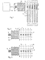
- FIGS. 1 to 5 illustrate a particular embodiment of this method.
- Figure 1 shows, schematically, an assembly 6 of five rows A, B, C, D and E of bars containing a fissile material 7 surmounted by a plenum 8 in which are collected these fission products which escape from fissile material during the operation of a nuclear reactor.
- a radiation detector 0 9 which is duely protected against the surrounding radiation, is arranged behind a collimator 10 of dimensions such that only the plenums of a row of bars at a time can be in the field of vision 11 of the detector 9.
- This field of vision or detection 11 has a pyramidal shape spread especially along the axis of the bars, as clearly shown in Figures 1 to 3.
- the loss of sensitivity of measurement of ⁇ -rays due to the distance of certain bars, is at least partially offset by this pyramidal shape of the beam of rays picked up by the detector and forming the aforementioned vision area 11.
- the more distant a determined bar the larger the plenum section located in the vision zone 11.
- the solid angle of the collimator is chosen so as to approximately compensate for the losses by absorption-y. We could thus adjust, in this regard, the dimension of the slot 12 of the collimator 10 along the axis of the bars.
- this slot 12 is imposed by the activity to be measured and the statistical precision. It will preferably be much smaller than the outside diameter of the bars in order to eliminate edge effects, such as arrows of the bars, centering of a spring not shown, etc.
- the ⁇ -9 radiation detector comprises, for example, a NaI, Ge (Li), intrinsic Ge, Cd.Te, HgI 2 , etc. crystal. It is connected to a measuring device 12 which is, for example, formed by an apparatus of recording of the total activity or of an apparatus for discriminating ⁇ -radiation of energies corresponding to very characteristic fission products, for example using a single-channel, a multi-channel, etc.
- a measuring device 12 which is, for example, formed by an apparatus of recording of the total activity or of an apparatus for discriminating ⁇ -radiation of energies corresponding to very characteristic fission products, for example using a single-channel, a multi-channel, etc.
- the choice of measurement method essentially depends on practical working conditions, in particular the type of assembly, the irradiation time, the cooling time, etc.
- Figures 1 to 3 illustrate a practical example of the location of a fleeing bar.
- This method consists in measuring separately and successively the activity ⁇ of the rows 1 to 5 of the assembly 6 extending in the direction of the arrow 14 by subjecting for example this assembly to a translation in the direction of the arrows 15 so that the plenums 8 of the bars of each of these rows 1 to 5 pass through the viewing area 11 of the collimator 10.
- the assembly of bars 6 is rotated by an angle of 90 ° around a parallel axis. to the bars as indicated by the arrow 16 in FIG. 3, so that the bars occupy the relative position relative to the collimator 10, as indicated in FIG. 3.
- This translation can be continuous or step by step.
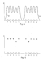
- the measurement of the activity- ⁇ can be plotted as a graph as shown in Figure 4. On the ordinate is given the activity- ⁇ , while on the abscissa we show the displacement of l assembly of bars opposite the collimator 10.
- Graph 18 shows the measurement carried out as illustrated in FIG. 2, while Graph 19 shows the measurement carried out, as illustrated in FIG. 3.
- the assembly includes a single fleeing bar being in position B4, the activities- ⁇ of rows 4 and B, which contain this bar, will indicate a variation of the activity- ⁇ , which is for example as shown in Figure 4, a decrease in ⁇ activity. Furthermore, by calculation, it is also possible to determine a variation in the ratio of one or more radioactive products.
- the distance between two successive steps must be substantially equal to that separating the axial planes of two consecutive rows of bars in the assembly.
- the detector can be fixed and, in this case, the collimator can be practiced in the wall 20 of the deactivation or storage tank or of the cell armored, which contains this assembly, at the level of the plenums 8 of the bars.
- This wall then constitutes the essential of the protection-lr of the detector 9.
- the collimator cannot be made in the wall for practical reasons, as a variant of the method for locating a leaking bar according to the invention, provision could be made for the translation of the assembly formed by the collimator 10, the detector 9 and a special protection of the detector against surrounding radiation.
- this assembly can for example cooperate with a mechanism not shown in the figures which allows the translation of this assembly inside the deactivation or storage tank or the shielded cell, for example along the inner face. of the wall 20 of the latter. It is therefore necessary, in the case of a square network, as shown in Figures 2 and 3, that said assembly can undergo two translations at right angles in a horizontal direction to the outside of the assembly of the bars.
- This assembly could even be immersed in the refrigerant contained in the aforementioned tank.
- the displacement of the assembly of bars could for example be limited to a simple rotation around an axis parallel to the bars and the translation of a detector-collimator assembly could be limited to a single direction.
- the above rotation of this assembly could be limited to 60 ° instead of 90 °, while in the case of a fixed assembly, the angle formed between the two translations of l the movable detector-collimator assembly should also be 60 °.
- the loss of sensitivity due to the distance from a determined bar can be compensated, at least partially, by the pyramidal shape of the field of vision of the collimator.
- the assembly 1 could be made for the assembly 1 to heat up during the measurement of the activity or between two measurements of the activity, so as to produce a larger leak, therefore easier to locate.
- the invention also relates to an installation for locating a leaking bar in a nuclear fuel assembly.
- such an installation comprises an enclosure (storage or deactivation tank or shielded cell) containing at least partially, an assembly of bars and at least one ray detector y placed behind a collimator of dimensions such that only the plenums of the bars are located in the detection or vision area of the detector.
- Figure 6 shows a particular embodiment of part of such an installation.
- a bottle 21 which can be placed above the assembly of bars 6 and at least partially immersed in the coolant 22 of the deactivation or storage tank, part of the protection ⁇ 20 has been shown where is provided the collimator 10 and the detector 9.
- This bottle is connected, by its upper part, to a source of pressurized gas, not shown, by a pipe 23, so as to allow the coolant to be removed below of the bottle to a level below the vision or detection zone 11, so as to reduce the absorption - r.
- the same effect could be obtained by heating the assembly.
- this embodiment with several detectors could be integrated into a penetrant installation mentioned above.
- the method according to the invention is not limited to the upper plenum as given above by way of example, but can be applied to the different plenums that the assembly to be examined whatever their levels.
- the bars are removable in the assemblies, so as to allow easy replacement of the leaking bars.
Landscapes
- Physics & Mathematics (AREA)
- Engineering & Computer Science (AREA)
- Plasma & Fusion (AREA)
- General Engineering & Computer Science (AREA)
- High Energy & Nuclear Physics (AREA)
- Monitoring And Testing Of Nuclear Reactors (AREA)
- Measurement Of Radiation (AREA)
Applications Claiming Priority (2)
| Application Number | Priority Date | Filing Date | Title |
|---|---|---|---|
| FR7917579 | 1979-07-06 | ||
| FR7917579A FR2461337A1 (fr) | 1979-07-06 | 1979-07-06 | Methode de localisation d'un barreau fuyard dans un assemblage de combustible nucleaire |
Publications (3)
| Publication Number | Publication Date |
|---|---|
| EP0022294A2 true EP0022294A2 (de) | 1981-01-14 |
| EP0022294A3 EP0022294A3 (en) | 1981-01-28 |
| EP0022294B1 EP0022294B1 (de) | 1983-03-23 |
Family
ID=9227596
Family Applications (1)
| Application Number | Title | Priority Date | Filing Date |
|---|---|---|---|
| EP80200622A Expired EP0022294B1 (de) | 1979-07-06 | 1980-07-01 | Verfahren und Anlage zum Lokalisieren eines undichten Brennstabes im Brennelementbündel |
Country Status (5)
| Country | Link |
|---|---|
| US (1) | US4353863A (de) |
| EP (1) | EP0022294B1 (de) |
| JP (1) | JPS5950956B2 (de) |
| DE (1) | DE3062429D1 (de) |
| FR (1) | FR2461337A1 (de) |
Cited By (3)
| Publication number | Priority date | Publication date | Assignee | Title |
|---|---|---|---|---|
| EP0147800A3 (de) * | 1983-12-27 | 1986-04-30 | Jerry D. Heald | Verfahren und Einrichtung zum Nachweis und Charakterisierung von Rissen |
| AU610451B2 (en) * | 1989-03-29 | 1991-05-16 | Winner International Royalty Llc | Vehicle security system |
| EP0684611A1 (de) * | 1994-05-27 | 1995-11-29 | Doryokuro Kakunenryo Kaihatsu Jigyodan | Verfahren zum Auffinden von fehlerhaftem Kernreaktorbrennstoff |
Families Citing this family (10)
| Publication number | Priority date | Publication date | Assignee | Title |
|---|---|---|---|---|
| JPS57201893A (en) * | 1981-06-08 | 1982-12-10 | Tokyo Shibaura Electric Co | Gamma scan device for fuel assembly |
| JPS6025492A (ja) * | 1983-07-22 | 1985-02-08 | 株式会社東芝 | 破損燃料棒検知装置 |
| US4650637A (en) * | 1984-02-14 | 1987-03-17 | Westinghouse Electric Corp. | Method and apparatus for locating a leaking fuel rod in an assembly containing many rods |
| JP2561082Y2 (ja) * | 1990-03-28 | 1998-01-28 | 日本精工株式会社 | ラックアンドピニオン式動力伝達装置に於けるピニオン軸の支持装置 |
| US7096600B2 (en) * | 2002-12-13 | 2006-08-29 | Holtec International, Inc. | Forced gas flow canister dehydration |
| GB0304721D0 (en) * | 2003-03-01 | 2003-04-02 | British Nuclear Fuels Plc | Improvements in and relating to measurement |
| GB0506079D0 (en) * | 2005-03-24 | 2005-05-04 | British Nuclear Fuels Plc | Improvements in and relating to providing information |
| JP2012173077A (ja) * | 2011-02-21 | 2012-09-10 | Mitsubishi Heavy Ind Ltd | 加熱装置 |
| CN115691843A (zh) * | 2022-11-15 | 2023-02-03 | 中国船舶重工集团公司第七一九研究所 | 一种压水反应堆一回路承压边界泄漏定位监测系统及方法 |
| CN120072368A (zh) * | 2025-02-20 | 2025-05-30 | 中广核工程有限公司 | 用于核燃料破损检测的示踪物及核燃料破损检测方法 |
Family Cites Families (17)
| Publication number | Priority date | Publication date | Assignee | Title |
|---|---|---|---|---|
| US2777812A (en) * | 1952-03-12 | 1957-01-15 | Robert W Powell | Leak detection system |
| NL255879A (de) * | 1959-10-03 | |||
| NL264839A (de) * | 1960-05-20 | 1900-01-01 | ||
| GB989393A (en) * | 1962-11-20 | 1965-04-14 | Atomic Energy Authority Uk | Improvements in or relating to nuclear reactor fuel elements |
| FR1383186A (fr) * | 1962-11-20 | 1964-12-24 | Atomic Energy Authority Uk | Cartouche de combustible pour réacteur nucléaire |
| US3663363A (en) * | 1969-03-13 | 1972-05-16 | Atomic Energy Commission | Identification of failed fuel elements |
| AR204231A1 (es) * | 1970-04-04 | 1975-12-10 | Siemens Ag | Dispositivo para la determinacion no destructiva de consumo de elementos combustibles de reactores nucleares |
| US3813286A (en) * | 1972-05-08 | 1974-05-28 | Transfer Systems | Fuel element with failure indicator |
| US3975949A (en) * | 1974-01-10 | 1976-08-24 | Exxon Nuclear Company, Inc. | Leak detector probe for fuel rods |
| US3904042A (en) | 1974-02-25 | 1975-09-09 | Westinghouse Electric Corp | Manipulator apparatus |
| AT340013B (de) * | 1975-02-25 | 1977-11-25 | Interatom | Verfahren zur lokalisierung von defekten an brennstaben von reaktorbrennelementen |
| GB1499113A (en) * | 1975-11-25 | 1978-01-25 | Atomic Energy Authority Uk | Methods of estimating one radioactive substance in the presence of another |
| JPS52106096A (en) * | 1976-03-03 | 1977-09-06 | Hitachi Ltd | Broken fuel detecting method |
| DE2610046A1 (de) * | 1976-03-11 | 1977-09-15 | Interatom | Kapsel fuer das einbringen von markierungsstoffen in kernreaktoren |
| US4172760A (en) * | 1976-12-06 | 1979-10-30 | General Electric Company | Neutron transmission testing apparatus and method |
| FR2389202A1 (fr) * | 1977-04-29 | 1978-11-24 | Framatome Sa | Cellule de ressuage pour le controle de l'etancheite d'assemblages d'elements combustibles et procede de controle correspondant |
| FR2395571A1 (fr) * | 1977-06-23 | 1979-01-19 | Framatome Sa | Dispositif de manipulation et d'examen de crayons amovibles d'assemblages combustibles |
-
1979
- 1979-07-06 FR FR7917579A patent/FR2461337A1/fr active Pending
-
1980
- 1980-07-01 DE DE8080200622T patent/DE3062429D1/de not_active Expired
- 1980-07-01 EP EP80200622A patent/EP0022294B1/de not_active Expired
- 1980-07-03 US US06/165,812 patent/US4353863A/en not_active Expired - Lifetime
- 1980-07-04 JP JP55092179A patent/JPS5950956B2/ja not_active Expired
Cited By (3)
| Publication number | Priority date | Publication date | Assignee | Title |
|---|---|---|---|---|
| EP0147800A3 (de) * | 1983-12-27 | 1986-04-30 | Jerry D. Heald | Verfahren und Einrichtung zum Nachweis und Charakterisierung von Rissen |
| AU610451B2 (en) * | 1989-03-29 | 1991-05-16 | Winner International Royalty Llc | Vehicle security system |
| EP0684611A1 (de) * | 1994-05-27 | 1995-11-29 | Doryokuro Kakunenryo Kaihatsu Jigyodan | Verfahren zum Auffinden von fehlerhaftem Kernreaktorbrennstoff |
Also Published As
| Publication number | Publication date |
|---|---|
| EP0022294A3 (en) | 1981-01-28 |
| EP0022294B1 (de) | 1983-03-23 |
| DE3062429D1 (en) | 1983-04-28 |
| JPS5950956B2 (ja) | 1984-12-11 |
| FR2461337A1 (fr) | 1981-01-30 |
| US4353863A (en) | 1982-10-12 |
| JPS5619494A (en) | 1981-02-24 |
Similar Documents
| Publication | Publication Date | Title |
|---|---|---|
| EP0022294B1 (de) | Verfahren und Anlage zum Lokalisieren eines undichten Brennstabes im Brennelementbündel | |
| EP0307271B1 (de) | Vorrichtung zur Charakterisierung von spaltbarem Material, welche einen im Innern eines Gammastrahlungsdetektionsszintillators eingebetteten Neutronenstrahlungsdetektor enthält | |
| FR2521763A1 (fr) | Appareil et procede pour enlever et remplacer des barres de combustible dans un assemblage combustible nucleaire | |
| EP0473489A1 (de) | Verfahren zur Kontrolle des Aufsetzens eines transportierbaren Elements and Kontrolle der Verbindungsdichtheit mit einer festen Struktur und Anwendung dieses Verfahrens | |
| EP0307302B1 (de) | Vorrichtung zur Überwachung des kritischen Zustandes und Messung der Konzentration spaltbarer Massen | |
| FR2700058A1 (fr) | Elément constituant interne d'un réacteur de fusion. | |
| EP3583610B1 (de) | Vorrichtung und verfahren zur versiegelungsprüfung durch penetrierende inspektion eines kernbrennstabbündels | |
| EP0551783B1 (de) | Verfahren und Vorrichtung zur zerstörungsfreien Prüfung einer Wand eines mit einer radioaktiven Flüssigkeit gefüllten Behälters | |
| BE1008007A3 (fr) | Procede et dispositif de detection de fuite sur un element combustible d'un assemblage pour reacteur nucleaire. | |
| CH665919A5 (fr) | Dispositif de fermeture de chateau de stockage de combustible nucleaire use. | |
| EP0604618A1 (de) | Vorrichtung zur anzeige des leckflusses in einem primärkreislauf eines kernreaktors | |
| EP0098208A1 (de) | Apparat zur Messung des Wasserniveaus in einem geschlossenen Raum | |
| FR2632441A1 (fr) | Procede et dispositif de controle des parois laterales d'un alveole de stockage d'un assemblage combustible | |
| FR2509898A1 (fr) | Procede de detection rapide d'une fissure dans la gaine d'un crayon combustible d'un assemblage de reacteur nucleaire | |
| EP0070758B1 (de) | Dampferzeuger mit einer Vorrichtung zur Ermittlung von Undichtheiten | |
| EP0329554B1 (de) | Verfahren und Einrichtung zum Auffinden undichter Stäbe in einer Kernbrennelementanordnung | |
| FR2752639A1 (fr) | Dispositif de caracterisation individuelle d'assemblages de combustible nucleaire et installation de controle non destructif comprenant un tel dispositif | |
| FR2746538A1 (fr) | Procede et dispositif de detection d'assemblages de combustible ou de grappes de commande d'un reacteur nucleaire accroches en-dessous d'equipements internes superieurs du reacteur | |
| FR2523723A1 (fr) | Procede de detection d'une baisse de pression interne de gaz dans les produits du type recipient | |
| FR3086789A1 (fr) | Reacteur nucleaire a sel fondu | |
| EP0064462A1 (de) | Schneller Kernreaktor mit einem aus Brennstabbündeln bestehenden Kern und Einrichtung zur Lokalisierung defekter Brennstabbündel | |
| FR2803426A1 (fr) | Installation et procede d'entreposage de produits irradies et notamment d'assemblages de combustible nucleaire irradies | |
| FR2642887A1 (fr) | Assemblage combustible | |
| WO2026003222A1 (fr) | Centrale nucléaire à bâtiment nucléaire logeant au moins un réacteur nucléaire à sel(s) fondu(s), de type à neutrons rapides et un système de gestion des gaz de fission accumulés dans le ciel de pile du réacteur | |
| WO2022194990A1 (fr) | Dispositif pour monter ou descendre un assemblage de combustible nucléaire dans une piscine d'une installation nucléaire |
Legal Events
| Date | Code | Title | Description |
|---|---|---|---|
| PUAI | Public reference made under article 153(3) epc to a published international application that has entered the european phase |
Free format text: ORIGINAL CODE: 0009012 |
|
| PUAL | Search report despatched |
Free format text: ORIGINAL CODE: 0009013 |
|
| AK | Designated contracting states |
Designated state(s): BE CH DE FR GB IT NL SE |
|
| AK | Designated contracting states |
Designated state(s): BE CH DE FR GB IT NL SE |
|
| 17P | Request for examination filed |
Effective date: 19810302 |
|
| GRAA | (expected) grant |
Free format text: ORIGINAL CODE: 0009210 |
|
| AK | Designated contracting states |
Designated state(s): BE CH DE FR GB IT LI NL SE |
|
| PG25 | Lapsed in a contracting state [announced via postgrant information from national office to epo] |
Ref country code: SE Effective date: 19830323 Ref country code: IT Free format text: LAPSE BECAUSE OF FAILURE TO SUBMIT A TRANSLATION OF THE DESCRIPTION OR TO PAY THE FEE WITHIN THE PRESCRIBED TIME-LIMIT;WARNING: LAPSES OF ITALIAN PATENTS WITH EFFECTIVE DATE BEFORE 2007 MAY HAVE OCCURRED AT ANY TIME BEFORE 2007. THE CORRECT EFFECTIVE DATE MAY BE DIFFERENT FROM THE ONE RECORDED. Effective date: 19830323 |
|
| REF | Corresponds to: |
Ref document number: 3062429 Country of ref document: DE Date of ref document: 19830428 |
|
| PGFP | Annual fee paid to national office [announced via postgrant information from national office to epo] |
Ref country code: FR Payment date: 19840524 Year of fee payment: 5 |
|
| PGFP | Annual fee paid to national office [announced via postgrant information from national office to epo] |
Ref country code: CH Payment date: 19840619 Year of fee payment: 5 |
|
| PGFP | Annual fee paid to national office [announced via postgrant information from national office to epo] |
Ref country code: DE Payment date: 19840816 Year of fee payment: 5 |
|
| PGFP | Annual fee paid to national office [announced via postgrant information from national office to epo] |
Ref country code: NL Payment date: 19870731 Year of fee payment: 8 |
|
| PG25 | Lapsed in a contracting state [announced via postgrant information from national office to epo] |
Ref country code: GB Effective date: 19880701 |
|
| PG25 | Lapsed in a contracting state [announced via postgrant information from national office to epo] |
Ref country code: LI Effective date: 19880731 Ref country code: CH Effective date: 19880731 |
|
| PG25 | Lapsed in a contracting state [announced via postgrant information from national office to epo] |
Ref country code: NL Effective date: 19890201 |
|
| GBPC | Gb: european patent ceased through non-payment of renewal fee | ||
| NLV4 | Nl: lapsed or anulled due to non-payment of the annual fee | ||
| PG25 | Lapsed in a contracting state [announced via postgrant information from national office to epo] |
Ref country code: FR Free format text: LAPSE BECAUSE OF NON-PAYMENT OF DUE FEES Effective date: 19890331 |
|
| REG | Reference to a national code |
Ref country code: CH Ref legal event code: PL |
|
| PG25 | Lapsed in a contracting state [announced via postgrant information from national office to epo] |
Ref country code: DE Effective date: 19890401 |
|
| REG | Reference to a national code |
Ref country code: FR Ref legal event code: ST |
|
| PGFP | Annual fee paid to national office [announced via postgrant information from national office to epo] |
Ref country code: BE Payment date: 19950818 Year of fee payment: 16 |
|
| PG25 | Lapsed in a contracting state [announced via postgrant information from national office to epo] |
Ref country code: BE Effective date: 19960731 |
|
| BERE | Be: lapsed |
Owner name: CENTRE D'ETUDE DE L'ENERGIE NUCLEAIRE CEN Effective date: 19960731 |
|
| PLBE | No opposition filed within time limit |
Free format text: ORIGINAL CODE: 0009261 |
|
| STAA | Information on the status of an ep patent application or granted ep patent |
Free format text: STATUS: NO OPPOSITION FILED WITHIN TIME LIMIT |