EP0022657B1 - Articulation pour fenêtres pivotantes, en particulier pour fenêtres tabatières inclinées - Google Patents
Articulation pour fenêtres pivotantes, en particulier pour fenêtres tabatières inclinées Download PDFInfo
- Publication number
- EP0022657B1 EP0022657B1 EP80302322A EP80302322A EP0022657B1 EP 0022657 B1 EP0022657 B1 EP 0022657B1 EP 80302322 A EP80302322 A EP 80302322A EP 80302322 A EP80302322 A EP 80302322A EP 0022657 B1 EP0022657 B1 EP 0022657B1
- Authority
- EP
- European Patent Office
- Prior art keywords
- base plate
- sash
- pivot pin
- guide
- pin
- Prior art date
- Legal status (The legal status is an assumption and is not a legal conclusion. Google has not performed a legal analysis and makes no representation as to the accuracy of the status listed.)
- Expired
Links
- 238000006073 displacement reaction Methods 0.000 claims abstract description 13
- 238000010276 construction Methods 0.000 description 2
- 230000001419 dependent effect Effects 0.000 description 2
- 239000002184 metal Substances 0.000 description 2
- 101150034459 Parpbp gene Proteins 0.000 description 1
- 238000013459 approach Methods 0.000 description 1
- 238000009434 installation Methods 0.000 description 1
- 230000000414 obstructive effect Effects 0.000 description 1
- 230000000149 penetrating effect Effects 0.000 description 1
Images
Classifications
-
- E—FIXED CONSTRUCTIONS
- E05—LOCKS; KEYS; WINDOW OR DOOR FITTINGS; SAFES
- E05D—HINGES OR SUSPENSION DEVICES FOR DOORS, WINDOWS OR WINGS
- E05D7/00—Hinges or pivots of special construction
- E05D7/08—Hinges or pivots of special construction for use in suspensions comprising two spigots placed at opposite edges of the wing, especially at the top and the bottom, e.g. trunnions
- E05D7/082—Hinges or pivots of special construction for use in suspensions comprising two spigots placed at opposite edges of the wing, especially at the top and the bottom, e.g. trunnions the pivot axis of the wing being situated at a considerable distance from the edges of the wing, e.g. for balanced wings
- E05D7/084—Hinges or pivots of special construction for use in suspensions comprising two spigots placed at opposite edges of the wing, especially at the top and the bottom, e.g. trunnions the pivot axis of the wing being situated at a considerable distance from the edges of the wing, e.g. for balanced wings with a movable pivot axis
- E05D7/085—Hinges or pivots of special construction for use in suspensions comprising two spigots placed at opposite edges of the wing, especially at the top and the bottom, e.g. trunnions the pivot axis of the wing being situated at a considerable distance from the edges of the wing, e.g. for balanced wings with a movable pivot axis with two or more pivot axes, e.g. used at the same time
-
- E—FIXED CONSTRUCTIONS
- E05—LOCKS; KEYS; WINDOW OR DOOR FITTINGS; SAFES
- E05Y—INDEXING SCHEME ASSOCIATED WITH SUBCLASSES E05D AND E05F, RELATING TO CONSTRUCTION ELEMENTS, ELECTRIC CONTROL, POWER SUPPLY, POWER SIGNAL OR TRANSMISSION, USER INTERFACES, MOUNTING OR COUPLING, DETAILS, ACCESSORIES, AUXILIARY OPERATIONS NOT OTHERWISE PROVIDED FOR, APPLICATION THEREOF
- E05Y2900/00—Application of doors, windows, wings or fittings thereof
- E05Y2900/10—Application of doors, windows, wings or fittings thereof for buildings or parts thereof
- E05Y2900/13—Type of wing
- E05Y2900/148—Windows
- E05Y2900/152—Roof windows
- E05Y2900/154—Skylights
Definitions
- Windows of the tiltable type in particular of the kind adapted to be installed in sloping roofs must satisfy heavy demands with respect to weathertightness and in general they therefore comprise an inner rabbet or abutment fillet aiming particularly at eliminating draught, and an external metallic or plastic covering primarily intended to prevent rainwater from penetrating between the stationary frame and the sash of the window.
- the rabbet or fillet as well as the outer covering are necessarily divided at the pivot axis, i.e. in the areas of the hinge devices, the portions of the fillet and covering above the axis being secured to the frame, while the portions below the axis are mounted on the sash so as to follow the movements thereof.
- a condition of an optimum tightness is that the rabbet or fillet forms a tight closure below the hinges, thereby restricting the permissible depth of the hinges, i.e. their dimension perpendicular to the plane of the window, but it is even more important that the hinges guide the sash so as to allow a sufficient overlapping, in the closed position of the window, between the movable and non-movable parts of the outer covering without causing these parts to prevent a tilting of the window sash through approximately 180°, or without causing the parts to be damaged by such a movement of the sash.
- the sash should moreover be balanced in such a manner that at least within certain open positions it remains immovable in any angular position in relation to the stationary frame, and it should further be easily mounted in and dismounted from the frame, for instance in order to change its pane.
- a hinge device of the kind illustrated in Figs. 6 and 7 of British patent specification no. 1,028,251 apart from the fact that it may be difficult to control the frictional properties of the arc-shaped sliding rails and guides of this hinge and, consequently, to control the balancing conditions of the window sash when this sash shall also be reasonably easy to open and close.
- the prior art hinge in practice must include a large number of details which may well be produced relatively cheaply, but still they require rather expensive stamping tools and many assembling operations.
- DE-B-1,162,224, DE-A-2,132,085 and DE-A-1,708,123 all disclose arrangements in which the various guide members of the hinge device move primarily by rotation as the sash is tilted in the frame. These arrangements are not suitable for inclined windows where movable and non-movable parts of an outer covering overlap in the closed position of the window.
- the present invention relates to a hinge device for tilting windows, in particular inclined skylights or overhead windows, and comprising a hinge mechanism having base plates to be mounted on the window frame and its sash, respectively, and guide means defining a tilting axis to determine the movement of the sash in the vicinity of its closed position, said axis being spaced outwardly from the plane of the window, and the sash when remote from the closed position being tiltable in relation to the frame about a pivot pin, which by the initial opening movement of the sash about the said outwardly spaced axis is moved from a poisition within the thickness of the window to a position spaced outwardly therefrom.
- the hinge according to the invention differs from the prior art design in that the pivot pin is carried by a guide member which is connected to a first one of the base plates in such a manner as to be mainly translatorily displaceable in relation to the first base plate and in that the second base plate is provided with a guide-pin co-operating with a guide on the first base plate so as to co-ordinate the tilting movement of the second base plate about the pivot pin with the mainly translatory displacement of said pivot pin.
- the guide member may be a simple blank stamped out from metal sheet, and also its connection to the base plate of the hinge portion concerned may be obtained in a structurally simple manner, e.g. by means of a pair of links or straps as more fully explained in the following. It is hereby made possible, within the confined space dependent on the maximum depth of the hinge, to adapt the movement of the guide member according to desire. This implies that, contrary to what is the case of the above mentioned prior construction, the pivot pin does not necessarily have to follow an arc between its two extreme positions, i.e. within and outside the thickness of the window, resp.
- the condition of a correct operation of the hinge device is that the displacement of the guide member and the tilting of the sash about the pivot pin are co-ordinated so that the movement of the pivot pin until it occupies its outer extreme position is uniquely dependent on the tilting movement of the sash.
- the pivot pin shall be displaced in the direction towards its outer and inner extreme positions pari passu with the movement of the sash away from and towards its closed position.
- the said guide pin which is capable of co-operating with stationary and/or movable guide paths so as to be co-responsible for the movement of the sash in relation to the stationary frame.
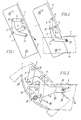
- Fig. 1 shows only the frame portion of the hinge device which comprises a base plate 1 provided with screw holes 2.
- This hinge portion is supposed to be mounted in a stationary frame, not shown, so that its front edge is substantially flush with the outer surface of the frame to which a plate covering 3 is secured which extends from the top downwards to the hinge area where it overlaps a corresponding covering 4 on the movable sash, not shown.
- the initial opening movement of the sash is directed substantially along the arrow thereby causing the sash covering 4 to get clear of the frame covering 3.
- This movement may be regarded as a displacement downwards and outwards in relation to the frame combined with a controlled pivoting or tilting of the sash although Figs. 1 and 2 only show the mechanism serving to guide the displacement.
- the said mechanism incorporates only three elements, viz. a guide member 5 in the form of an angular blank stamped out from sheet metal, and two more or less parallel links or straps 6 and 7 which at one end are connected with the base plate 1 adjacent its front edge through hinge pins 8 and 9 and at their other end are rotatably connected through pins 10 and 11 with the guide member 5 at its upper end and in the vicinity of its centre, resp.
- the member 5 has a hole 12 serving as a bearing for the pivot pin 13, Fig. 2, of the sash.
- This pivot pin 13 is secured to a base plate 14 that may have the same contour as the base plate 1 of the frame portion.
- the lengths of the links 6 and 7 and the locations of their pivot points 8 to 11 may be chosen so that, within certain limits, the path of the mainly translatory displacement of the guide member 5 between the positions in Figs 1 and 2 can be determined as desired.
- One or each of the links 6 and 7 could be substituted by a guide pin and an associated guiding track to determine the movement of the member 5, but in this case it might be more difficult to control the frictional properties of the hinge.
- Fig. 3 shows a fragmentary view of a complete hinge, the frame portion being shown in full lines while the sash portion is shown in dot-and-dash lines in an intermediate position.
- the same reference numerals as in Figs. 1 and 2 are used for analogous parts.
- the pivot pin 13 journalled in the guide member 5 is fixedly secured to the base plate 14 of the sash portion, but also a guide pin 15 serving to co-ordinate the rotation or tilting of the sash about the pivot pin 13 with the displacement of the guide member 5.
- the V-shaped recess 22 in the guide member 5 serves to provide space for the guide pin 15 during the final part of its movement when the window is being closed. If the guiding rail 16 during this final movement be obstructive to the members 5, 6 and 7 it may be provided with necessary recesses to allow their unobstructed movement. Such a recess 23 for the link 6 is shown at the upper end of the guiding rail 16.
Landscapes
- Engineering & Computer Science (AREA)
- Mechanical Engineering (AREA)
- Hinges (AREA)
- Roof Covering Using Slabs Or Stiff Sheets (AREA)
- Closing And Opening Devices For Wings, And Checks For Wings (AREA)
- Window Of Vehicle (AREA)
- Vehicle Interior And Exterior Ornaments, Soundproofing, And Insulation (AREA)
- Working Measures On Existing Buildindgs (AREA)
Claims (4)
Priority Applications (1)
| Application Number | Priority Date | Filing Date | Title |
|---|---|---|---|
| AT80302322T ATE6288T1 (de) | 1979-07-10 | 1980-07-09 | Scharnierbeschlag fuer kippfenster, insbesondere schraege dachfenster. |
Applications Claiming Priority (2)
| Application Number | Priority Date | Filing Date | Title |
|---|---|---|---|
| DK290479A DK144771C (da) | 1979-07-10 | 1979-07-10 | Haengselbeslag til vippevinduer,navnlig skraat indbyggede tagvinduer |
| DK2904/79 | 1979-07-10 |
Publications (2)
| Publication Number | Publication Date |
|---|---|
| EP0022657A1 EP0022657A1 (fr) | 1981-01-21 |
| EP0022657B1 true EP0022657B1 (fr) | 1984-02-15 |
Family
ID=8116958
Family Applications (1)
| Application Number | Title | Priority Date | Filing Date |
|---|---|---|---|
| EP80302322A Expired EP0022657B1 (fr) | 1979-07-10 | 1980-07-09 | Articulation pour fenêtres pivotantes, en particulier pour fenêtres tabatières inclinées |
Country Status (6)
| Country | Link |
|---|---|
| US (1) | US4366597A (fr) |
| EP (1) | EP0022657B1 (fr) |
| JP (1) | JPS5612477A (fr) |
| AT (1) | ATE6288T1 (fr) |
| DE (1) | DE3066582D1 (fr) |
| DK (1) | DK144771C (fr) |
Cited By (6)
| Publication number | Priority date | Publication date | Assignee | Title |
|---|---|---|---|---|
| WO2017076416A1 (fr) | 2015-11-06 | 2017-05-11 | Vkr Holding A/S | Charnière pour lucarne et lucarne comprenant un ensemble de charnières |
| EP3299536A1 (fr) | 2016-09-23 | 2018-03-28 | VKR Holding A/S | Fenêtre de toit comprenant un ensemble de charnières ayant une séquence de mouvement améliorée |
| WO2018202915A1 (fr) | 2017-05-05 | 2018-11-08 | Vkr Holding A/S | Charnière pour une fenêtre, fenêtre comprenant un ensemble de telles charnières, et procédé d'installation d'une telle fenêtre |
| WO2022228634A1 (fr) | 2021-04-29 | 2022-11-03 | Vkr Holding A/S | Charnière pour fenêtre de toit et fenêtre de toit comprenant un ensemble de charnières |
| WO2022228633A1 (fr) | 2021-04-29 | 2022-11-03 | Vkr Holding A/S | Charnière pour fenêtre de toit et fenêtre de toit dotée d'un ensemble de charnières |
| WO2022228632A1 (fr) | 2021-04-29 | 2022-11-03 | Vkr Holding A/S | Charnière pour une fenêtre de toit et fenêtre de toit avec un ensemble de charnières |
Families Citing this family (6)
| Publication number | Priority date | Publication date | Assignee | Title |
|---|---|---|---|---|
| DK146397C (da) * | 1981-07-03 | 1984-03-05 | Rasmussen Holding As V Kann | Haengselbeslag til skraat indbyggede vippevinduer med udvendige daekskinner |
| EP0456081B1 (fr) * | 1990-04-30 | 1994-06-29 | Anthony Charles Sandell | Charnière apte pour l'utilisation dans un montage de lucarne |
| US7565720B1 (en) * | 2005-04-01 | 2009-07-28 | Apple Inc. | Hinge mechanism with clutching function |
| CZ308102B6 (cs) | 2018-10-31 | 2020-01-02 | Univerzita Karlova | Postnatální epigenetický profil kardiovaskulárních mikroRNA u dětí narozených z komplikovaných gravidit - nové biomarkery kardiovaskulárního rizika |
| CZ308178B6 (cs) | 2018-10-31 | 2020-02-05 | Univerzita Karlova | Postpartální epigenetický profil kardiovaskulárních mikroRNA u matek po komplikované graviditě - nové biomarkery kardiovaskulárního rizika |
| DK181849B1 (en) | 2021-04-29 | 2025-02-19 | Vkr Holding As | Roof window with a set of hinges |
Family Cites Families (7)
| Publication number | Priority date | Publication date | Assignee | Title |
|---|---|---|---|---|
| US2100928A (en) * | 1935-06-21 | 1937-11-30 | Walter R Way | Closure for wall openings |
| DE1162224B (de) * | 1957-06-24 | 1964-01-30 | Friedrich Puchtler | Lager fuer Schwingfluegelfenster |
| US3028621A (en) * | 1960-03-09 | 1962-04-10 | A W Anderberg Mfg Co | Window mounting device |
| DK99616C (da) | 1963-01-31 | 1964-08-24 | Rasmussen V B K | Hængselbeslag til dreje- og vippevinduer. |
| DE1708123A1 (de) * | 1967-01-19 | 1970-04-30 | Leo Beck | Schwingfluegellager mit pendelnder Aufhaengung |
| DE2132085A1 (de) * | 1971-06-28 | 1973-01-18 | Hautau Baubeschlag | Schwinglager |
| IE48170B1 (en) * | 1977-09-30 | 1984-10-17 | Interlock Ind Ltd | Improvements in window or the like stays |
-
1979
- 1979-07-10 DK DK290479A patent/DK144771C/da not_active IP Right Cessation
-
1980
- 1980-06-16 US US06/159,462 patent/US4366597A/en not_active Expired - Lifetime
- 1980-06-16 JP JP8031580A patent/JPS5612477A/ja active Pending
- 1980-07-09 AT AT80302322T patent/ATE6288T1/de active
- 1980-07-09 EP EP80302322A patent/EP0022657B1/fr not_active Expired
- 1980-07-09 DE DE8080302322T patent/DE3066582D1/de not_active Expired
Cited By (10)
| Publication number | Priority date | Publication date | Assignee | Title |
|---|---|---|---|---|
| WO2017076416A1 (fr) | 2015-11-06 | 2017-05-11 | Vkr Holding A/S | Charnière pour lucarne et lucarne comprenant un ensemble de charnières |
| EP3702564A1 (fr) | 2015-11-06 | 2020-09-02 | VKR Holding A/S | Charnière pour une fenêtre de toit et fenêtre de toit comprenant un ensemble de charnières |
| EP3702563A1 (fr) | 2015-11-06 | 2020-09-02 | VKR Holding A/S | Charnière pour une fenêtre de toit et fenêtre de toit comprenant un ensemble de charnières |
| EP3299536A1 (fr) | 2016-09-23 | 2018-03-28 | VKR Holding A/S | Fenêtre de toit comprenant un ensemble de charnières ayant une séquence de mouvement améliorée |
| WO2018202915A1 (fr) | 2017-05-05 | 2018-11-08 | Vkr Holding A/S | Charnière pour une fenêtre, fenêtre comprenant un ensemble de telles charnières, et procédé d'installation d'une telle fenêtre |
| WO2022228634A1 (fr) | 2021-04-29 | 2022-11-03 | Vkr Holding A/S | Charnière pour fenêtre de toit et fenêtre de toit comprenant un ensemble de charnières |
| WO2022228633A1 (fr) | 2021-04-29 | 2022-11-03 | Vkr Holding A/S | Charnière pour fenêtre de toit et fenêtre de toit dotée d'un ensemble de charnières |
| WO2022228632A1 (fr) | 2021-04-29 | 2022-11-03 | Vkr Holding A/S | Charnière pour une fenêtre de toit et fenêtre de toit avec un ensemble de charnières |
| EP4365396A2 (fr) | 2021-04-29 | 2024-05-08 | VKR Holding A/S | Charnière pour fenêtre de toit et fenêtre de toit dotée d'un ensemble de charnières |
| EP4365398A2 (fr) | 2021-04-29 | 2024-05-08 | VKR Holding A/S | Charnière pour fenêtre de toit et fenêtre de toit dotée d'un ensemble de charnières |
Also Published As
| Publication number | Publication date |
|---|---|
| ATE6288T1 (de) | 1984-03-15 |
| DK290479A (da) | 1981-01-11 |
| DK144771B (da) | 1982-06-01 |
| JPS5612477A (en) | 1981-02-06 |
| DE3066582D1 (en) | 1984-03-22 |
| US4366597A (en) | 1983-01-04 |
| DK144771C (da) | 1982-10-25 |
| EP0022657A1 (fr) | 1981-01-21 |
Similar Documents
| Publication | Publication Date | Title |
|---|---|---|
| EP0022657B1 (fr) | Articulation pour fenêtres pivotantes, en particulier pour fenêtres tabatières inclinées | |
| CA1091113A (fr) | Charnieres de four avec cames de reglage d'angle d'ouverture | |
| US5964011A (en) | Adjustable casement window hinge | |
| EP0112681B1 (fr) | Entrebailleurs du type à friction | |
| US4790106A (en) | Cam adjustment device | |
| US5152102A (en) | Cam adjustment device for adjustable casement sash unit | |
| NO165453B (no) | Lamellport for lave fallhoeyder. | |
| US20170152690A1 (en) | Door or window hinge | |
| US4698877A (en) | Cabinet hinge | |
| CA2332484A1 (fr) | Charniere reglable | |
| US4727622A (en) | Hinge | |
| US4446597A (en) | Hinge device for inclined tilting type windows with external cover rails | |
| US5093960A (en) | Window hinge hat | |
| EP1290304B1 (fr) | Paumelle pour fenetres pivotantes | |
| EP0456081B1 (fr) | Charnière apte pour l'utilisation dans un montage de lucarne | |
| US4385551A (en) | Fume hood with sash lock | |
| US4359805A (en) | Window sash hinge | |
| GB2221721A (en) | Improvements in or relating to stay hinges | |
| NO178043B (no) | Beslag for blad i vinduer eller lignende, som er vippbare eller dreibare 180 | |
| US20080099163A1 (en) | Overhead door sealing apparatus | |
| US2126418A (en) | Sectional door | |
| GB2209051A (en) | Friction stay hinge | |
| US3842541A (en) | Window regulator mechanism for a vehicle | |
| US20040261320A1 (en) | Casement window operator system | |
| GB2236798A (en) | Improvements in or relating to friction stay-hinges |
Legal Events
| Date | Code | Title | Description |
|---|---|---|---|
| PUAI | Public reference made under article 153(3) epc to a published international application that has entered the european phase |
Free format text: ORIGINAL CODE: 0009012 |
|
| AK | Designated contracting states |
Designated state(s): AT BE CH DE FR GB IT LI NL SE |
|
| 17P | Request for examination filed |
Effective date: 19810610 |
|
| ITF | It: translation for a ep patent filed | ||
| GRAA | (expected) grant |
Free format text: ORIGINAL CODE: 0009210 |
|
| RBV | Designated contracting states (corrected) |
Designated state(s): AT BE CH DE FR GB IT LI NL SE |
|
| AK | Designated contracting states |
Designated state(s): AT BE CH DE FR GB IT LI NL SE |
|
| REF | Corresponds to: |
Ref document number: 6288 Country of ref document: AT Date of ref document: 19840315 Kind code of ref document: T |
|
| REF | Corresponds to: |
Ref document number: 3066582 Country of ref document: DE Date of ref document: 19840322 |
|
| ET | Fr: translation filed | ||
| PGFP | Annual fee paid to national office [announced via postgrant information from national office to epo] |
Ref country code: CH Payment date: 19840614 Year of fee payment: 5 |
|
| PGFP | Annual fee paid to national office [announced via postgrant information from national office to epo] |
Ref country code: BE Payment date: 19840630 Year of fee payment: 5 |
|
| PLBI | Opposition filed |
Free format text: ORIGINAL CODE: 0009260 |
|
| 26 | Opposition filed |
Opponent name: WILH. FRANK GMBH Effective date: 19841114 |
|
| NLR1 | Nl: opposition has been filed with the epo |
Opponent name: WILH. FRANK GMBH. |
|
| PLBN | Opposition rejected |
Free format text: ORIGINAL CODE: 0009273 |
|
| STAA | Information on the status of an ep patent application or granted ep patent |
Free format text: STATUS: OPPOSITION REJECTED |
|
| 27O | Opposition rejected |
Effective date: 19851118 |
|
| NLR2 | Nl: decision of opposition | ||
| PG25 | Lapsed in a contracting state [announced via postgrant information from national office to epo] |
Ref country code: LI Effective date: 19860731 Ref country code: CH Effective date: 19860731 Ref country code: BE Effective date: 19860731 |
|
| BERE | Be: lapsed |
Owner name: RASMUSSEN VILLUM BENEDIKT KANN Effective date: 19860731 |
|
| REG | Reference to a national code |
Ref country code: CH Ref legal event code: PL |
|
| EAL | Se: european patent in force in sweden |
Ref document number: 80302322.5 |
|
| PGFP | Annual fee paid to national office [announced via postgrant information from national office to epo] |
Ref country code: SE Payment date: 19960627 Year of fee payment: 17 |
|
| PGFP | Annual fee paid to national office [announced via postgrant information from national office to epo] |
Ref country code: GB Payment date: 19960628 Year of fee payment: 17 |
|
| PGFP | Annual fee paid to national office [announced via postgrant information from national office to epo] |
Ref country code: FR Payment date: 19960705 Year of fee payment: 17 |
|
| PGFP | Annual fee paid to national office [announced via postgrant information from national office to epo] |
Ref country code: AT Payment date: 19960725 Year of fee payment: 17 |
|
| PGFP | Annual fee paid to national office [announced via postgrant information from national office to epo] |
Ref country code: NL Payment date: 19960731 Year of fee payment: 17 |
|
| PGFP | Annual fee paid to national office [announced via postgrant information from national office to epo] |
Ref country code: DE Payment date: 19960927 Year of fee payment: 17 |
|
| PG25 | Lapsed in a contracting state [announced via postgrant information from national office to epo] |
Ref country code: GB Free format text: LAPSE BECAUSE OF NON-PAYMENT OF DUE FEES Effective date: 19970709 Ref country code: AT Free format text: LAPSE BECAUSE OF NON-PAYMENT OF DUE FEES Effective date: 19970709 |
|
| PG25 | Lapsed in a contracting state [announced via postgrant information from national office to epo] |
Ref country code: SE Effective date: 19970710 |
|
| PG25 | Lapsed in a contracting state [announced via postgrant information from national office to epo] |
Ref country code: NL Free format text: LAPSE BECAUSE OF NON-PAYMENT OF DUE FEES Effective date: 19980201 |
|
| GBPC | Gb: european patent ceased through non-payment of renewal fee |
Effective date: 19970709 |
|
| PG25 | Lapsed in a contracting state [announced via postgrant information from national office to epo] |
Ref country code: FR Free format text: LAPSE BECAUSE OF NON-PAYMENT OF DUE FEES Effective date: 19980331 |
|
| NLV4 | Nl: lapsed or anulled due to non-payment of the annual fee |
Effective date: 19980201 |
|
| PG25 | Lapsed in a contracting state [announced via postgrant information from national office to epo] |
Ref country code: DE Free format text: LAPSE BECAUSE OF NON-PAYMENT OF DUE FEES Effective date: 19980401 |
|
| EUG | Se: european patent has lapsed |
Ref document number: 80302322.5 |
|
| REG | Reference to a national code |
Ref country code: FR Ref legal event code: ST |