EP0022678A1 - Pompe d'alimentation entrainée par une turbine à gaz d'échappement et par un moyen auxiliaire et moteur à combustion interne avec telle pompe - Google Patents
Pompe d'alimentation entrainée par une turbine à gaz d'échappement et par un moyen auxiliaire et moteur à combustion interne avec telle pompe Download PDFInfo
- Publication number
- EP0022678A1 EP0022678A1 EP80302380A EP80302380A EP0022678A1 EP 0022678 A1 EP0022678 A1 EP 0022678A1 EP 80302380 A EP80302380 A EP 80302380A EP 80302380 A EP80302380 A EP 80302380A EP 0022678 A1 EP0022678 A1 EP 0022678A1
- Authority
- EP
- European Patent Office
- Prior art keywords
- turbocharger
- hydraulic turbine
- turbine
- hydraulic
- engine
- Prior art date
- Legal status (The legal status is an assumption and is not a legal conclusion. Google has not performed a legal analysis and makes no representation as to the accuracy of the status listed.)
- Granted
Links
- 238000002485 combustion reaction Methods 0.000 title claims description 10
- 239000007789 gas Substances 0.000 claims abstract description 10
- 239000012530 fluid Substances 0.000 claims description 49
- 230000001050 lubricating effect Effects 0.000 claims description 16
- 238000001816 cooling Methods 0.000 claims description 8
- 238000005086 pumping Methods 0.000 claims description 4
- 239000000314 lubricant Substances 0.000 claims description 2
- 239000000203 mixture Substances 0.000 abstract description 2
- 230000015572 biosynthetic process Effects 0.000 abstract 1
- 239000003921 oil Substances 0.000 description 56
- 239000003570 air Substances 0.000 description 32
- 238000005461 lubrication Methods 0.000 description 5
- 239000012080 ambient air Substances 0.000 description 3
- 239000010705 motor oil Substances 0.000 description 3
- 230000001133 acceleration Effects 0.000 description 2
- 238000010276 construction Methods 0.000 description 2
- 238000010586 diagram Methods 0.000 description 2
- 238000005187 foaming Methods 0.000 description 2
- 239000010687 lubricating oil Substances 0.000 description 2
- 238000006424 Flood reaction Methods 0.000 description 1
- 238000005219 brazing Methods 0.000 description 1
- 238000006073 displacement reaction Methods 0.000 description 1
- 230000000694 effects Effects 0.000 description 1
- 239000007788 liquid Substances 0.000 description 1
- 230000000717 retained effect Effects 0.000 description 1
- 230000002000 scavenging effect Effects 0.000 description 1
- 238000009987 spinning Methods 0.000 description 1
- 230000000153 supplemental effect Effects 0.000 description 1
- 239000010729 system oil Substances 0.000 description 1
Images


Classifications
-
- F—MECHANICAL ENGINEERING; LIGHTING; HEATING; WEAPONS; BLASTING
- F02—COMBUSTION ENGINES; HOT-GAS OR COMBUSTION-PRODUCT ENGINE PLANTS
- F02B—INTERNAL-COMBUSTION PISTON ENGINES; COMBUSTION ENGINES IN GENERAL
- F02B37/00—Engines characterised by provision of pumps driven at least for part of the time by exhaust
- F02B37/04—Engines with exhaust drive and other drive of pumps, e.g. with exhaust-driven pump and mechanically-driven second pump
- F02B37/10—Engines with exhaust drive and other drive of pumps, e.g. with exhaust-driven pump and mechanically-driven second pump at least one pump being alternatively or simultaneously driven by exhaust and other drive, e.g. by pressurised fluid from a reservoir or an engine-driven pump
-
- Y—GENERAL TAGGING OF NEW TECHNOLOGICAL DEVELOPMENTS; GENERAL TAGGING OF CROSS-SECTIONAL TECHNOLOGIES SPANNING OVER SEVERAL SECTIONS OF THE IPC; TECHNICAL SUBJECTS COVERED BY FORMER USPC CROSS-REFERENCE ART COLLECTIONS [XRACs] AND DIGESTS
- Y02—TECHNOLOGIES OR APPLICATIONS FOR MITIGATION OR ADAPTATION AGAINST CLIMATE CHANGE
- Y02T—CLIMATE CHANGE MITIGATION TECHNOLOGIES RELATED TO TRANSPORTATION
- Y02T10/00—Road transport of goods or passengers
- Y02T10/10—Internal combustion engine [ICE] based vehicles
- Y02T10/12—Improving ICE efficiencies
Definitions
- This invention relates to internal combustion engine exhaust-driven turbochargers which include auxiliary driving arrangements for supplying extra power to the compressor of the turbocharger, under circumstances when the engine exhaust gases do not contain sufficient energy for the turbocharger to run fast enough to supply the required engine charge air. Such circumstances arise, for example, when the engine is running under full load at low speed, or when the engine is required to accelerate rapidly from a low engine speed. More specifically, the invention is concerned with auxiliary driving arrangements which are hydraulically powered.
- Turbochargers and turbocharger systems are already well known, and typically comprise a turbine wheel and a compressor wheel mounted on a common shaft.
- the turbine wheel and the compressor wheel are mounted within separate turbine and compressor housings, which in turn are mounted on a so-called centre housing including shaft bearings and lubricant circulation passages.
- the turbine housing is coupled to receive exhaust gases from the associated engine for driving the turbine wheel.
- the turbine thus drives the compressor wheel which compresses ambient air and supplies the compressed air, commonly referred to as charge air, to the engine.
- turbochargers An inherent limitation with turbochargers has been their inability to provide to the engine sufficient charge air during some conditions of engine operation. For example, the amount of charge air supplied to the engine by the turbocharger during low speed, full load conditions, or during low speed, acceleration conditions is often insufficient to maintain the desired engine performance. This lack of charge air is caused by the low energy level of the engine exhaust gases under these conditions.
- an exhaust-driven turbocharger for an internal combustion engine which turbocharger includes a hydraulic turbine for driving the turbocharger, in addition to the driving of the turbocharger by engine exhaust gases, is characterised in that the hydraulic turbine is a non- ventilated hydraulic turbine, whereby operation of the hydraulic turbine does not cause mixing of air with the driving fluid.
- the turbocharger bearings are lubricated through conduits for conducting a flow of lubricating fluid to the bearings, and for collecting the lubricating fluid from the bearings for return to the source of lubricating fluid
- the turbocharger also has conduits for conducting driving fluid to and from the hydraulic turbine, there being communication between the conduits carrying the flow of lubricating fluid for the bearings and the conduits carrying the driving fluid for the hydraulic turbine, whereby the conduits all form part of a single hydraulic system.
- the hydraulic turbine will normally be housed within a substantially closed chamber, and, to ensure that this chamber remains full of the driving fluid, at least when the hydraulic turbine is in operation, the conduit through which the driving fluid leaves the closed chamber may lead into the conduit through which lubricating fluid is supplied to the bearings of the turbocharger, whereby any pressure maintained in the lubricating fluid supply conduit to produce a flow through the bearings also acts as a back pressure tending to ensure that the closed chamber fills with driving fluid during operation of the hydraulic turbine.
- the hydraulic turbine includes one or more nozzles arranged to produce jets of driving fluid having components of velocity in the directions axial and circumferential of the rotor of the hydraulic turbine. That is to say, the turbine is an axial flow type turbine.
- the invention also provides, according to a second aspect, an internal combustion engine having a turbocharger according to the first aspect of the invention, in which engine the driving fluid for the hydraulic turbine is drawn from a hydraulic system of the engine.
- this system will include a high-pressure pump for supplying the hydraulic turbine, since the pressure required for this purpose is considerably greater than for most other functions performed by the hydraulic system, such as lubrication.
- FIG. 1 shows an engine and turbocharger system 10, comprising an internal combustion engine 14, and a turbocharger 12 for supplying charge air to the engine 14.
- the turbocharger 12 includes a turbine wheel 16 and a compressor wheel 18 respectively received within turbine and compressor housings 20 and 22.
- the turbine and compressor housings 20 and 22 are interconnected by a centre housing 24, which contains bearings 26 rotatably supporting a shaft 28 on which the turbine wheel 16 and the compressor wheel 18 are both mounted.
- the turbine wheel 16 is driven by exhaust gases from the engine 14 which are supplied to the turbine wheel via an exhaust manifold 29 and an exhaust conduit 30.
- the turbine wheel 16 in turn drives the shaft 28 and the compressor wheel 18, so that the compressor wheel 18 draws in and compresses ambient air.
- This compressed air is supplied to the intake manifold 32 of the engine 14 via a charge air conduit 34.
- a charge air cooler 36 may be provided in the conduit 34 to cool the compressed charge air so as to reduce the total heat load of the engine and to increase further the density of the charge air.
- the engine 14 includes a hydraulic fluid system 38 which, among other functions, circulates fluid continually through the turbocharger bearings 26 for lubricating purposes.
- the fluid may be the engine oil, although this is not essential.
- the hydraulic system 38 includes a reservoir 40 of hydraulic fluid or oil within the engine, and a low pressure oil pump 42 for pumping oil from the reservoir 40, through an oil filter 44 and an oil cooler 46, to various points in the engine 14 through a conduit 48 and to the turbocharger 12 through a conduit 50.
- the oil supplied to the turbocharger 12 is led into the centre housing 24 of the turbocharger 12 for supply to the turbocharger bearings 26 via a network of internal passages (not shown in Figure 1) formed in the centre housing.
- the oil, on leaving the bearings 26, is collected into a return conduit 54, in this example by a gravity-drain system, and is returned to the engine oil reservoir 40 by the return conduit 54.
- the turbocharger 12 also includes a hydraulic turbine 56 for supplementally driving the turbocharger compressor wheel 18 during certain conditions of engine operation, and, in particular, when the conditions are such that the engine exhaust gases are incapable of driving the turbine wheel 16 and compressor wheel 18 at a speed sufficient to supply the engine 14 with sufficient charge air.
- the turbine 56 may be used to drive the compressor wheel 18 under relatively low speed, full load conditions, when the available energy in the exhaust gases is relatively low, or under relatively low speed, acceleration conditions when there is otherwise insufficient excess charge air available to accommodate a rapid change in operating conditions.
- the hydraulic turbine 56 is mounted within the centre housing 24 directly upon the turbocharger shaft 28, between the bearings 26.
- the turbine 56 is hydraulically driven by high pressure fluid or oil from the engine hydraulic system 38.
- the hydraulic system 3S includes a high pressure pump 58 which is, in this example, driven by the engine 14.
- the high pressure pump 58 has its intake coupled to the engine hydraulic system 38, conveniently at the discharge side of the low pressure pump 42.
- the high pressure pump 58 supplies the high pressure oil to a high pressure supply conduit 60 coupled directly to a control valve 62, which has two positions: in one of the positions, the valve 62 couples the high pressure oil flow to the hydraulic turbine 56 via a line 64, while in the other position, the valve 62 returns the output of the high pressure pump 58 to the engine hydraulic system 38 through a bypass conduit 66, to unload the pump 58 substantially completely.
- the high pressure supply conduit 60 is also connected to a one-way relief valve 61, whose discharge is connected to the bearing supply conduit 50, to prevent excessive system oil pressures.
- the valve 62 is controlled in response to operating parameters of the turbocharger system 10 to control the operation of the hydraulic turbine 56.
- the valve 62 is connected with the discharge pressure of the turbocharger compressor wheel 18 by means of a pressure control line 68.
- the control valve 62 adopts the position in which it returns the output of the high pressure pump 58 to the hydraulic system 38 via the bypass return conduit 66.
- sufficient oil back pressure corresponding with the discharge pressure of the low pressure pump 42 is available in the turbocharger bearing supply conduit 50 to maintain a relatively small oil flow, of the order of four litres per minute, to the turbocharger bearings 26 for lubrication purposes.
- This bearing lubrication oil circulates through the centre housing 24, lubricating the bearings 26, and then returns to the engine oil system 38 via the main return conduit 54.
- control valve 62 automatically changes position to couple the output of the high pressure pump 58 directly to the hydraulic turbine 56 through the high pressure supply line 64.
- the high pressure oil flow rapidly accelerates the hydraulic turbine 56, together with the turbocharger shaft 28 and the compressor wheel 18, to increase substantially the pressure level of the compressor discharge charge air. This effectively provides the engine 14 with additional charge air to allow the engine 14 to operate at high power, in spite of the inability of the engine exhaust gases to supply sufficient energy to the turbine wheel 16.
- the high pressure oil is circulated through the hydraulic turbine 56 at a relatively high flow rate and pressure, for example, at about 45 litres per minute and 110 bars. During operation of the turbine 56, the oil flowing through the turbine does not come into contact with air; this largely prevents foaming of the oil.
- the high pressure oil is also maintained separate from the bearing oil circulation path to prevent flooding of the bearings 26, even through the high pressure oil is supplied to the hydraulic turbine 56 at a relatively high flow rate. As illustrated in Figure 1, the oil drains from the hydraulic turbine 56 through a one-way check valve 70 and a drain conduit 72 to the turbocharger bearing supply conduit 50.
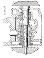
- the construction of the turbocharger centre housing 24 and of the hydraulic turbine 56 is shown in detail in Figures 2 to 8.
- the bearings 26 supporting the shaft 28 comprise, as shown in Figure 2, a thrust bearing assembly 74, and a pair of sleeve-type journal bearings 126.
- the journal bearings 126 are supplied with lubricating oil through an oil inlet port 76 which is coupled to the bearing supply conduit 50 (not shown in Figure 2).
- the oil supplied to the port 76 is led to the bearings via the internal supply passage network, which is shown at 52, and via holes 53 formed in the bearing sleeves 126. From there, the oil drains gravitationally through openings 75 to the bearing oil return line 54 (not shown in ⁇ ⁇ igure 2) via a sump 78.
- the hydraulic turbine 56 is carried on the shaft 28 within a flow chamber 80. More specifically, the hydraulic turbine 56 is positioned against a shoulder 82 on the shaft 28, and is held in place by a sleeve 84 which is in turn retained in position by a thrust collar of the thrust bearing assembly 74. This sleeve 84 forms the journal of the left-hand journal bearing 126.
- the high pressure oil is directed to impinge on the hydraulic turbine 56 by nozzles formed in a generally cylindrical nozzle body 86; a tubular leftwards extension of the nozzle body 86 also forms the housing for the left-hand journal bearing 126.
- This tubular extension includes holes 88 to permit the flow of lubricating oil to the bearing 126, and a drain opening 77 registering with the adjacent bearing drain opening 75.
- the nozzle body 86 has a two-part construction, consisting of an inner portion 89 and an outer portion 90.
- the inner portion 89 is fixed in position in the centre housing 24 by a set screw 87, and, in this example, is fixed to the outer portion 90 by brazing, to define, between the inner and outer portions, a generally semi-annular chamber 92 (see Figure 4).
- the chamber 92 communicates via a plurality of flow openings 91 in the outer portion 90 with a high pressure oil inlet port 94 coupled to the high pressure supply conduit 64 (not shown in Figure 2) for receiving high pressure oil.
- the high pressure oil supplied to the chamber 92 flows out of the chamber 92 via a plurality of nozzles 96 arranged in a semi-circle.
- these nozzles 96 are all skewed with respect to the axis of the shaft 28, so that the oil discharged from the nozzles impinges on the hydraulic turbine 56 with a circumferential component of velocity.
- the nozzles 96 are angled at about 75° to the axis of the shaft 28.
- the hydraulic turbine 56 comprises a central disc 98, and a plurality of blades 100 extending radially outwardly from the disc 98. These blades 100, as shown in Figures 3, 6, and 8, have a generally U-shaped configuration, and are so arranged that the angled oil jets from the nozzles 96 impinge on the concave side of the blades 100.
- a circumferential shroud 102 is formed integrally about the radially outer ends of the blades 100, to improve the effect of the oil jets in driving the blades 100.
- the air in the flow chamber 80 is forced by the incoming flooding oil outwardly from the chamber 80 in both directions along the shaft 28. That is, the air is forced between the sleeve 84 and the nozzle body 86 for escape through the drain openings 75 and 77, and in the other direction past a divider ring 106 secured in position by retaining rings 107,for escape through the other drain opening 75.
- some oil may leak from the flow chamber 80 in both directions along the shaft 28.
- the sleeve 84 includes a slinger 73 aligned with the drain openings 75 and 77 for radially pumping any such leaking oil through the openings 75 and 77 to the sump 78.
- a slinger contour 71 is formed on the shaft 28, between the divider ring 106 and the right-hand bearing sleeve 126, and pumps any leaking oil through the adjacent drain opening 75 to the sump 78. Both the slinger 73 and the slinger contour 71 are positioned inboard of the journal bearings 126, so as to guard against flooding of these bearings.
- the turbocharger journal bearings 126 and the thrust bearing assembly 74 are lubricated solely by the oil supplied via the passage network 52. Seal rings 108 are positioned at opposite ends of the shaft 28 to prevent any of this oil from leaking into either the turbine housing 20 or the compressor housing 22.
- FIG. 9 A second embodiment of the invention is illustrated schematically in Figure 9, in which components identical to those shown in Figures 1 to 8 are designated by the same reference numerals.
- a modified control valve 162 has a position in which it couples the high pressure oil from the high pressure pump 58 through a conduit 109 to a hydraulic motor 110 coupled to drive a fan 112.
- the high pressure oil thus causes the fan 112 to force large quantities of cooling ambient air across cooling surface areas of a charge air cooler heat exchanger 136, before returning to the bearing supply line 50 via a return conduit 113.
- the cooling capacity of the charge air heat exchanger 136 is better than the cooling capacity of the heat exchanger 36 of Figure 1, so that the temperature level of the charge air supplied to the engine 14 is further reduced.
- control valve 162 operates to supply the high pressure oil to the turbocharger 12 under some engine operating conditions for driving the hydraulic turbine 56, and to the hydraulic motor 110 for driving the charge air cooling fan 112 under other engine operating conditions.
- the valve 162 may still, if required, have a position in which it bypasses the high pressure oil to the bearing supply conduit 50 through the line 66, so that the pump 58 can be unloaded during some conditions of engine operation.
- the invention is applicable to both four- stroke internal combustion engines, and two-stroke internal combustion engines.
- the control scheme for the control valves 62 and 162 may be so designed that the conventional scavenging blower may be eliminated.
- the nozzle body 86 shown particularly in Figures 2 to 7 may be modified to include nozzles 96 occupying a full circle. These nozzles 96 may be divided into groups for association with two or more chambers 92 which may in turn be coupled to separately controlled high pressure fluid supply conduits.
Landscapes
- Engineering & Computer Science (AREA)
- Chemical & Material Sciences (AREA)
- Combustion & Propulsion (AREA)
- Mechanical Engineering (AREA)
- General Engineering & Computer Science (AREA)
- Supercharger (AREA)
Applications Claiming Priority (2)
| Application Number | Priority Date | Filing Date | Title |
|---|---|---|---|
| US06/057,790 US4285200A (en) | 1979-07-16 | 1979-07-16 | Hydraulic assist turbocharger system |
| US57790 | 1979-07-16 |
Publications (3)
| Publication Number | Publication Date |
|---|---|
| EP0022678A1 true EP0022678A1 (fr) | 1981-01-21 |
| EP0022678B1 EP0022678B1 (fr) | 1982-09-01 |
| EP0022678B2 EP0022678B2 (fr) | 1987-10-07 |
Family
ID=22012784
Family Applications (1)
| Application Number | Title | Priority Date | Filing Date |
|---|---|---|---|
| EP80302380A Expired EP0022678B2 (fr) | 1979-07-16 | 1980-07-15 | Pompe d'alimentation entrainée par une turbine à gaz d'échappement et par un moyen auxiliaire et moteur à combustion interne avec telle pompe |
Country Status (6)
| Country | Link |
|---|---|
| US (1) | US4285200A (fr) |
| EP (1) | EP0022678B2 (fr) |
| JP (1) | JPS5951649B2 (fr) |
| BR (1) | BR8003382A (fr) |
| CA (1) | CA1143169A (fr) |
| DE (1) | DE3060807D1 (fr) |
Cited By (7)
| Publication number | Priority date | Publication date | Assignee | Title |
|---|---|---|---|---|
| EP0040910A3 (en) * | 1980-05-27 | 1981-12-09 | The Garrett Corporation | Hydraulic assist turbocharger system |
| EP0084433A1 (fr) * | 1982-01-18 | 1983-07-27 | The Garrett Corporation | Arrangement de contrôle pour un turbocompresseur assisté hydrauliquement |
| FR2525276A1 (fr) * | 1982-04-15 | 1983-10-21 | Citroen Sa | Turbocompresseur de suralimentation |
| GB2127897A (en) * | 1982-09-08 | 1984-04-18 | Ricardo Carricarte Grunig | Hydraulic drive charging compressor for internal combustion engines |
| EP0174867A3 (en) * | 1984-09-14 | 1988-02-24 | The Garrett Corporation | Hydraulic assist turbocharger system and method for its operation |
| EP0659983A1 (fr) * | 1993-12-16 | 1995-06-28 | Ford Motor Company Limited | Système hydraulique pour moteurs à combustion interne |
| GB2531606A (en) * | 2014-10-24 | 2016-04-27 | Turbo Dynamics Ltd | Variable speed forced induction with energy recovery and drive control |
Families Citing this family (36)
| Publication number | Priority date | Publication date | Assignee | Title |
|---|---|---|---|---|
| US4478043A (en) * | 1982-01-18 | 1984-10-23 | The Garrett Corporation | Method for controlling the operation of an hydraulic assist turbocharger |
| DE3519650A1 (de) * | 1985-06-01 | 1986-12-04 | Klöckner-Humboldt-Deutz AG, 5000 Köln | Antriebseinheit fuer ein kuehlgeblaese einer brennkraftmaschine |
| US4969332A (en) * | 1989-01-27 | 1990-11-13 | Allied-Signal, Inc. | Controller for a three-wheel turbocharger |
| US4996844A (en) * | 1989-08-15 | 1991-03-05 | Allied-Signal, Inc. | Control system for a three-wheel turbocharger |
| US5113658A (en) * | 1990-05-21 | 1992-05-19 | Allied-Signal, Inc. | Hydraulic assist turbocharger system |
| US5421310A (en) * | 1990-12-24 | 1995-06-06 | Kapich; Davorin | Hydraulic supercharging system |
| US5218822A (en) * | 1992-01-15 | 1993-06-15 | Cooper Industries, Inc. | Air start/assist for turbochargers |
| US5540203A (en) * | 1994-10-05 | 1996-07-30 | Ford Motor Company | Integrated hydraulic system for automotive vehicle |
| US6354268B1 (en) | 1997-12-16 | 2002-03-12 | Servojet Products International | Cylinder pressure based optimization control for compression ignition engines |
| US6273076B1 (en) | 1997-12-16 | 2001-08-14 | Servojet Products International | Optimized lambda and compression temperature control for compression ignition engines |
| US5924286A (en) * | 1998-01-05 | 1999-07-20 | Kapich; Davorin D. | Hydraulic supercharger system |
| DE69911064T2 (de) * | 1999-01-21 | 2004-06-17 | Caterpillar Inc., Peoria | Maschine mit fluidteilsystem |
| US6234270B1 (en) | 1999-01-21 | 2001-05-22 | Caterpillar Inc. | Vehicle having hydraulic and power steering systems using a single high pressure pump |
| US6220521B1 (en) | 1999-01-21 | 2001-04-24 | Caterpillar Inc. | Vehicle hydraulic system that provides heat for passenger compartment |
| US6142110A (en) * | 1999-01-21 | 2000-11-07 | Caterpillar Inc. | Engine having hydraulic and fan drive systems using a single high pressure pump |
| US6412278B1 (en) | 2000-11-10 | 2002-07-02 | Borgwarner, Inc. | Hydraulically powered exhaust gas recirculation system |
| KR20030071666A (ko) * | 2003-07-16 | 2003-09-06 | 백정호 | 자동차 엔진의 과급장치 |
| US20090044788A1 (en) * | 2007-08-17 | 2009-02-19 | Borgwarner Inc. | Engine air boost system |
| DE102009029735A1 (de) | 2009-06-22 | 2010-12-23 | Volkswagen Ag | Brennkraftmaschine mit Abgasturbolader |
| BR112012013742A2 (pt) | 2009-12-08 | 2018-04-03 | Hydracharge Llc | aparelho acelerador de turbo hidráulico |
| US8621865B2 (en) * | 2010-05-04 | 2014-01-07 | Ford Global Technologies, Llc | Internal combustion engine with liquid-cooled turbine |
| US10082070B2 (en) | 2010-12-08 | 2018-09-25 | Hydracharge Llc | High performance turbo-hydraulic compressor |
| US20120180482A1 (en) * | 2011-01-19 | 2012-07-19 | Davorin Kapich | Hydraulic turbine-pump hybrid turbocharger system |
| US20120180480A1 (en) * | 2011-01-19 | 2012-07-19 | Davorin Kapich | Hybrid turbocharger system with brake energy revovery |
| US20120180481A1 (en) * | 2011-01-19 | 2012-07-19 | Davorin Kapich | Hybrid turbocharger system with brake energy revovery |
| US8915082B2 (en) | 2011-02-03 | 2014-12-23 | Ford Global Technologies, Llc | Regenerative assisted turbocharger system |
| US9840972B2 (en) | 2011-05-25 | 2017-12-12 | Eaton Corporation | Supercharger-based twin charging system for an engine |
| US8991176B2 (en) | 2012-03-28 | 2015-03-31 | GM Global Technology Operations LLC | Fluid drive mechanism for turbocharger |
| US20130263619A1 (en) * | 2012-04-09 | 2013-10-10 | Davorin Kapich | Combustion engine waste heat powered air-conditioning system |
| US11591952B2 (en) | 2012-05-21 | 2023-02-28 | Hydracharge Llc | High performance turbo-hydraulic compressor |
| US20140251267A1 (en) * | 2013-03-07 | 2014-09-11 | Ford Global Technologies, Llc | Method and system for improving engine starting |
| GB2551509B (en) * | 2016-06-20 | 2020-08-26 | Ford Global Tech Llc | An engine assembly comprising a camshaft driven oil pump |
| US11255248B2 (en) | 2017-08-15 | 2022-02-22 | Arctic Cat Inc. | Snowmobile having a parallel-path exhaust system for two-stroke engine |
| US11255231B2 (en) | 2017-08-15 | 2022-02-22 | Arctic Cat, Inc. | Pressurized oil system powered by two-stroke engine |
| GB2587362A (en) | 2019-09-24 | 2021-03-31 | Ford Global Tech Llc | Turbocharger |
| US12209599B1 (en) | 2023-03-22 | 2025-01-28 | Savant Holdings LLC | Multi-stage actuator for a turbocharger |
Citations (14)
| Publication number | Priority date | Publication date | Assignee | Title |
|---|---|---|---|---|
| GB488396A (en) * | 1936-08-11 | 1938-07-06 | Maschf Augsburg Nuernberg Ag | Improvements in means for supplying the charge to internal combustion engines |
| US2368033A (en) * | 1943-01-14 | 1945-01-23 | Makaroff Gregory | Hydraulic motor |
| US2417224A (en) * | 1944-01-06 | 1947-03-11 | Weatherhead Co | Differential turbine for fluid transmission |
| GB632615A (en) * | 1946-11-02 | 1949-11-28 | Goetaverken Ab | Improvements in or relating to the supply of scavenging air to internal combustion engines |
| US2968914A (en) * | 1955-07-06 | 1961-01-24 | Laval Steam Turbine Co | Turbocharging of internal combustion engines |
| FR1404460A (fr) * | 1964-03-11 | 1965-07-02 | Turbine fonctionnant avec tout liquide ainsi qu'à air comprimé | |
| GB1095898A (en) * | 1965-07-06 | 1967-12-20 | Cav Ltd | Turbo-chargers |
| US3389554A (en) * | 1966-09-09 | 1968-06-25 | Sulzer Ag | Supercharged internal combustion piston engine |
| US3473322A (en) * | 1966-09-09 | 1969-10-21 | Sulzer Ag | Supercharged internal combustion piston engine |
| DE1751941A1 (de) * | 1968-08-22 | 1970-09-17 | Kickbusch Dipl Ing Ernst | Verbrennungskraftmaschine mit Aufladung durch Abgasturbine und Verdraengerlader |
| DE1935230A1 (de) * | 1969-07-11 | 1971-01-14 | Kickbusch Dipl Ing Ernst | Verbrennungsmotor mit Aufladung durch Abgasturbine und Verdraengerlader |
| US3869866A (en) * | 1972-03-30 | 1975-03-11 | Tectonics Research Ireland Lim | Internal combustion engine turbocharger drives and controls |
| US3921403A (en) * | 1974-04-30 | 1975-11-25 | Garrett Corp | Auxiliary air supply system and method for turbocharged engines |
| US4083188A (en) * | 1977-02-10 | 1978-04-11 | The Garrett Corporation | Engine turbocharger system |
Family Cites Families (2)
| Publication number | Priority date | Publication date | Assignee | Title |
|---|---|---|---|---|
| US3099385A (en) * | 1960-03-07 | 1963-07-30 | Napier & Son Ltd | Turbo blowers |
| US3927530A (en) * | 1974-05-28 | 1975-12-23 | Anton Braun | Supercharged internal combustion engine |
-
1979
- 1979-07-16 US US06/057,790 patent/US4285200A/en not_active Expired - Lifetime
-
1980
- 1980-04-14 CA CA000349774A patent/CA1143169A/fr not_active Expired
- 1980-05-29 BR BR8003382A patent/BR8003382A/pt unknown
- 1980-07-10 JP JP55093378A patent/JPS5951649B2/ja not_active Expired
- 1980-07-15 EP EP80302380A patent/EP0022678B2/fr not_active Expired
- 1980-07-15 DE DE8080302380T patent/DE3060807D1/de not_active Expired
Patent Citations (14)
| Publication number | Priority date | Publication date | Assignee | Title |
|---|---|---|---|---|
| GB488396A (en) * | 1936-08-11 | 1938-07-06 | Maschf Augsburg Nuernberg Ag | Improvements in means for supplying the charge to internal combustion engines |
| US2368033A (en) * | 1943-01-14 | 1945-01-23 | Makaroff Gregory | Hydraulic motor |
| US2417224A (en) * | 1944-01-06 | 1947-03-11 | Weatherhead Co | Differential turbine for fluid transmission |
| GB632615A (en) * | 1946-11-02 | 1949-11-28 | Goetaverken Ab | Improvements in or relating to the supply of scavenging air to internal combustion engines |
| US2968914A (en) * | 1955-07-06 | 1961-01-24 | Laval Steam Turbine Co | Turbocharging of internal combustion engines |
| FR1404460A (fr) * | 1964-03-11 | 1965-07-02 | Turbine fonctionnant avec tout liquide ainsi qu'à air comprimé | |
| GB1095898A (en) * | 1965-07-06 | 1967-12-20 | Cav Ltd | Turbo-chargers |
| US3389554A (en) * | 1966-09-09 | 1968-06-25 | Sulzer Ag | Supercharged internal combustion piston engine |
| US3473322A (en) * | 1966-09-09 | 1969-10-21 | Sulzer Ag | Supercharged internal combustion piston engine |
| DE1751941A1 (de) * | 1968-08-22 | 1970-09-17 | Kickbusch Dipl Ing Ernst | Verbrennungskraftmaschine mit Aufladung durch Abgasturbine und Verdraengerlader |
| DE1935230A1 (de) * | 1969-07-11 | 1971-01-14 | Kickbusch Dipl Ing Ernst | Verbrennungsmotor mit Aufladung durch Abgasturbine und Verdraengerlader |
| US3869866A (en) * | 1972-03-30 | 1975-03-11 | Tectonics Research Ireland Lim | Internal combustion engine turbocharger drives and controls |
| US3921403A (en) * | 1974-04-30 | 1975-11-25 | Garrett Corp | Auxiliary air supply system and method for turbocharged engines |
| US4083188A (en) * | 1977-02-10 | 1978-04-11 | The Garrett Corporation | Engine turbocharger system |
Cited By (8)
| Publication number | Priority date | Publication date | Assignee | Title |
|---|---|---|---|---|
| EP0040910A3 (en) * | 1980-05-27 | 1981-12-09 | The Garrett Corporation | Hydraulic assist turbocharger system |
| EP0084433A1 (fr) * | 1982-01-18 | 1983-07-27 | The Garrett Corporation | Arrangement de contrôle pour un turbocompresseur assisté hydrauliquement |
| FR2525276A1 (fr) * | 1982-04-15 | 1983-10-21 | Citroen Sa | Turbocompresseur de suralimentation |
| EP0092467A1 (fr) * | 1982-04-15 | 1983-10-26 | Automobiles Citroen | Turbo compresseur de suralimentation |
| GB2127897A (en) * | 1982-09-08 | 1984-04-18 | Ricardo Carricarte Grunig | Hydraulic drive charging compressor for internal combustion engines |
| EP0174867A3 (en) * | 1984-09-14 | 1988-02-24 | The Garrett Corporation | Hydraulic assist turbocharger system and method for its operation |
| EP0659983A1 (fr) * | 1993-12-16 | 1995-06-28 | Ford Motor Company Limited | Système hydraulique pour moteurs à combustion interne |
| GB2531606A (en) * | 2014-10-24 | 2016-04-27 | Turbo Dynamics Ltd | Variable speed forced induction with energy recovery and drive control |
Also Published As
| Publication number | Publication date |
|---|---|
| JPS5951649B2 (ja) | 1984-12-15 |
| JPS5618025A (en) | 1981-02-20 |
| CA1143169A (fr) | 1983-03-22 |
| EP0022678B1 (fr) | 1982-09-01 |
| US4285200A (en) | 1981-08-25 |
| BR8003382A (pt) | 1981-03-31 |
| EP0022678B2 (fr) | 1987-10-07 |
| DE3060807D1 (en) | 1982-10-28 |
Similar Documents
| Publication | Publication Date | Title |
|---|---|---|
| EP0022678B1 (fr) | Pompe d'alimentation entrainée par une turbine à gaz d'échappement et par un moyen auxiliaire et moteur à combustion interne avec telle pompe | |
| EP0040910B1 (fr) | Système de suralimentation avec un turbocompresseur à commande hydraulique auxiliaire | |
| CA1134417A (fr) | Porte-palier a joint lubrifiant incorpore | |
| EP0420786B1 (fr) | Piston d'allègement et arrangement de garniture | |
| US3844110A (en) | Gas turbine engine internal lubricant sump venting and pressurization system | |
| US5509381A (en) | Method of and means for cooling and lubricating an alternator | |
| US5145334A (en) | Turbocharger bearing retention and lubrication system | |
| US4268229A (en) | Turbocharger shaft seal arrangement | |
| US4722666A (en) | Nose cowl mounted oil lubricating and cooling system | |
| US11549395B2 (en) | Foil-air bearing assembly for engine starter | |
| EP3786459B1 (fr) | Compresseur centrifuge et turbocompresseur comportant ledit compresseur centrifuge | |
| RU98107145A (ru) | Топливный насос | |
| EP1471223B1 (fr) | Pompe à eau pour moteur diesel avec palier préchargé | |
| US4703726A (en) | Lubricating system for engine | |
| US4205525A (en) | Turbine engine lubrication system | |
| JPS6040731A (ja) | 過給式エンジンの過給機潤滑装置 | |
| JPH07208191A (ja) | ターボチャージャー | |
| US4826410A (en) | Cooling systems for rotary piston engines | |
| CA1156841A (fr) | Turbocompresseur | |
| US3832980A (en) | Combined hydraulic speed-change, cooling and lubricating system in rotary engine | |
| JPS5970830A (ja) | タ−ボ過給機 | |
| US3528398A (en) | Lubricating system for rotary piston internal combustion engines | |
| JPS595833A (ja) | 過給機 | |
| US12385435B1 (en) | Bearing scavenge pump incorporated into turbine disk cover plate | |
| JPS5965518A (ja) | タ−ボ過給機 |
Legal Events
| Date | Code | Title | Description |
|---|---|---|---|
| PUAI | Public reference made under article 153(3) epc to a published international application that has entered the european phase |
Free format text: ORIGINAL CODE: 0009012 |
|
| AK | Designated contracting states |
Designated state(s): DE FR GB IT SE |
|
| 17P | Request for examination filed |
Effective date: 19810203 |
|
| ITF | It: translation for a ep patent filed | ||
| GRAA | (expected) grant |
Free format text: ORIGINAL CODE: 0009210 |
|
| AK | Designated contracting states |
Designated state(s): DE FR GB IT SE |
|
| REF | Corresponds to: |
Ref document number: 3060807 Country of ref document: DE Date of ref document: 19821028 |
|
| PLBI | Opposition filed |
Free format text: ORIGINAL CODE: 0009260 |
|
| 26 | Opposition filed |
Opponent name: M.A.N. MASCHINENFABRIK AUGSBURG-NUERNBERG AKTIENGE Effective date: 19830212 |
|
| PUAH | Patent maintained in amended form |
Free format text: ORIGINAL CODE: 0009272 |
|
| STAA | Information on the status of an ep patent application or granted ep patent |
Free format text: STATUS: PATENT MAINTAINED AS AMENDED |
|
| ITF | It: translation for a ep patent filed | ||
| 27A | Patent maintained in amended form |
Effective date: 19871007 |
|
| AK | Designated contracting states |
Kind code of ref document: B2 Designated state(s): DE FR GB IT SE |
|
| ET3 | Fr: translation filed ** decision concerning opposition | ||
| ITTA | It: last paid annual fee | ||
| PGFP | Annual fee paid to national office [announced via postgrant information from national office to epo] |
Ref country code: SE Payment date: 19920713 Year of fee payment: 13 |
|
| PG25 | Lapsed in a contracting state [announced via postgrant information from national office to epo] |
Ref country code: SE Effective date: 19930716 |
|
| EUG | Se: european patent has lapsed |
Ref document number: 80302380.3 Effective date: 19940210 |
|
| PGFP | Annual fee paid to national office [announced via postgrant information from national office to epo] |
Ref country code: GB Payment date: 19970620 Year of fee payment: 18 |
|
| PGFP | Annual fee paid to national office [announced via postgrant information from national office to epo] |
Ref country code: FR Payment date: 19970711 Year of fee payment: 18 |
|
| PGFP | Annual fee paid to national office [announced via postgrant information from national office to epo] |
Ref country code: DE Payment date: 19970729 Year of fee payment: 18 |
|
| PG25 | Lapsed in a contracting state [announced via postgrant information from national office to epo] |
Ref country code: GB Free format text: LAPSE BECAUSE OF NON-PAYMENT OF DUE FEES Effective date: 19980715 |
|
| GBPC | Gb: european patent ceased through non-payment of renewal fee |
Effective date: 19980715 |
|
| PG25 | Lapsed in a contracting state [announced via postgrant information from national office to epo] |
Ref country code: FR Free format text: LAPSE BECAUSE OF NON-PAYMENT OF DUE FEES Effective date: 19990331 |
|
| PG25 | Lapsed in a contracting state [announced via postgrant information from national office to epo] |
Ref country code: DE Free format text: LAPSE BECAUSE OF NON-PAYMENT OF DUE FEES Effective date: 19990501 |
|
| REG | Reference to a national code |
Ref country code: FR Ref legal event code: ST |