EP0023181A1 - Automatisches Registriergerät für die Gebühren einer telephonischen Verbindung und zugehörige Telephonzentrale - Google Patents
Automatisches Registriergerät für die Gebühren einer telephonischen Verbindung und zugehörige Telephonzentrale Download PDFInfo
- Publication number
- EP0023181A1 EP0023181A1 EP19800401079 EP80401079A EP0023181A1 EP 0023181 A1 EP0023181 A1 EP 0023181A1 EP 19800401079 EP19800401079 EP 19800401079 EP 80401079 A EP80401079 A EP 80401079A EP 0023181 A1 EP0023181 A1 EP 0023181A1
- Authority
- EP
- European Patent Office
- Prior art keywords
- tax
- communication
- cost
- pulses
- period
- Prior art date
- Legal status (The legal status is an assumption and is not a legal conclusion. Google has not performed a legal analysis and makes no representation as to the accuracy of the status listed.)
- Granted
Links
- 230000008878 coupling Effects 0.000 claims abstract description 7
- 238000010168 coupling process Methods 0.000 claims abstract description 7
- 238000005859 coupling reaction Methods 0.000 claims abstract description 7
- 230000004044 response Effects 0.000 claims abstract description 6
- 238000004891 communication Methods 0.000 claims description 88
- 230000006854 communication Effects 0.000 claims description 88
- 238000001514 detection method Methods 0.000 claims description 20
- 230000005540 biological transmission Effects 0.000 claims description 14
- 230000001186 cumulative effect Effects 0.000 claims description 8
- 230000005764 inhibitory process Effects 0.000 claims 1
- 238000012545 processing Methods 0.000 description 14
- 238000010586 diagram Methods 0.000 description 6
- 230000006870 function Effects 0.000 description 4
- 238000004364 calculation method Methods 0.000 description 3
- 230000011664 signaling Effects 0.000 description 3
- 235000021183 entrée Nutrition 0.000 description 2
- 239000004973 liquid crystal related substance Substances 0.000 description 2
- 210000000056 organ Anatomy 0.000 description 2
- 238000010200 validation analysis Methods 0.000 description 2
- 230000035508 accumulation Effects 0.000 description 1
- 238000009825 accumulation Methods 0.000 description 1
- 239000013078 crystal Substances 0.000 description 1
- 238000006073 displacement reaction Methods 0.000 description 1
- 230000001939 inductive effect Effects 0.000 description 1
- 239000003550 marker Substances 0.000 description 1
- 238000012986 modification Methods 0.000 description 1
- 230000004048 modification Effects 0.000 description 1
- 230000002093 peripheral effect Effects 0.000 description 1
- 239000010453 quartz Substances 0.000 description 1
- 238000011160 research Methods 0.000 description 1
- VYPSYNLAJGMNEJ-UHFFFAOYSA-N silicon dioxide Inorganic materials O=[Si]=O VYPSYNLAJGMNEJ-UHFFFAOYSA-N 0.000 description 1
- 230000029305 taxis Effects 0.000 description 1
- 230000002123 temporal effect Effects 0.000 description 1
- 238000012800 visualization Methods 0.000 description 1
- 238000004804 winding Methods 0.000 description 1
Images


Classifications
-
- H—ELECTRICITY
- H04—ELECTRIC COMMUNICATION TECHNIQUE
- H04M—TELEPHONIC COMMUNICATION
- H04M15/00—Arrangements for metering, time-control or time indication ; Metering, charging or billing arrangements for voice wireline or wireless communications, e.g. VoIP
- H04M15/28—Arrangements for metering, time-control or time indication ; Metering, charging or billing arrangements for voice wireline or wireless communications, e.g. VoIP with meter at substation or with calculation of charges at terminal
- H04M15/30—Arrangements for metering, time-control or time indication ; Metering, charging or billing arrangements for voice wireline or wireless communications, e.g. VoIP with meter at substation or with calculation of charges at terminal the meter or calculation of charges not being controlled from an exchange
Definitions
- the present invention relates to an apparatus for recording the cost of a telephone communication
- the display means of certain variants indicate to the subscriber, in addition to certain data relating to the call such as the call number of the subscriber requested, the time of establishment of the call and the duration of the call, also charging data.
- These charging data are mainly the number of charging pulses detected by the recording device (French patent application 2,340,001, German patent application DT-OS 25 58,680), the cost of communication (French patent application 2,427,016, US patent 4,146,746, German patent applications DT-OS 25 05 728, DT-AS 22 48 468, DT-OS 27 09 461 and DT-OS 23 36 102) and, optionally, the number of cumulative tax pulses (German patent application DT-OS 25 18 063) as well as the total cumulative cost which relate to communications established during a predetermined period (French patent application 2,427,016).
- the cost setting means may include an addition loop which includes a summator which adds the current cost of the current call stored in a random access memory to the basic charge, in response to the detection of a charge pulse.
- the cost setting means can comprise a down counter which counts a number of pulses this said clock equal to the number of monetary units representing the basic tax, in response to the detection of a tax pulse, and which transmits said number of clock pulses to a current cost counter.
- the current cost counter records the increasing cost of the call in progress which can be displayed, either during or at the end of the call after hanging up on the calling subscriber, under the control of timing means (patent application French 2,427,016, American patent 4,176,746, German patent application DT-OS 25 05 728).
- such recording devices include, as first storage means, a register, such as coding wheels or a set of switches, the content of which is selected manually by the subscriber. to register the basic call charge.
- this basic charge depends on the type of call requested, that is to say on the home area of the requested subscriber. Consequently, before the subscriber picks up the handset of his extension, he must look in the taxation table given by the administration for the cost of the basic charge for the call to be established, according to the prefix of the call number. requested, then display in said first storage means this basic charge.
- the object of the present invention is to provide a recording device which, together with certain modifications to its central office, allows the automatic calculation of the cost of a communication without requiring the transmission of tax pulses over the telephone line from the central to the subscriber station.
- the recording device itself generates the tax pulses as soon as a communication is established, unlike all known recording devices. This generation of pulses is automatic, without manual intervention by the subscriber.
- a recording device of the type defined in the introduction, is characterized in that it comprises means connected to the coupling means for detecting a coded message of data, such as the period tax pulses relating to said communication, which is transmitted by the central office of the said station after the numbering of the requested call number, of the second means for memorizing the period of the tax pulses and of the means connected to the second storage means and to said clock for producing pulses charge to said charge period counted by said charge counter in response to the detected message.
- a coded message of data such as the period tax pulses relating to said communication
- the messages exchanged between the home office and the recording device are produced using modems.
- the central office of the subscriber comprises means interconnected between the trunk of the subscriber line and the payer of said central office for coding and transmitting coded messages of data to said device on the order of said taxmaster.
- the message essentially comprises a word indicating the type of charging for the call, that is to say whether it is charged on the basis of duration or not, as well as the basic charge and the period of the impulse charges, known as the level of tax (PT).
- the basic charge can be displayed automatically at the start of the call and avoids any tedious research on the part of the subscriber.
- the aforementioned message and other messages prepared by the central office or the recording device are transmitted during the call establishment phase or outside the conversation phase. No signaling transmission, such as charge pulses according to the prior art, thus 'pollutes' the telephone line during the conversation., Since the payer and the associated modulator are assigned to a plurality of subscriber telephone lines, by simple automatic switching, the cost of the central supervision unit is reduced.
- the clock contained in the recording device is of high stability and serves as a reference in order to produce tax pulses.
- the recording device can include a programmable frequency divider receiving the clock pulses and means connected to said second storage means for selecting outputs of the programmable frequency divider according to the stored tax period so that said divider periodically counts a number of clock pulses equal to the ratio of the tax period and the period of the clock pulses and transmits to the tax counter tax pulses at said tax period.
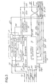
- a recording device fulfilling the main functions, such as developing and viewing the cost of a communication.
- the recording device essentially comprises a detection circuit 1 for detecting certain supervision signals emitted during the establishment of a telephone call and a data message relating to the charging of the call, a control unit 2 developing according to a program pre-recorded all the orders for the calculation of the cost of the communication, and a counting and display circuit 3 which is controlled by the control unit in order to calculate and display the cost of the communication.
- the detection circuit 1 comprises a demodulator 10 in series with a decoder 11, and a detector 12.
- the detector 12 detects supervision signals such as the polarity reversals of the central office battery telephone 4 to which the subscriber telephone set 5 is attached through the telephone line TR.
- Demodulator 10 and other planned modulators and demodulators for the present invention are of the bivalent series modulation type obtained by frequency displacement. They comply, for example, with the prescriptions of opinion V 21 of the International Circuit and Telephone Consultative Committee (C. C. I. TT). They are mainly characterized by a low modulation speed of the order of 200 bauds and by two so-called return channels, respectively at average nominal frequencies respectively equal to 1080 Hz and 1750 Hz with a frequency excursion of ⁇ 100 Hz. The highest characteristic frequency on each channel corresponds to an "O" bit.
- the demodulator 10 receives a charging message.
- the bits in state "1" correspond to the lowest characteristic frequency of the return channel equal to 1650 Hz and the bits in state "0" correspond to the highest characteristic frequency equal to 1850 Hz
- the demodulator 10 is of the known FSK type, that is to say operates by frequency sliding by means of a phase locked loop through a voltage controlled oscillator.
- the demodulator 10 is connected in a known manner to the subscriber telephone line TR at the level of the station 5, via a coupler.
- This coupler can be of the type comprising a differential transformer, photo-couplers, diode bridges or relays and contacts, or alternatively, of the inductive coupler type whose winding cooperates with the coil of the audio circuit of the telephone set.
- a telcoupler is shown diagrammatically at 6 in FIGS. 1 and 2, and reference will be made to the patent applications and patents already cited in the introduction with regard to the characteristics of these different couplers.
- the detection circuit 1 comprises a supervision signal detector 12. It optionally comprises, in a manner analogous to that described for example in French patent 2,270,738, first and second flip-flops whose inputs are respectively connected to the photo-couplers of coupler 6.
- the output 120 of the first flip-flop goes from state “0" to state "1 when there is a first reversal of the polarity of the central office battery after off-hook of the called subscriber, initializing the start of the conversation.
- the output 121 of the second flip-flop goes from state "0" to state "1" as soon as a second polarity opposite to the previous one is present after hanging up the handset of station 5.
- the scales of detector 12 will be implemented, preferably, when the home exchange 4 performs such a battery reversal, in which case the aforementioned first coded word may not be transmitted by the exchange, since the detection of the first battery reversal is an indication analogous to that of the first coded word.
- the hanging up can be detected by means of a switch which is closed when the telephone handset is hung up, in a manner analogous to the switching hooks of the telephone station 5.
- the control unit 2 is detailed in FIG. 3. It comprises a central processing unit 20, of the microprocessor type, which interprets and executes instructions according to a program prerecorded in an internal read-only memory which is addressed by the order signals transmitted by the detection circuit. 2.
- the central unit 20 receives by a first input 200, through an OR gate 13, a signal for establishing the conversation, when the decoder. 11 has detected and transmitted on its output 110 said first coded word, or when the detector 12 has detected said first battery reversal and sets the output wire 120 to state "1".
- a second input 201 of the unit 20 receives a second coded word, that is to say the bit indicating the type of charging for the communication, when the decoder 11 has detected and transmitted on its output 111 said second coded word.
- the unit 20 receives by an input 202, which is connected to the output 121 of the supervision signal detector 12, a signal "1" when the detector 12 has detected the hanging up at the end of the communication.
- the control unit 2 also includes a random access memory 21 and an address register 22.
- the random access memory 21 is made up of two cells 210 and 211.
- the cell 210 stores said third coded word indicating the cost of the basic tax TB on writing order transmitted on a wire 203 by the processing unit 20 to one of the inputs of an AND gate 212.
- Said fourth word coded indicating the level of tax PT is memorized in the second cell 211 on writing order transmitted on a wire 204 by the processing unit 20 to one of the inputs of a second AND gate 213.
- the other inputs of the doors AND 212 and 213 receive the words TB and PT from outputs 112 and 113 of the decoder 11.
- the address register 22 receives, through the output wire 21 4 from cell 211, the tax level word PT when this cell is read by the processing unit 20 through a wire 205.
- the bus output 220 of register 22 delivers, in response to each level of tax PT, an output address of a programmable frequency divider 31 of the counting and display circuit 3, as will be seen below with reference to FIG . 4.
- the word for cost of the basic tax TB is also read in cell 210, on the order of unit 20 delivered on a wire 206, and is transmitted on the output wire 215 of cell 210 to an arithmetic unit 33 of circuit 3.
- the counting and display circuit 3 essentially comprises the following circuits.
- a clock 30 produces pulses having determined frequencies.
- the programmable frequency divider 31 generates tax pulses whose frequency is equal to the inverse of the tax level PT and therefore depends on the type of communication requested, i.e. the prefix or prefixes national and international call number of the subscriber requested.
- a charge counter 32 counts the charge impulses during the talk time between the end of the dialing phase and the hang up.
- the arithmetic unit 33 establishes the cost of the communication and a display unit 34 displays charging data such as the cost of the communication CC.
- the clock 30 includes a quartz crystal oscillator of great stability to the output of which is connected a series of suitable frequency dividers in order to produce a reference frequency transmitted on a wire 300 for setting the time base included in the processing unit 20, and a clock frequency transmitted on a wire 301, through an AND gate 302, to the counting input 310 of the programmable divider 31.
- the clock frequency is equal to the greatest common frequency divider of the charge pulses. This clock frequency is equal to 10 Hz, since the basic charge periods for international communications, among others, are currently defined to the nearest 0.1 s.
- This clock 30 as well as all the circuits of the device recording.ur are supplied by a local voltage supply 7, shown in Fig. 1, which includes a battery or rectifier and a transformer connected to the mains in the subscriber's premises.
- the power supply 7 is connected in a known manner to the device through a switch 70 whose closing is, for example, controlled by a relay or a photocoupler suitably inserted in the audio circuit of the telephone set, when the handset of the set is off the hook, and the opening of which is controlled after a predetermined period of time following the hanging up by instruction from the processing unit 20 through a wire 207.
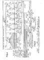
- the programmable frequency divider 31 is composed of four decimal counters 311 d , 311 U , 311 D and 311 C , which are fixed module, that is to say with maximum count limited to ten, and four circuits of access to the outputs of the counters 312 d , 312 U , 312 D and 312.
- the four counters each automatically reset to zero when their count is equal to ten and allow counting up to 9999 clock pulses, at the frequency of 10 Hz.
- They are capable of producing tax pulses between the smallest tax period currently in force, which is equal to 1, 3 s for a communication for example between France and Japan, and the largest tax period which is equal to 240 s for a communication for example established at night between a requesting subscriber in the Paris area and a requested subscriber in the first peripheral Paris area.
- Each counter 311 has ten outputs S to S 9 .
- the counting input C d of the counter 311 d which is assigned to tenths of a second, is connected to the output 301 of the clock 30, through the AND gate 302.
- the other input of the AND gate 302 is connected by wire 208 to the processing unit 20 which opens it as soon as the unit 20 receives on its input 201 the bit "1" of the second coded word indicating that the communication is charged for the duration and until detection of the hanging up on its input 202.
- the counting input C U , C D , C C of each of the three other counters 311 1 U , 311 D , 311, which are assigned respectively to the units, tens and hundreds of second, is connected to the carry-over output SR d , SR U , SR C of the previous counter 311 d , 311 U , 311 D.
- Each SR report output of a counter emits a pulse when the counter count is equal to ten.
- the other inputs of the AND gates 313 of the access circuits 31 2 selectively receive opening control signals by the output bus 220 to 40 wires from the address register 22.
- the outputs of the ten AND gates 313 O to 313 g of each access circuit 312 d , 312 U , 312 D , 312 C are connected to one of the four inputs of an AND gate 315 through an OR gate 314 d , 314 314 D , 314 C.
- the output of the AND gate 315 is connected to the counting input C of the tax counter 32 and, through an OR gate 316, to the reset reset inputs of the four counters 311, 311, 31 1 D and 311.
- the output of gate 315 transmits the tax pulses at the frequency selected (1 / PT) by register 22 each time the outputs of the four OR gates 314 are in the state "1".
- the address register selects, through the bus 220, the outputs S 5 , S 9 , S 0 and S 0 counters 311 d , 311, 3 1 1 D and 311 C by putting in state "1" the inputs of the corresponding AND gates 313 5 , 313 9 , 3130 and 313 O respectively in the access circuits 31 2d, 312 U , 312 D and 312 C.
- the counters 311 are reset simultaneously all the 9, 5 s, that is to say, each emitting a charge pulse transmitted at the 9.5 s period of the output of the AND gate 315 to the 'compta- input e g C Charging meter 32.
- the tax counter 32 counts the tax pulses during the entire talk time, i.e. when the AND gate 302 is open.
- the tax account CT in the counter 32 and the cost of the tax TB base memorized in cell 210 are read and transmitted through wires 320 and 215 to the two inputs of the arithmetic unit 33 on read order transmitted on wire 206 by unit 20.
- the unit 34 includes, for example, a printer and / or a light-emitting diode or liquid crystal display device illustrated at 341 in FIG. 4.
- the display unit 34 is of a known type and receives from the unit 20, through the control bus 209, all the instructions relating to printing (step by step advance of the recording medium, columns by columns, then lines by lines) and / or a display of a number (control of the light-emitting diodes or the bars of liquid crystals assigned to each line) each time a number must be printed or displayed. This number can be preceded by a character indicating the type of data to the subscriber.
- the central unit 20 directly controls the display of the cost of the basic fee TB through doors 212, 216 and 216 'and maintains closed the AND 302 door, so that no counting takes place during the duration of the communication.
- the processing unit 20 transmits an order on the ril 217 reset (reset) which controls the emptying of cells 210 and 211, the resetting of the counters 311, through the OR gate 316, and the resetting of the tax counter 32. Then the unit 20 transmits on the til 207 an order to open the switch 70 so that the recording device does not consume energy when the telephone set is not in use.
- FIG. 5 the main organs of an automatic telephone exchange of the spatial type with regard to the transmission on the subscriber side. These organs are shown diagrammatically in FIG. 5.
- FIG. 5 In general, firstly, only the functions of these bodies participating in the charging of an outgoing call from a subscriber whose station is associated with an art charging recording device will be described. and receives tax pulses from the subscriber line.
- the subscriber line TR is connected, through an input trunk 40, to the connection network 41 which includes the various selection stages in order to connect the local subscriber lines and the transmission routes with others. central.
- the connection network 41 exchanges information to ensure these said connections and various supervision signals with a central supervision block.
- This block comprises, in a known manner, one or more multi-recorders and markers each assigned to predetermined subscriber lines, a translator and a taxer.
- the multi-assignment register 42 receives the dialing pulses and establishes all the supervision signals, such as tone and signaling, necessary for establishing a call.
- the multi-recorder 42 transmits, at the start of a communication, to the taxer 43 the level of tax to be charged, and certain discriminations such as those indicating whether the subscriber is entitled to the tax indication, that is to say at- say whether the subscriber unit is associated with a charge recording device and must receive charge pulses.
- the allocation marker 44 provides the links between the connection network on the one hand and the multirecorders, the taxer, the translator and the central office management unit on the other hand.
- the translator 45 associated with the multi-recorder 42 acts as a memory for the multi-recorder and provides in particular to the latter, at the end of the call, the basic charge to be charged for the call.
- the taxer 43 determines, at the end of the communication, the cost of the communication and transmits it to the management body 46.
- the taxer includes a timer which produces on its different outputs all the tax frequencies currently in force which are selected by the taxer according to the established call.
- the tax pulses are transmitted through the trunk 40 to the subscriber's tax recorder.
- the taxeur 43 instead of controlling the transmission of the tax pulses, transmits, through the trunk 40, by means of a modulator 47 in accordance with the abovementioned opinion V 21 of C. VS . I. T. T., the charging message as defined above.
- the tax pulses not transmitted to the subscriber station in accordance with the invention, no longer need to be counted by the tax payer, if the latter can have access, at the end of the communication, to the CT tax account or, more precisely, to the cost of the CC communication established by the multiplier 33 of the recording device.
- the recording device comprises a modulator 80 and an encoder 81, as shown in FIG. 6.
- the modulator 80 and the demodulator 10 form a modem in accordance with opinion V 21 of C. VS . I. T. T.
- the modulator 80 has its output connected to the telephone line TR through the coupler 6.
- the payer 43 transmits a so-called end of communication message on the telephone line TR.
- This message demodulated by the demodulator 10 and decoded by the decoder 11 of the recording device, indicates through the wire 114 to the central unit 20 (Figs.
- the reading order on wire 206 also controls, through an OR gate 810, the transmission of the CT tax account from output 320 of the tax meter 32 to the input 811 of the decoder 81, then that of the cost CC of the output 330 of the multiplier 33 to the input 811.
- the words CT and CC are received by the payer 43 from the central office through the trunk 40 and a demodulator 48 in accordance with opinion V 21 of the CCITT. This information will be transmitted to the management body 46 of the central office by the payer 43.
- Each of the preceding readings is followed by a reset to the internal memory of the accumulator 35, 36.
- This cumulative account and cost message is transmitted by the modulator 80 to the central 4, including the management unit 46 will establish the billing according to the previous cumulative data.
- an alphanumeric keyboard (not shown) can be provided controlling the central processing unit 20 so that the recording medium of the display unit 34 displays on order of the subscriber the accumulated account and the payment to be invoiced at any desired time during the predetermined period. The subscriber will thus be able to check if errors have been introduced in the billing slip published by the administration.
- the recording device no longer comprises a power switch, such as 70 shown in FIG. 1, so that the device is permanently powered in order to detect, at any time, a message from the home office, as is customary for data terminals.
- any computer at the subscriber's comprising means for producing and counting tax pulses depending on charging data transmitted by the home exchange, belongs to the field of the invention.
- the home telephone exchange can be of the spatial or temporal type without the functions inherent in charging according to the invention being able to be performed in accordance with the description in FIG. 5.
Landscapes
- Engineering & Computer Science (AREA)
- Computer Networks & Wireless Communication (AREA)
- Signal Processing (AREA)
- Meter Arrangements (AREA)
Applications Claiming Priority (2)
| Application Number | Priority Date | Filing Date | Title |
|---|---|---|---|
| FR7919101 | 1979-07-24 | ||
| FR7919101A FR2462071A1 (fr) | 1979-07-24 | 1979-07-24 | Appareil enregistreur automatique du cout d'une communication telephonique |
Publications (2)
| Publication Number | Publication Date |
|---|---|
| EP0023181A1 true EP0023181A1 (de) | 1981-01-28 |
| EP0023181B1 EP0023181B1 (de) | 1982-12-01 |
Family
ID=9228244
Family Applications (1)
| Application Number | Title | Priority Date | Filing Date |
|---|---|---|---|
| EP19800401079 Expired EP0023181B1 (de) | 1979-07-24 | 1980-07-18 | Automatisches Registriergerät für die Gebühren einer telephonischen Verbindung und zugehörige Telephonzentrale |
Country Status (3)
| Country | Link |
|---|---|
| EP (1) | EP0023181B1 (de) |
| DE (1) | DE3061218D1 (de) |
| FR (1) | FR2462071A1 (de) |
Cited By (3)
| Publication number | Priority date | Publication date | Assignee | Title |
|---|---|---|---|---|
| WO1982001634A1 (fr) * | 1980-11-06 | 1982-05-13 | Electr Dev Realisation | Procede et dispositif pour elaborer et delivrer le montant de taxes telephoniques |
| FR2521802A1 (fr) * | 1982-02-15 | 1983-08-19 | Gallo Alain | Calculateur de cout de communications par fil visualisant le cout, la duree, la destination et l'heure locale du pays appele |
| EP0845892A3 (de) * | 1996-12-02 | 1999-12-08 | Nortel Networks Corporation | Abrechnungsverfahren auf Basis einer Bezahlung per Anwendung für Merkmalaktivierung in einem Telefonendgerät |
Citations (5)
| Publication number | Priority date | Publication date | Assignee | Title |
|---|---|---|---|---|
| DE2518063A1 (de) * | 1975-04-23 | 1976-11-04 | Fritscher | Geraet zur anzeige von telefongebuehren |
| DE2558680A1 (de) * | 1975-05-09 | 1976-11-18 | Ind Politecnica Meridionale I | Vorrichtung zur speicherung und zum ausdruck des angerufenen telefonanschlusses und der zahl der gebuehreneinheiten |
| DE2709461A1 (de) * | 1977-03-04 | 1978-09-07 | Standard Elektrik Lorenz Ag | Telefonrechner |
| US4146746A (en) * | 1976-04-30 | 1979-03-27 | Societe Anonyme Francaise Des Appareils Automatiques Safaa | Device for computing and displaying the price of a service |
| GB2028058A (en) * | 1978-08-18 | 1980-02-27 | Keen W D R | Telephone subscriber metering system |
-
1979
- 1979-07-24 FR FR7919101A patent/FR2462071A1/fr active Granted
-
1980
- 1980-07-18 DE DE8080401079T patent/DE3061218D1/de not_active Expired
- 1980-07-18 EP EP19800401079 patent/EP0023181B1/de not_active Expired
Patent Citations (5)
| Publication number | Priority date | Publication date | Assignee | Title |
|---|---|---|---|---|
| DE2518063A1 (de) * | 1975-04-23 | 1976-11-04 | Fritscher | Geraet zur anzeige von telefongebuehren |
| DE2558680A1 (de) * | 1975-05-09 | 1976-11-18 | Ind Politecnica Meridionale I | Vorrichtung zur speicherung und zum ausdruck des angerufenen telefonanschlusses und der zahl der gebuehreneinheiten |
| US4146746A (en) * | 1976-04-30 | 1979-03-27 | Societe Anonyme Francaise Des Appareils Automatiques Safaa | Device for computing and displaying the price of a service |
| DE2709461A1 (de) * | 1977-03-04 | 1978-09-07 | Standard Elektrik Lorenz Ag | Telefonrechner |
| GB2028058A (en) * | 1978-08-18 | 1980-02-27 | Keen W D R | Telephone subscriber metering system |
Non-Patent Citations (1)
| Title |
|---|
| FUNKSCHAU, 1975, Vol. 47, No. 8, Munich DE LAUNER: "Elektronischer Gebuhren-einheiten-Zahler",pages 125-127 * Page 125, colonne de gauche, ligne 1 - colonne de droite, ligne 17 * * |
Cited By (3)
| Publication number | Priority date | Publication date | Assignee | Title |
|---|---|---|---|---|
| WO1982001634A1 (fr) * | 1980-11-06 | 1982-05-13 | Electr Dev Realisation | Procede et dispositif pour elaborer et delivrer le montant de taxes telephoniques |
| FR2521802A1 (fr) * | 1982-02-15 | 1983-08-19 | Gallo Alain | Calculateur de cout de communications par fil visualisant le cout, la duree, la destination et l'heure locale du pays appele |
| EP0845892A3 (de) * | 1996-12-02 | 1999-12-08 | Nortel Networks Corporation | Abrechnungsverfahren auf Basis einer Bezahlung per Anwendung für Merkmalaktivierung in einem Telefonendgerät |
Also Published As
| Publication number | Publication date |
|---|---|
| FR2462071B1 (de) | 1981-12-18 |
| FR2462071A1 (fr) | 1981-02-06 |
| EP0023181B1 (de) | 1982-12-01 |
| DE3061218D1 (en) | 1983-01-05 |
Similar Documents
| Publication | Publication Date | Title |
|---|---|---|
| CA1263197A (fr) | Systeme de communications telephoniques a combines portatifs | |
| EP0115240B1 (de) | Telefonapparat mit Zweirichtungsinfrarotverbindung zwischen Handapparat und mit einer Teilnehmerleitung verbundenem ortsfesten Modul | |
| FR2466151A1 (fr) | Systeme memorisateur et indicateur de numeros de telephone | |
| FR2467523A1 (fr) | Systeme de controle d'un reseau de connexion | |
| FR2611067A1 (fr) | Procedes et dispositifs pour relever a distance des indicateurs numeriques, notamment ceux qui equipent des compteurs | |
| EP0120495B1 (de) | Einrichtung zum Austausch von kodierten Nachrichten zwischen Stationen | |
| EP0023181B1 (de) | Automatisches Registriergerät für die Gebühren einer telephonischen Verbindung und zugehörige Telephonzentrale | |
| EP0188139B1 (de) | Steuerungs- und Überwachungssystem für öffentliche Münzfernsprecher | |
| FR2619234A1 (fr) | Procedes et dispositifs adaptateurs pour introduire des donnees dans des taximetres electroniques a partir d'un ordinateur central relie temporairement a un terminal local | |
| EP0254920B1 (de) | System zum Anschluss von Telefonteilnehmern, rund um eine digitale Zeitmultiplexvermittlungsanlage gestaltet | |
| EP0827359B1 (de) | Billiges, automatisches und transparentes Zugriffverfahren und Protokoll für Telekommunikationsdienste-Anbieter über ISDN | |
| EP0064062A1 (de) | Verfahren und anordnung zum berechnen und abgeben des fernsprechgebührenbetrages | |
| FR2607988A1 (fr) | Perfectionnements aux dispositifs pour delivrer aux abonnes des lignes telephoniques des informations sur leurs communications | |
| FR2606240A1 (fr) | Emetteur-recepteur pour verification de liaisons de transmission et appareil le comportant | |
| EP0018875A1 (de) | Automatische Generatoren für Telephonanrufe | |
| FR2680261A1 (fr) | Carte a memoire et dispositif de taxation telephonique a lecteur de carte. | |
| FR2607646A1 (fr) | Dispositif d'adaptation pour connecter automatiquement un terminal videotex a une ligne telephonique | |
| EP0156693A1 (de) | Schutzeinrichtung gegen elektrische Störungen zwischen einem Terminal und einer Telefonleitung | |
| Meyer | Methods of Transmission of Data at Our Disposition from the French Administration of Telecommunications | |
| FR2805951A1 (fr) | Dispositif de surveillance d'un local comprenant un telephone d'urgence | |
| FR2481551A1 (fr) | Appareil telephonique d'intercommunication a quatre fils, une paire telephonique et une paire de donnees, pour installation d'intercommunication a commande numerique | |
| FR2532805A1 (fr) | Circuit d'affichage de donnees repondant a un paiement | |
| FR2626125A1 (fr) | Systeme de communication telephonique d'appartement a carte | |
| FR2590057A1 (fr) | Systeme de collecte d'informations de dispositifs a surveiller | |
| EP0576364A1 (de) | Universale Fernsprechanrufumleitungseinrichtung |
Legal Events
| Date | Code | Title | Description |
|---|---|---|---|
| PUAI | Public reference made under article 153(3) epc to a published international application that has entered the european phase |
Free format text: ORIGINAL CODE: 0009012 |
|
| AK | Designated contracting states |
Designated state(s): BE CH DE GB IT NL SE |
|
| 17P | Request for examination filed |
Effective date: 19810206 |
|
| ITF | It: translation for a ep patent filed | ||
| GRAA | (expected) grant |
Free format text: ORIGINAL CODE: 0009210 |
|
| AK | Designated contracting states |
Designated state(s): BE CH DE GB IT NL SE |
|
| REF | Corresponds to: |
Ref document number: 3061218 Country of ref document: DE Date of ref document: 19830105 |
|
| PGFP | Annual fee paid to national office [announced via postgrant information from national office to epo] |
Ref country code: DE Payment date: 19840728 Year of fee payment: 5 |
|
| PGFP | Annual fee paid to national office [announced via postgrant information from national office to epo] |
Ref country code: CH Payment date: 19840917 Year of fee payment: 5 |
|
| PGFP | Annual fee paid to national office [announced via postgrant information from national office to epo] |
Ref country code: SE Payment date: 19840930 Year of fee payment: 5 Ref country code: BE Payment date: 19840930 Year of fee payment: 5 |
|
| PGFP | Annual fee paid to national office [announced via postgrant information from national office to epo] |
Ref country code: NL Payment date: 19860731 Year of fee payment: 7 |
|
| PG25 | Lapsed in a contracting state [announced via postgrant information from national office to epo] |
Ref country code: SE Effective date: 19870719 |
|
| PG25 | Lapsed in a contracting state [announced via postgrant information from national office to epo] |
Ref country code: LI Effective date: 19870731 Ref country code: CH Effective date: 19870731 |
|
| BERE | Be: lapsed |
Owner name: BLANC MICHEL Effective date: 19870731 Owner name: GIRARD JEAN Effective date: 19870731 Owner name: SERRES BERNARD Effective date: 19870731 |
|
| PG25 | Lapsed in a contracting state [announced via postgrant information from national office to epo] |
Ref country code: NL Effective date: 19880201 |
|
| NLV4 | Nl: lapsed or anulled due to non-payment of the annual fee | ||
| REG | Reference to a national code |
Ref country code: CH Ref legal event code: PL |
|
| PG25 | Lapsed in a contracting state [announced via postgrant information from national office to epo] |
Ref country code: DE Effective date: 19880401 |
|
| GBPC | Gb: european patent ceased through non-payment of renewal fee | ||
| PG25 | Lapsed in a contracting state [announced via postgrant information from national office to epo] |
Ref country code: GB Free format text: LAPSE BECAUSE OF NON-PAYMENT OF DUE FEES Effective date: 19881118 |
|
| PG25 | Lapsed in a contracting state [announced via postgrant information from national office to epo] |
Ref country code: BE Effective date: 19890731 |
|
| EUG | Se: european patent has lapsed |
Ref document number: 80401079.1 Effective date: 19880831 |
|
| PLBE | No opposition filed within time limit |
Free format text: ORIGINAL CODE: 0009261 |
|
| STAA | Information on the status of an ep patent application or granted ep patent |
Free format text: STATUS: NO OPPOSITION FILED WITHIN TIME LIMIT |