EP0023338A2 - Appareil pour le dosage et le levage des composants pour la préparation du béton - Google Patents
Appareil pour le dosage et le levage des composants pour la préparation du béton Download PDFInfo
- Publication number
- EP0023338A2 EP0023338A2 EP80104294A EP80104294A EP0023338A2 EP 0023338 A2 EP0023338 A2 EP 0023338A2 EP 80104294 A EP80104294 A EP 80104294A EP 80104294 A EP80104294 A EP 80104294A EP 0023338 A2 EP0023338 A2 EP 0023338A2
- Authority
- EP
- European Patent Office
- Prior art keywords
- feeder box
- metering
- frame part
- frame
- box
- Prior art date
- Legal status (The legal status is an assumption and is not a legal conclusion. Google has not performed a legal analysis and makes no representation as to the accuracy of the status listed.)
- Granted
Links
- 239000000654 additive Substances 0.000 title description 5
- 230000003028 elevating effect Effects 0.000 title 1
- 238000004519 manufacturing process Methods 0.000 claims abstract description 3
- 238000013016 damping Methods 0.000 claims description 13
- 238000003860 storage Methods 0.000 claims description 11
- 230000009471 action Effects 0.000 claims description 2
- 238000010276 construction Methods 0.000 abstract description 6
- 238000000034 method Methods 0.000 description 6
- 230000008569 process Effects 0.000 description 6
- 238000005303 weighing Methods 0.000 description 6
- 239000004568 cement Substances 0.000 description 3
- 230000008901 benefit Effects 0.000 description 1
- 239000000872 buffer Substances 0.000 description 1
- 238000006243 chemical reaction Methods 0.000 description 1
- 230000006835 compression Effects 0.000 description 1
- 238000007906 compression Methods 0.000 description 1
- 230000008878 coupling Effects 0.000 description 1
- 238000010168 coupling process Methods 0.000 description 1
- 238000005859 coupling reaction Methods 0.000 description 1
- 230000002349 favourable effect Effects 0.000 description 1
- 230000001771 impaired effect Effects 0.000 description 1
- 238000005192 partition Methods 0.000 description 1
- 230000001681 protective effect Effects 0.000 description 1
- 238000007790 scraping Methods 0.000 description 1
- 230000035939 shock Effects 0.000 description 1
- 230000007704 transition Effects 0.000 description 1
- XLYOFNOQVPJJNP-UHFFFAOYSA-N water Substances O XLYOFNOQVPJJNP-UHFFFAOYSA-N 0.000 description 1
Images


Classifications
-
- B—PERFORMING OPERATIONS; TRANSPORTING
- B28—WORKING CEMENT, CLAY, OR STONE
- B28C—PREPARING CLAY; PRODUCING MIXTURES CONTAINING CLAY OR CEMENTITIOUS MATERIAL, e.g. PLASTER
- B28C9/00—General arrangement or layout of plant
- B28C9/04—General arrangement or layout of plant the plant being mobile, e.g. mounted on a carriage or a set of carriages
- B28C9/0409—General arrangement or layout of plant the plant being mobile, e.g. mounted on a carriage or a set of carriages and broken-down for transport
- B28C9/0427—General arrangement or layout of plant the plant being mobile, e.g. mounted on a carriage or a set of carriages and broken-down for transport with a frame carrying the supplying and mixing elements movable between a horizontal transport position and an inclined working position
-
- B—PERFORMING OPERATIONS; TRANSPORTING
- B28—WORKING CEMENT, CLAY, OR STONE
- B28C—PREPARING CLAY; PRODUCING MIXTURES CONTAINING CLAY OR CEMENTITIOUS MATERIAL, e.g. PLASTER
- B28C7/00—Controlling the operation of apparatus for producing mixtures of clay or cement with other substances; Supplying or proportioning the ingredients for mixing clay or cement with other substances; Discharging the mixture
- B28C7/04—Supplying or proportioning the ingredients
- B28C7/06—Supplying the solid ingredients, e.g. by means of endless conveyors or jigging conveyors
- B28C7/08—Supplying the solid ingredients, e.g. by means of endless conveyors or jigging conveyors by means of scrapers or skips
- B28C7/0835—Supplying the solid ingredients, e.g. by means of endless conveyors or jigging conveyors by means of scrapers or skips using skips to be hoisted along guides or to be tilted, to charge working-site concrete mixers
- B28C7/0841—Supplying the solid ingredients, e.g. by means of endless conveyors or jigging conveyors by means of scrapers or skips using skips to be hoisted along guides or to be tilted, to charge working-site concrete mixers having mechanisms to fill the skip in its lowest position, e.g. by drag shovels, from a hopper
-
- B—PERFORMING OPERATIONS; TRANSPORTING
- B28—WORKING CEMENT, CLAY, OR STONE
- B28C—PREPARING CLAY; PRODUCING MIXTURES CONTAINING CLAY OR CEMENTITIOUS MATERIAL, e.g. PLASTER
- B28C9/00—General arrangement or layout of plant
Definitions
- the invention relates to a device which can be transported as a unit for metering and conveying up the aggregates for the production of concrete with a frame which can be converted from an operating position into a transport position.
- a device of the above type should have a construction that it can be easily transported on the road.
- the width should not exceed 2.50 m.
- the length and height should also be within the permissible limits.
- the weight should not complicate the implementation and transport, and the construction should be such that the device can be assembled and disassembled quickly.
- the invention proposes the device according to claim 1.
- the solution according to the invention is based on the following consideration.
- the frame which accommodates all essential parts of the invention, consists of only two frame parts, so that a conversion from the transport position into the operating position and vice versa is possible quickly.
- the feeder box used allows a very compact design, so that the length dimensions remain within moderate limits. The space requirement is small and in particular it is possible to do without a construction pit and still have a very large capacity for the storage rooms of the aggregates.
- the design of the feeder box conveyor favors this compact design, but also avoids that the metering device and, above all, the scales are excessively stressed, particularly when the heavy feeder box is being lowered.
- Favorable conditions result during the lifting process, so that with a feed box winch of simple construction. and can get by relatively low performance.
- the large feeder box allows the individual grain sizes to be dosed directly into the feeder box, which results in a low head.
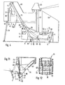
- the frame part 31 accommodates all essential parts of the metering device.
- This frame part 31 is trapezoidal and consists essentially of the mutually parallel profiles 29 and 98 and the inclined profiles 4 and 5.
- the profile 4 is connected to the struts 27 and 28 of the barrel axis 26.
- the frame part 31 essentially receives the fixed end walls 7 for the storage spaces to be formed for the additives, as well as the base plate 1, in which the metering closures 2 are arranged.
- the storage rooms for the additives can be enlarged by detachable walls 8.
- part 14 of the elevator track which guides the feeder box 12, is located in the extension of the profile 5.
- the profile 19 of the frame part 32 is provided with the struts 94 to which the fifth wheel coupling 95 is fastened, so that a semi-trailer is obtained overall.
- the frame part 32 is pivoted up and is supported by the strut 23, which now acts as a support.
- the frame part 23 receives the mixer 16, which rests on the profiles 18.
- the transfer hopper is designated, with which the mix on transport; vehicles, for example, is delivered to a car mixer.
- a guardrail is designated, which is additionally attached in the operating position and with 17 the cement scale, which is permanently installed.
- control elements of the metering device of the frame part 31 are combined in the control station 9, in particular the display heads 11 for the additives.
- the control elements for the mixer 16, the water addition (not shown in detail) and the cement scales 17 can also be installed in the control station.
- the control station takes up a position that takes advantage of the space available during transport and is very convenient for the operating position.
- the frame part 31 is also placed on the supports 3.
- a ladder 21 completes the operating position.
- a strut 30 serves to additionally stiffen the frame part 31.
- the supports 6 have a similar task, which are indicated in FIG. 1, but are omitted in the other illustrations to improve the overview.
- the feeder box 12 assumes its metering position in the illustration in FIG. 3. It is located under the dosing caps 2 ..
- the . Feeder box conveyor consists of different sections.
- the lower section, in which the feeder box in FIG. 3 is located, is slightly inclined and is covered by the profiles 98.
- This section is adjoined by an intermediate section 59 which has an inclination of approximately 20 degrees and which on the one hand has the task of facilitating and facilitating the pulling out of the feeder box under the metering closures 2 and of creating it in transition to the feeder track section which consists of the parts 13 and 14 and has an incline of about 60 degrees.
- the section 59 is intended to reduce the speed of the feed box during the lowering movement, so that the feed box only enters its lowermost section at a moderate speed.
- the cable 42 that moves the feeder box 12 is driven by the winch 15.
- the cable runs from the winch to a deflection roller 55 on the feeder box and from here back to a starting damping device 25, which will be described in more detail below.
- a damping device is designated, which has the task of damping the lowering movement of the feeder box in order to stress the dosing device and in particular the weighing device as little as possible. Further details are shown in FIGS. 11 and 12 and are described in more detail below.
- FIG. -4 differs from that of FIG. 3 essentially in that the mixer 16 with the funnel 20 ' is replaced by a storage device 47. This arrangement is to be selected if the aggregates and the cement are dry-dosed and, for example, filled into an automatic mixer, which then takes over the mixing.
- FIG. 4 While the embodiment according to FIG. 2 reveals that fillings 99 are made laterally by means of the protective walls 90, which allow driving with shovel loaders to fill the storage rooms, the embodiment of FIG. 4 provides that star-like boxes are provided which are provided by the Partitions 44 are divided and a scraping device 45 is arranged on the wall 43, which, as is known per se, conveys the aggregates to the center of these star-like storage rooms.
- Fig. 4 also shows that outer walls 40 or 38 and 39 can be attached if desired.
- the frame part 31 is also trapezoidal in the embodiment of FIG. 4, but the profile 29 is missing.
- FIGS. 5 and 6 show essential parts of the weighing device and the metering device.
- the feeder box 12 which can have a construction, for example, as described in German Offenlegungsschrift 25 04 301, is in FIG. 5 in its metering or weighing position. It is located in the area of the lower section 60 of the feeder box conveyor. Of the four rollers 50 and 54, the pair of rollers 50 are carried by the subframe 52,
- the two frame parts on both sides of the feeder box 12 are connected to one another by the profiles 58.
- an additional pair of support rollers 56 is also provided, which has run onto the run-up rail piece 57 of the auxiliary frame 52, as a result of which the pair of rollers 54 is also relieved.
- the feeder box thus hangs in the auxiliary frame 52 by means of the rollers 50 and 56.
- the auxiliary frame 52 is, as is known per se, connected to the corresponding parts of the balance 53, as is indicated schematically in FIG. 5.
- the feeder box is filled via the metering closures 2, which are shown in FIG. 6 but not in FIG. 5.
- the dash-dotted lines 61 indicate the subdivision of the storage rooms for the aggregates.
- section 59 has an inclination of approximately 20 degrees, the inclination of section 60 is less and is approximately 5 degrees.
- the front wall 91 of the feeder box 12, as shown in FIG. 6, is formed by flaps which are movable around the joints 92, so that the interior of the feeder box 12 is also accessible in its lowered position, for example for the calibration of the balance.
- the damping device 24 consists essentially of the swivel arm 68 which is movable about the joint 69 and which is under the action of the spring 72 and on both dynamic dampers 77.
- the dampers 77 in particular have such a configuration as is known from motor vehicles.
- the attachment of the springs 72 at the point 73 results in two positions for the swivel arm 68.
- the feeder box 12 hits with its front part against the thrust roller 70 on the swivel arm 68 and takes the swivel arm with it.
- the movement of the feeder box 12 is brought to a standstill on the path labeled "X".
- the arrangement of the spring 72 means that the roller 70 is lifted off the stationary feeder box 12, so that the movement of the feeder box is not impaired during the weighing process.
- a driver lug 71 is arranged, which is effective when the feeder box is in the elevator movement. This feeder box nose 71 resets the swivel arm 68 when the elevator moves.
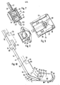
- the starting damping device 25 is also provided for the starting movement, the details of which can be seen from the illustration in FIGS. 7 to 9.
- the starting damping device consists of a housing 74 in which the springs 75, which are designed as rubber buffers, are arranged.
- the pull cable 42 is connected by means of a sleeve 100 to a pull rod 101, the upper end of which carries a plate 82 which is connected to the yoke 78 arranged outside the housing 74.
- the rubber springs 75 When pulling on the cable 42, the rubber springs 75 are therefore compressed and also the hydraulic dampers 77.
- the starting shock becomes strong.
- the dampers 77 which can be dampers of motor vehicles, for example, suppress any vibrations.
- the entire housing 74 is mounted so as to be movable around the joints 79 at the upper end of the elevator track 14. Between the housing 74 and the yoke 78 there is also a switch 80, which is connected to a timing relay, so that the winch 15 is turned off when there is a strong resistance during the lifting process, which leads to a strong permanent compression of the springs.
- the spring 81 supports the rubber springs 75.
- FIG. 10 shows the elevator path and the movement of the feeder box 12.
- the feeder box In the lowest position, the feeder box is in the filling position or in the dosing position.
- the feeder box has only a slight incline. If the elevator is switched on, the feed box moves from section 60 to section 59 in a certain inclined position, which facilitates and enables pulling out from under the metering flaps and also improves the starting process.
- Section 13 or section 14 adjoins section 59 of the elevator track.
- a recess 83 is provided, which leads to the rollers 50 being lowered, as a result of which the emptying flap of the feeder box opens, as is known for this type of feeder box.
- the auxiliary rollers 65 on the feeder box prevent the rollers 5L from sinking into the recess or the end of the feeder box 12 from sinking during the emptying process.
- the height of the hinge 41 is to be chosen from approximately 3.10 m above the ground. The height during road transport then does not exceed 4.00 m and a moderate overall length is also obtained.
Landscapes
- Chemical & Material Sciences (AREA)
- Dispersion Chemistry (AREA)
- Preparation Of Clay, And Manufacture Of Mixtures Containing Clay Or Cement (AREA)
- Filling Or Emptying Of Bunkers, Hoppers, And Tanks (AREA)
- On-Site Construction Work That Accompanies The Preparation And Application Of Concrete (AREA)
- Devices For Post-Treatments, Processing, Supply, Discharge, And Other Processes (AREA)
Priority Applications (1)
| Application Number | Priority Date | Filing Date | Title |
|---|---|---|---|
| AT80104294T ATE3516T1 (de) | 1979-07-25 | 1980-07-22 | Vorrichtung zur dosierung und hochfoerderung der zuschlagstoffe zur herstellung von beton. |
Applications Claiming Priority (2)
| Application Number | Priority Date | Filing Date | Title |
|---|---|---|---|
| DE19792930154 DE2930154A1 (de) | 1979-07-25 | 1979-07-25 | Betonbereitungsanlage oder trockendosierstation |
| DE2930154 | 1979-07-25 |
Publications (3)
| Publication Number | Publication Date |
|---|---|
| EP0023338A2 true EP0023338A2 (fr) | 1981-02-04 |
| EP0023338A3 EP0023338A3 (en) | 1981-02-18 |
| EP0023338B1 EP0023338B1 (fr) | 1983-05-25 |
Family
ID=6076744
Family Applications (1)
| Application Number | Title | Priority Date | Filing Date |
|---|---|---|---|
| EP80104294A Expired EP0023338B1 (fr) | 1979-07-25 | 1980-07-22 | Appareil pour le dosage et le levage des composants pour la préparation du béton |
Country Status (5)
| Country | Link |
|---|---|
| US (1) | US4339204A (fr) |
| EP (1) | EP0023338B1 (fr) |
| AT (1) | ATE3516T1 (fr) |
| CA (1) | CA1147320A (fr) |
| DE (1) | DE2930154A1 (fr) |
Cited By (7)
| Publication number | Priority date | Publication date | Assignee | Title |
|---|---|---|---|---|
| FR2512381A1 (fr) * | 1981-09-05 | 1983-03-11 | Elba Werk Maschinen Gmbh & Co | Dispositif de dosage en serie pour la preparation du beton par gachees successives |
| FR2518009A1 (fr) * | 1981-12-11 | 1983-06-17 | Elba Werk Maschinen Gmbh & Co | Installation mobile pour preparer le beton |
| EP0807502A1 (fr) * | 1996-05-15 | 1997-11-19 | Simem S.p.A. | Système mobile pour mélanger du béton, transportable sur un véhicule |
| CN101870140A (zh) * | 2010-06-01 | 2010-10-27 | 美巢集团股份公司 | 聚合物水泥防水涂料的复合粉料生产设备 |
| ITCT20130003A1 (it) * | 2013-02-14 | 2014-08-15 | Euromecc Srl | Unita' di mescolazione mobile con struttura di sostegno richiiudibile a quadrilatero articolato |
| CN105965696A (zh) * | 2016-07-13 | 2016-09-28 | 芜湖恒固混凝土材料有限公司 | 混凝土粉料储料设备 |
| CN106239732A (zh) * | 2016-07-13 | 2016-12-21 | 芜湖恒固混凝土材料有限公司 | 具有过滤网的混凝土粉料储料设备 |
Families Citing this family (17)
| Publication number | Priority date | Publication date | Assignee | Title |
|---|---|---|---|---|
| US4525070A (en) * | 1983-04-08 | 1985-06-25 | Gressette Jr Tatum W | Rotary mixing apparatus |
| US4792234A (en) * | 1986-01-06 | 1988-12-20 | Port-A-Pour, Inc. | Portable concrete batch plant |
| FR2607053B1 (fr) * | 1986-11-24 | 1990-08-03 | Mebi | Centrale mobile de fabrication de beton |
| GB2213397B (en) * | 1987-12-15 | 1991-10-23 | James Ernest Belgium | Detachable mixer and container assembly |
| US5149192A (en) * | 1988-09-30 | 1992-09-22 | Mixer Products, Inc. | System for mixing cementitious construction materials |
| US5203628A (en) * | 1988-09-30 | 1993-04-20 | Hamm Family Partnership | Portable batch mixing apparatus for cementitious construction materials |
| USD324688S (en) | 1989-08-10 | 1992-03-17 | Brownwood Ross Co. Inc. | Combined mobile concrete batch plant and mixing unit |
| US5121989A (en) * | 1990-03-12 | 1992-06-16 | Mcneilus Truck And Manufacturing, Inc. | Transportable concrete batching apparatus |
| US5411329A (en) * | 1993-06-28 | 1995-05-02 | Perry; L. F. | Portable large volume cement mixer for batch operations |
| US5474379A (en) * | 1995-03-31 | 1995-12-12 | Perry; L. F. | Portable high volume cement mixer |
| FI2408U1 (fi) | 1996-02-02 | 1996-04-29 | Tecwill Oy | Betoniasema |
| US5785421A (en) * | 1996-10-22 | 1998-07-28 | Milek; Robert C. | Mobile modular concrete batch plant |
| US6527428B2 (en) * | 2000-09-20 | 2003-03-04 | Guntert & Zimmerman Const. Div., Inc. | High volume portable concrete batching and mixing plant having compulsory mixer with overlying supported silo |
| GR1006037B (el) * | 2006-11-16 | 2008-10-13 | Οδυσσεας Σπανος Α.Β.Ε.Τ.Ε. | Μεταφερομενη γραμμη παραγωγης σκυροδεματος |
| US10919010B2 (en) * | 2017-06-15 | 2021-02-16 | Albert Posthumus | Elevating animal feed mixing system |
| WO2022198977A1 (fr) * | 2021-03-26 | 2022-09-29 | 中铁科工集团轨道交通装备有限公司 | Centrale à béton mobile ayant un système de levage hydraulique |
| CN116766401B (zh) * | 2023-06-13 | 2024-01-30 | 徐州经济技术开发区诚意商品混凝土有限公司 | 一种混凝土送料装置 |
Family Cites Families (11)
| Publication number | Priority date | Publication date | Assignee | Title |
|---|---|---|---|---|
| DE1287496B (fr) * | 1969-01-16 | |||
| US2687285A (en) * | 1952-07-19 | 1954-08-24 | Delmar W Fisher | Portable batcher plant |
| AT265088B (de) * | 1960-06-24 | 1968-09-25 | Domenico Dr Ing Domenighetti | Fahrbare Dosieranlage |
| GB966112A (en) * | 1960-06-24 | 1964-08-06 | Costante Domenighetti | Improvements in or relating to mobile batching and mixing units |
| DE1182573B (de) * | 1962-07-24 | 1964-11-26 | Kabag Karlsruhe Baumasch | Bremsvorrichtung fuer Materialaufzuege an Betonbereitungsanlagen |
| DE1242496B (de) * | 1962-09-25 | 1967-06-15 | Ernst Ewald Kuehner | Betonbereitungsanlage |
| DE1887645U (de) * | 1963-08-13 | 1964-02-18 | Rex Hünnebeck G.m.b.H., Lintorf (Bez. Düsseldorf) | Als Einheit verfahrbare Betonmischanlage |
| CH450263A (de) * | 1965-03-13 | 1968-01-15 | Elba Werk Maschinen Gmbh & Co | Fahrbare Vorrichtung zur Herstellung von Beton |
| US3343688A (en) * | 1966-09-06 | 1967-09-26 | Harsco Corp | Mobile concrete batching unit |
| DE2106334A1 (de) * | 1971-02-10 | 1971-08-19 | Bouvagnet, Paul Me>lai (Frank reich) | Ortsbeweglich^ Betonmist hanlage |
| NL7803801A (nl) * | 1978-04-11 | 1979-10-15 | Mulder S Fabriek Van Rollend M | Verplaatsbare installatie voor het mengen van beton. |
-
1979
- 1979-07-25 DE DE19792930154 patent/DE2930154A1/de not_active Withdrawn
-
1980
- 1980-07-22 EP EP80104294A patent/EP0023338B1/fr not_active Expired
- 1980-07-22 AT AT80104294T patent/ATE3516T1/de not_active IP Right Cessation
- 1980-07-22 US US06/171,128 patent/US4339204A/en not_active Expired - Lifetime
- 1980-07-24 CA CA000356908A patent/CA1147320A/fr not_active Expired
Cited By (8)
| Publication number | Priority date | Publication date | Assignee | Title |
|---|---|---|---|---|
| FR2512381A1 (fr) * | 1981-09-05 | 1983-03-11 | Elba Werk Maschinen Gmbh & Co | Dispositif de dosage en serie pour la preparation du beton par gachees successives |
| FR2518009A1 (fr) * | 1981-12-11 | 1983-06-17 | Elba Werk Maschinen Gmbh & Co | Installation mobile pour preparer le beton |
| EP0807502A1 (fr) * | 1996-05-15 | 1997-11-19 | Simem S.p.A. | Système mobile pour mélanger du béton, transportable sur un véhicule |
| US5797676A (en) * | 1996-05-15 | 1998-08-25 | Simem S.P.A. | Mobile concrete mixing system transportable onto trucks |
| CN101870140A (zh) * | 2010-06-01 | 2010-10-27 | 美巢集团股份公司 | 聚合物水泥防水涂料的复合粉料生产设备 |
| ITCT20130003A1 (it) * | 2013-02-14 | 2014-08-15 | Euromecc Srl | Unita' di mescolazione mobile con struttura di sostegno richiiudibile a quadrilatero articolato |
| CN105965696A (zh) * | 2016-07-13 | 2016-09-28 | 芜湖恒固混凝土材料有限公司 | 混凝土粉料储料设备 |
| CN106239732A (zh) * | 2016-07-13 | 2016-12-21 | 芜湖恒固混凝土材料有限公司 | 具有过滤网的混凝土粉料储料设备 |
Also Published As
| Publication number | Publication date |
|---|---|
| EP0023338A3 (en) | 1981-02-18 |
| DE2930154A1 (de) | 1981-02-12 |
| ATE3516T1 (de) | 1983-06-15 |
| US4339204A (en) | 1982-07-13 |
| EP0023338B1 (fr) | 1983-05-25 |
| CA1147320A (fr) | 1983-05-31 |
Similar Documents
| Publication | Publication Date | Title |
|---|---|---|
| EP0023338B1 (fr) | Appareil pour le dosage et le levage des composants pour la préparation du béton | |
| DE1964222A1 (de) | Betonliefermischer | |
| DE3135197C2 (de) | Transportable, demontierbare Siloanlage zur Lagerung und Zuteilung unterschiedlicher Schüttgutkomponenten | |
| DE1759033A1 (de) | Tansportable Turmkonstruktion,insbesondere Mischturm | |
| DE2635969C2 (de) | Fahrbarer Bandförderer | |
| DE1242496B (de) | Betonbereitungsanlage | |
| DE2301428A1 (de) | Abstellvorrichtung fuer kraftfahrzeuge | |
| EP0456072A1 (fr) | Dispositif de parcage de véhicules automobiles sur des plates-formes | |
| AT243149B (de) | Vorrichtung zum Beschicken von Automischern od. dgl. mit Baustoffen | |
| DE3709360C2 (de) | Transportable Betonbereitungsanlage | |
| DE19807416C2 (de) | Verfahren und Vorrichtung zum Simulieren von Fahrstrecken, insbesondere für Geländewagen | |
| DE1901867A1 (de) | Betonmischmaschine | |
| DE2837970C2 (de) | Betonbereitungsanlage | |
| DE3225662A1 (de) | Kippvorrichtung fuer strassenfahrzeuge | |
| DE820110C (de) | Misch- und Foerdereinrichtung | |
| DE7600208U1 (de) | Füllvorrichtung für Steinformmaschine | |
| DE1953290A1 (de) | Hubwerk fuer Transportbehaelter | |
| DE1459284C2 (de) | Betonbereitu ngsanlage | |
| DE3337442A1 (de) | Foerdervorrichtung zum aufnehmen und weiterfoerdern von inerten stoffen, wie sand, kies, zement usw. | |
| DE1484738A1 (de) | Vierpunktabstuetzung von steifen Koerpern auf Fahrwerken,wie Bagger,Absetzer od.dgl. | |
| DE1215008B (de) | Fahrzeug mit kippbarer Ladebruecke und Transportmulde fuer fliessfaehiges Gut | |
| DE2849732A1 (de) | Foerdervorrichtung an muellwagen o.ae. fahrzeugen | |
| DE1584826A1 (de) | Fahrbare Anlage zur Herstellung von Beton | |
| DE3049217A1 (de) | "fahrzeug fuer den transport von fertiggaragen, raumzellen o.dgl." | |
| DE7806153U1 (de) | Transportierbarer behaelter fuer trockenputz |
Legal Events
| Date | Code | Title | Description |
|---|---|---|---|
| PUAI | Public reference made under article 153(3) epc to a published international application that has entered the european phase |
Free format text: ORIGINAL CODE: 0009012 |
|
| PUAL | Search report despatched |
Free format text: ORIGINAL CODE: 0009013 |
|
| AK | Designated contracting states |
Designated state(s): AT BE CH FR GB IT LU NL SE |
|
| AK | Designated contracting states |
Designated state(s): AT BE CH FR GB IT LU NL SE |
|
| 17P | Request for examination filed |
Effective date: 19810624 |
|
| ITF | It: translation for a ep patent filed | ||
| GRAA | (expected) grant |
Free format text: ORIGINAL CODE: 0009210 |
|
| AK | Designated contracting states |
Designated state(s): AT BE CH FR GB IT LI LU NL SE |
|
| PGFP | Annual fee paid to national office [announced via postgrant information from national office to epo] |
Ref country code: LU Payment date: 19830525 Year of fee payment: 4 |
|
| REF | Corresponds to: |
Ref document number: 3516 Country of ref document: AT Date of ref document: 19830615 Kind code of ref document: T |
|
| ET | Fr: translation filed | ||
| PG25 | Lapsed in a contracting state [announced via postgrant information from national office to epo] |
Ref country code: LU Free format text: LAPSE BECAUSE OF NON-PAYMENT OF DUE FEES Effective date: 19830731 |
|
| PLBE | No opposition filed within time limit |
Free format text: ORIGINAL CODE: 0009261 |
|
| STAA | Information on the status of an ep patent application or granted ep patent |
Free format text: STATUS: NO OPPOSITION FILED WITHIN TIME LIMIT |
|
| 26N | No opposition filed | ||
| PGFP | Annual fee paid to national office [announced via postgrant information from national office to epo] |
Ref country code: BE Payment date: 19840930 Year of fee payment: 5 |
|
| PGFP | Annual fee paid to national office [announced via postgrant information from national office to epo] |
Ref country code: NL Payment date: 19870731 Year of fee payment: 8 |
|
| PGFP | Annual fee paid to national office [announced via postgrant information from national office to epo] |
Ref country code: SE Payment date: 19890704 Year of fee payment: 10 Ref country code: CH Payment date: 19890704 Year of fee payment: 10 |
|
| PGFP | Annual fee paid to national office [announced via postgrant information from national office to epo] |
Ref country code: FR Payment date: 19890717 Year of fee payment: 10 |
|
| PGFP | Annual fee paid to national office [announced via postgrant information from national office to epo] |
Ref country code: AT Payment date: 19890725 Year of fee payment: 10 |
|
| PG25 | Lapsed in a contracting state [announced via postgrant information from national office to epo] |
Ref country code: BE Effective date: 19890731 |
|
| PGFP | Annual fee paid to national office [announced via postgrant information from national office to epo] |
Ref country code: GB Payment date: 19890731 Year of fee payment: 10 |
|
| BERE | Be: lapsed |
Owner name: STETTER G.M.B.H. Effective date: 19890731 |
|
| PG25 | Lapsed in a contracting state [announced via postgrant information from national office to epo] |
Ref country code: NL Effective date: 19900201 |
|
| NLV4 | Nl: lapsed or anulled due to non-payment of the annual fee | ||
| PG25 | Lapsed in a contracting state [announced via postgrant information from national office to epo] |
Ref country code: GB Effective date: 19900722 Ref country code: AT Effective date: 19900722 |
|
| PG25 | Lapsed in a contracting state [announced via postgrant information from national office to epo] |
Ref country code: SE Effective date: 19900723 |
|
| ITTA | It: last paid annual fee | ||
| PG25 | Lapsed in a contracting state [announced via postgrant information from national office to epo] |
Ref country code: LI Effective date: 19900731 Ref country code: CH Effective date: 19900731 |
|
| GBPC | Gb: european patent ceased through non-payment of renewal fee | ||
| REG | Reference to a national code |
Ref country code: CH Ref legal event code: PL |
|
| PG25 | Lapsed in a contracting state [announced via postgrant information from national office to epo] |
Ref country code: FR Effective date: 19910329 |
|
| REG | Reference to a national code |
Ref country code: FR Ref legal event code: ST |
|
| EUG | Se: european patent has lapsed |
Ref document number: 80104294.6 Effective date: 19910402 |