EP0023480A1 - Dispositif pour faire varier l'instant d'injection d'une pompe d'injection de carburant pour moteurs à combustion interne à injection - Google Patents
Dispositif pour faire varier l'instant d'injection d'une pompe d'injection de carburant pour moteurs à combustion interne à injection Download PDFInfo
- Publication number
- EP0023480A1 EP0023480A1 EP19800890082 EP80890082A EP0023480A1 EP 0023480 A1 EP0023480 A1 EP 0023480A1 EP 19800890082 EP19800890082 EP 19800890082 EP 80890082 A EP80890082 A EP 80890082A EP 0023480 A1 EP0023480 A1 EP 0023480A1
- Authority
- EP
- European Patent Office
- Prior art keywords
- centrifugal weights
- rotation
- injection pump
- angle
- injection
- Prior art date
- Legal status (The legal status is an assumption and is not a legal conclusion. Google has not performed a legal analysis and makes no representation as to the accuracy of the status listed.)
- Granted
Links
- 238000002347 injection Methods 0.000 title claims abstract description 36
- 239000007924 injection Substances 0.000 title claims abstract description 36
- 239000000446 fuel Substances 0.000 title claims abstract description 7
- 238000002485 combustion reaction Methods 0.000 title claims abstract description 4
- 230000007246 mechanism Effects 0.000 title abstract description 5
- 230000001154 acute effect Effects 0.000 claims abstract description 4
- 239000007921 spray Substances 0.000 claims description 6
- 230000009471 action Effects 0.000 claims description 2
- 238000000034 method Methods 0.000 description 3
- 230000008569 process Effects 0.000 description 3
- 230000008878 coupling Effects 0.000 description 2
- 238000010168 coupling process Methods 0.000 description 2
- 238000005859 coupling reaction Methods 0.000 description 2
- 238000013016 damping Methods 0.000 description 2
- 238000010586 diagram Methods 0.000 description 2
- 238000005096 rolling process Methods 0.000 description 2
- 238000007789 sealing Methods 0.000 description 2
- 210000003813 thumb Anatomy 0.000 description 2
- 230000006835 compression Effects 0.000 description 1
- 238000007906 compression Methods 0.000 description 1
- 230000001419 dependent effect Effects 0.000 description 1
- 238000006073 displacement reaction Methods 0.000 description 1
- 230000009467 reduction Effects 0.000 description 1
Images
Classifications
-
- F—MECHANICAL ENGINEERING; LIGHTING; HEATING; WEAPONS; BLASTING
- F02—COMBUSTION ENGINES; HOT-GAS OR COMBUSTION-PRODUCT ENGINE PLANTS
- F02D—CONTROLLING COMBUSTION ENGINES
- F02D1/00—Controlling fuel-injection pumps, e.g. of high pressure injection type
- F02D1/16—Adjustment of injection timing
- F02D1/162—Adjustment of injection timing by mechanical means dependent on engine speed for angular adjustment of driving and driven shafts
-
- F—MECHANICAL ENGINEERING; LIGHTING; HEATING; WEAPONS; BLASTING
- F16—ENGINEERING ELEMENTS AND UNITS; GENERAL MEASURES FOR PRODUCING AND MAINTAINING EFFECTIVE FUNCTIONING OF MACHINES OR INSTALLATIONS; THERMAL INSULATION IN GENERAL
- F16D—COUPLINGS FOR TRANSMITTING ROTATION; CLUTCHES; BRAKES
- F16D3/00—Yielding couplings, i.e. with means permitting movement between the connected parts during the drive
- F16D3/02—Yielding couplings, i.e. with means permitting movement between the connected parts during the drive adapted to specific functions
- F16D3/10—Couplings with means for varying the angular relationship of two coaxial shafts during motion
Definitions
- Injection adjusters for fuel injection pumps which are equipped with centrifugal weights, have the task of changing the relative angular position of drive shafts and injection pump camshafts as a function of the speed, the centrifugal weights adjusting a coupling element between the drive shaft and the injection camshaft depending on their position. Since the drive torque is conducted via this clutch, the centrifugal weights are not only loaded by the force of one or more springs, but also by the torque passed through the clutch, which is required to drive the injection pump camshaft.
- the torque required to drive single or multi-cylinder injection pumps is not constant, however, but depends on whether a pump element is currently carrying out a delivery process or not.
- the torque is influenced by the speed, the fuel delivery rate, the diameter of the fuel pressure line and by numerous other parameters. Since the actual delivery stroke of the injection pump only extends over a few angular degrees, there is a big difference between the average and the maximum torque. This leads to the fact that the adjusting device visits an angular position which results from the average torque, but that it is adjusted or pushed back from this position during the duration of the peak torque. The adjustment device searches in the free phase between the individual pump strokes their starting position again. This back pressure of the adjusting device has to be given more and more attention lately, since the peak pressures in injection systems have reached ever higher values up to 1000 bar and more.
- the invention now relates to an injection adjuster for fuel injection pumps of injection internal combustion engines, which is equipped with centrifugal weights which are loaded centripetal by at least one spring and are guided to be displaceable under the action of the centrifugal force, the injection pump shaft being connected to the drive shaft in an adjustable angle of rotation and the centrifugal weights when moving outward, adjust the injection pump shaft relative to the drive in the direction of rotation.
- the object of the invention is to prevent or at least largely reduce the backpressure of the injection pump camshaft at the moment of delivery, without increasing the design effort or the forces transmitted.
- the invention consists essentially in that the Centrifugal weights are guided at an acute angle to the radial, leading in the direction of rotation can be moved outward. If the torque is increased during the stroke of a pump piston, this acts in the sense of a short-term speed reduction, that is to say in the sense of a centripetal pushing back of the centrifugal weights. However, because the centrifugal weights are advanced in the direction of rotation, the centrifugal weights are given an outward impulse by the inertia of the centrifugal weights.
- the angle between the guiding direction of the centrifugal weights and the radial is advantageously between 5 ° and 25 °, preferably 10 to 20 °. This angle can be determined empirically and good results have been found within the limits mentioned.
- the flyweights can be guided in tracks.
- the centrifugal weights are pivotally mounted about pivot axes, and in this case, according to the invention, the condition that the centrifugal weights are guided so that they can be moved outward in the direction of rotation is achieved in that the pivot axes are at an angle deviating from 90 ° to that through the longitudinal center of the Radials going swivel axes stand and the normals on the swivel axes to the radial run obliquely outwards in the direction of rotation.
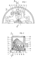
- FIG. 1 and 2 show a spray adjuster
- Fig. 1 shows a section along line I-I der.Fig. 2
- Fig. 2 shows a section along line II-II-II of Fig. 1-.
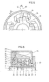
- 3 and 4 show diagrams. 5 and 6 show another embodiment of a spray adjuster, wherein Fig. 5 shows a cross section and FIG. 6 shows a longitudinal section.
- 1 is the shaft of the injection pump, not shown.
- a hub 4 is fixedly attached to the shaft 1 by means of a disc spring 2 and a nut 3 and has the centrifugal weight carrier 5 in its left part.
- the centrifugal weight carrier 5 has four arms with fork-shaped recesses, in which the centrifugal weights 7 are rotatably mounted via the bolts 6.
- the movement of the flyweights 7 is transmitted via thumb 8, which have a pitch curve 9 on their part facing the axis, to an annular plate 10, which is firmly attached to a sliding sleeve 11.
- the contact between thumb 8 and annular plate 10 is by one or more pressure springs 12, 13 are maintained, which are clamped between the sliding sleeve 11 and a driver plate 14.
- the driver plate 14 has a hub part which is mounted on the hub 4 with its inner diameter.
- the hub 4 and the hub part of the driver plate 14 each have external teeth 15 and 16, at least one of which is helical in the form of a steep thread.
- the sliding sleeve 11 has the toothings 17 and 18 corresponding to these toothings.
- a displacement of the sliding sleeve 11 causes a relative rotation between the hub 4 and the driver plate 14.
- a housing 19 is fastened to the driver plate 14.
- the housing 19 is filled with oil and is sealed to the outside via sealing rings 20.
- the drive takes place through a flexible coupling, not shown, via slug 21 on the driver plate.
- the centrifugal weights 7 are pressed outwards, whereby the pre-injection angle is increased as the speed increases.
- These flyweights are not only loaded by the springs 12 and 13 in the centripetal direction.
- the torque required for the operation of the injection pump must be transmitted to the injection pump shaft 1 and this torque exerts a push-back force on the sliding sleeve 11 via the teeth 15, 16, which must be added to the force of the springs 12, 13. If this push-back force is smaller, the centrifugal weights can swing out further and if the push-back force is larger, the centrifugal weights would swing out less far at the same speed, although these differences are only slight.
- the one to be transferred by the spray adjuster Torque is not constant, however, but has a sharp increase in each delivery process, ie in the injection pump, which causes a corresponding brief increase in the push-back force. Due to the inevitable elasticity of the drive, the increased torque causes a strong angular deceleration.
- the bolts 6, about which the centrifugal weights 7 pivot are usually at an angle of 90 ° to the radial. As shown in FIG. 1, but are of the pivot axes at a 90 0 angle other than ⁇ to the passing through the longitudinal center of the pivotal axes 6 radials 22, wherein the normal to the pivot axis 6 relative to the radial 22 extending obliquely outwardly in the rotational direction 24.
- the centrifugal weights thus pivot in the direction of these normals and the pivot plane 23 of the centrifugal weights is therefore not in the radial 22, but rather makes an angle ⁇ with the radial 22.
- the centrifugal weights 7 are guided at an acute angle D0 leading to the radial 22 in the direction of rotation and can be displaced outwards.
- the sleeve pushing force thus caused acts against the push-back force from the torque, which would swing the centrifugal weight inwards.
- the angle ⁇ by which the pivot plane 23 of the centrifugal weights against the Radial 22 is rotated the push-back forces and the pushing force resulting from the mass force 25 keep the balance and a push-back of the sleeve is prevented.
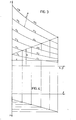
- the pushing force F is plotted over the sleeve path s.
- the so-called pendulum curve a results.
- the pendulum curves a l - a 6 are plotted for a plurality of speeds n 1 to n 6 over the sleeve travel s or over the adjustment angle ⁇ correspondingly co-operating on the steep thread on the sleeve.
- the average drive torque passed through the injection adjuster causes a pushing back force c on the sleeve via the steep thread. If the respective spring force b is added to this force c, the total counterforce F is obtained - if the friction is neglected.
- the intersections of this total force F with the pendulum curves a l - a 6 result in the relationship between the speed n and the adjustment angle ⁇ , which in the 4 is shown.
- 5 and 6 show a spray adjuster of a type in which the relationship between the swivel angle of the centrifugal weights and the sleeve path or adjustment angle is given by rolling curves which are attached to the centrifugal weights themselves.
- a disc 28 is fastened with the disc spring 2 and the nut 3, which in its part shown on the left has a circular plate 29 and which has a toothing 30, which can be a straight toothing or a screw toothing.
- a sliding sleeve 31 is in constant engagement with this toothing 30 by means of a toothing 32 corresponding thereto.
- On four arms 33 of the sliding sleeve 31 four centrifugal weights 35 are pivotally mounted via pivot pins 34, which are Support on the surface 37 of the hub via roller curves 36 attached to its back.
- a compression spring 38 is arranged between the housing 39 fastened on the hub 28 and the sliding sleeve 31 and presses the sleeve together with the centrifugal weights pivotably mounted on it against the surfaces 37 of the hub 28.
- the sleeve 31 has a second toothing 40, which with a Teeth 41 of a sleeve 42 is in constant engagement.
- Two sealing rings 43 serve to seal the sleeve 42 guided out of the oil-filled housing 39.
- the sleeve will assume an equilibrium position depending on the speed, spring force and average torque, which is determined by the shape of the rolling curves 36 on the flyweight back and which the adjustment angle between the hub 28 and the sleeve 42 sets.
- a mass force acting in the event of a deceleration is obtained in the center of mass of the centrifugal weight, which counteracts the pushback caused by the torque passed through .
- the angle of inclination oC- which is necessary for the balance of the forces on the sleeve, depends on the parameters of the system and, like the embodiment according to FIGS. 1 and 2, is between 5 ° and 25 °, preferably between 10 ° and 20 °. Due to an asymmetrical design of the flyweights, the available space can be used more cheaply. A smaller or larger number of flyweights is also possible.
Landscapes
- Engineering & Computer Science (AREA)
- General Engineering & Computer Science (AREA)
- Mechanical Engineering (AREA)
- Chemical & Material Sciences (AREA)
- Combustion & Propulsion (AREA)
- High-Pressure Fuel Injection Pump Control (AREA)
Applications Claiming Priority (2)
| Application Number | Priority Date | Filing Date | Title |
|---|---|---|---|
| AT5207/79 | 1979-07-27 | ||
| AT520779 | 1979-07-27 |
Publications (2)
| Publication Number | Publication Date |
|---|---|
| EP0023480A1 true EP0023480A1 (fr) | 1981-02-04 |
| EP0023480B1 EP0023480B1 (fr) | 1982-05-05 |
Family
ID=3573159
Family Applications (1)
| Application Number | Title | Priority Date | Filing Date |
|---|---|---|---|
| EP19800890082 Expired EP0023480B1 (fr) | 1979-07-27 | 1980-07-22 | Dispositif pour faire varier l'instant d'injection d'une pompe d'injection de carburant pour moteurs à combustion interne à injection |
Country Status (4)
| Country | Link |
|---|---|
| EP (1) | EP0023480B1 (fr) |
| DE (1) | DE3060369D1 (fr) |
| PL (1) | PL125111B1 (fr) |
| YU (1) | YU189780A (fr) |
Cited By (2)
| Publication number | Priority date | Publication date | Assignee | Title |
|---|---|---|---|---|
| WO1987007344A1 (fr) * | 1986-05-19 | 1987-12-03 | Allied Corporation | Dispositif anti-jeu a cannelures |
| EP0292224A1 (fr) * | 1987-05-18 | 1988-11-23 | Paul Clifford Green | Accouplement mécanique |
Citations (6)
| Publication number | Priority date | Publication date | Assignee | Title |
|---|---|---|---|---|
| DE1971830U (de) * | 1965-09-10 | 1967-11-02 | Kugelfischer G Schaefer & Co | Schwingungsdaempfer, insbesondere fuer das foerdermengenverstellglied der einspritzpumpe einer brennkraftmaschine. |
| DE1994205U (de) * | 1968-07-15 | 1968-09-19 | Friedmann & Maier Ag | Spritzversteller. |
| AT284548B (de) * | 1967-12-22 | 1970-09-25 | Friedmann & Maier Ag | Einrichtung zur Verstellung des Spritzbeginnes einer Einspritzpumpe für Brennkraftmaschinen |
| AT287402B (de) * | 1967-09-01 | 1971-01-25 | Friedmann & Maier Ag | Spritzversteller für Einspritzpumpen für Einspritzbrennkraftmaschinen |
| AT295246B (de) * | 1968-03-18 | 1971-12-27 | Friedmann & Maier Ag | Einrichtung zur Verstellung des Spritzbeginnes von Brennstoffeinspritzpumpen |
| AT295245B (de) * | 1967-09-01 | 1971-12-27 | Friedmann & Maier Ag | Spritzversteller für Einspritzpumpen für Einspritzbrennkraftmaschinen |
-
1980
- 1980-07-22 EP EP19800890082 patent/EP0023480B1/fr not_active Expired
- 1980-07-22 DE DE8080890082T patent/DE3060369D1/de not_active Expired
- 1980-07-25 YU YU189780A patent/YU189780A/xx unknown
- 1980-07-28 PL PL22594180A patent/PL125111B1/pl unknown
Patent Citations (6)
| Publication number | Priority date | Publication date | Assignee | Title |
|---|---|---|---|---|
| DE1971830U (de) * | 1965-09-10 | 1967-11-02 | Kugelfischer G Schaefer & Co | Schwingungsdaempfer, insbesondere fuer das foerdermengenverstellglied der einspritzpumpe einer brennkraftmaschine. |
| AT287402B (de) * | 1967-09-01 | 1971-01-25 | Friedmann & Maier Ag | Spritzversteller für Einspritzpumpen für Einspritzbrennkraftmaschinen |
| AT295245B (de) * | 1967-09-01 | 1971-12-27 | Friedmann & Maier Ag | Spritzversteller für Einspritzpumpen für Einspritzbrennkraftmaschinen |
| AT284548B (de) * | 1967-12-22 | 1970-09-25 | Friedmann & Maier Ag | Einrichtung zur Verstellung des Spritzbeginnes einer Einspritzpumpe für Brennkraftmaschinen |
| AT295246B (de) * | 1968-03-18 | 1971-12-27 | Friedmann & Maier Ag | Einrichtung zur Verstellung des Spritzbeginnes von Brennstoffeinspritzpumpen |
| DE1994205U (de) * | 1968-07-15 | 1968-09-19 | Friedmann & Maier Ag | Spritzversteller. |
Cited By (2)
| Publication number | Priority date | Publication date | Assignee | Title |
|---|---|---|---|---|
| WO1987007344A1 (fr) * | 1986-05-19 | 1987-12-03 | Allied Corporation | Dispositif anti-jeu a cannelures |
| EP0292224A1 (fr) * | 1987-05-18 | 1988-11-23 | Paul Clifford Green | Accouplement mécanique |
Also Published As
| Publication number | Publication date |
|---|---|
| DE3060369D1 (en) | 1982-06-24 |
| PL125111B1 (en) | 1983-03-31 |
| PL225941A1 (fr) | 1981-04-10 |
| EP0023480B1 (fr) | 1982-05-05 |
| YU189780A (en) | 1983-01-21 |
Similar Documents
| Publication | Publication Date | Title |
|---|---|---|
| AT399209B (de) | Stufenlos verstellbares kegelscheiben- umschlingungsgetriebe | |
| EP1811194B1 (fr) | Frein à disque | |
| DE3000532C2 (de) | Antriebseinrichtung für Biegeschlitten von Stanz-Biegeautomaten | |
| EP0023480B1 (fr) | Dispositif pour faire varier l'instant d'injection d'une pompe d'injection de carburant pour moteurs à combustion interne à injection | |
| DE3249539C2 (de) | Walzenfreigabeeinrichtung an einer Walzenzuf}hrungseinrichtung | |
| DE2743400C2 (de) | Fliehkraftregler | |
| EP0551919A1 (fr) | Dispositif d'équilibrage dynamique, réglable, synchronisé pour presse ou poinçonneuse à excentrique avec réglage de la course automatique | |
| DE3024344A1 (de) | Verstellvorrichtung zur drehzahlabhaengigen aenderung der gegenseitigen drehlage zweier wellen | |
| DE3528987A1 (de) | Drehschwingungsdaempfer fuer den antriebsdrehmomentweg eines kraftfahrzeugs | |
| DE823365C (de) | Fliehkraftdrehzahlregler fuer Brennkraftmaschinen | |
| DE814812C (de) | Drehzahlregler, insbesondere fuer Einspritzpumpen | |
| DE853199C (de) | Geschwindigkeitsregler fuer Aufzuege | |
| AT399023B (de) | Einrichtung zur drehzahlabhängigen verstellung des relativen drehwinkels zwischen zwei drehgekuppelten bauteilen | |
| DE2830944C2 (de) | Antrieb an Spulmaschinen zur Erzeugung einer periodisch schwankenden Drehzahl | |
| DE2804580A1 (de) | Drehzahlmessglied, insbesondere fuer spritzzeitpunktversteller | |
| DE2208088B2 (de) | Automatische Übersetzungsstellvorrichtung für ein stufenloses Keilriemengetriebe | |
| EP0100971A1 (fr) | Poulie à diamètre utile variable | |
| DE230965C (fr) | ||
| EP0096150A2 (fr) | Dispositif pour positionner un organe de réglage linéaire | |
| DE2049010A1 (de) | Fliehkraftversteller, insbesondere zur Änderung des Einspritzzeitpunktes bei Dieselmotoren | |
| DE3201437C2 (de) | Spritzversteller für Brennstoffeinspritzpumpen von Einspritzbrennkraftmaschinen | |
| DE2049914C3 (de) | Vorrichtung zur drehzahlabhängigen Verstellung des Brennstoff-Elnsprttzzeitpunkts von Brennkraftmaschinen | |
| DE89476C (fr) | ||
| DE2321160C3 (de) | Sägenschärfm aschine | |
| AT202817B (de) | Spritzversteller für Brennstoffeinspritzpumpe |
Legal Events
| Date | Code | Title | Description |
|---|---|---|---|
| PUAI | Public reference made under article 153(3) epc to a published international application that has entered the european phase |
Free format text: ORIGINAL CODE: 0009012 |
|
| AK | Designated contracting states |
Designated state(s): DE FR GB IT SE |
|
| 17P | Request for examination filed |
Effective date: 19810212 |
|
| ITF | It: translation for a ep patent filed | ||
| GRAA | (expected) grant |
Free format text: ORIGINAL CODE: 0009210 |
|
| AK | Designated contracting states |
Designated state(s): DE FR GB IT SE |
|
| REF | Corresponds to: |
Ref document number: 3060369 Country of ref document: DE Date of ref document: 19820624 |
|
| PGFP | Annual fee paid to national office [announced via postgrant information from national office to epo] |
Ref country code: SE Payment date: 19840630 Year of fee payment: 5 |
|
| PGFP | Annual fee paid to national office [announced via postgrant information from national office to epo] |
Ref country code: FR Payment date: 19840716 Year of fee payment: 5 |
|
| PGFP | Annual fee paid to national office [announced via postgrant information from national office to epo] |
Ref country code: DE Payment date: 19840926 Year of fee payment: 5 |
|
| PG25 | Lapsed in a contracting state [announced via postgrant information from national office to epo] |
Ref country code: SE Effective date: 19850723 |
|
| GBPC | Gb: european patent ceased through non-payment of renewal fee | ||
| PG25 | Lapsed in a contracting state [announced via postgrant information from national office to epo] |
Ref country code: FR Free format text: LAPSE BECAUSE OF NON-PAYMENT OF DUE FEES Effective date: 19860328 |
|
| PG25 | Lapsed in a contracting state [announced via postgrant information from national office to epo] |
Ref country code: DE Effective date: 19860402 |
|
| REG | Reference to a national code |
Ref country code: FR Ref legal event code: ST |
|
| PG25 | Lapsed in a contracting state [announced via postgrant information from national office to epo] |
Ref country code: GB Effective date: 19881118 |
|
| EUG | Se: european patent has lapsed |
Ref document number: 80890082.3 Effective date: 19860730 |
|
| PLBE | No opposition filed within time limit |
Free format text: ORIGINAL CODE: 0009261 |
|
| STAA | Information on the status of an ep patent application or granted ep patent |
Free format text: STATUS: NO OPPOSITION FILED WITHIN TIME LIMIT |