EP0023723A2 - Mehrstufiger Avalanche-Fotodetektor - Google Patents
Mehrstufiger Avalanche-Fotodetektor Download PDFInfo
- Publication number
- EP0023723A2 EP0023723A2 EP80104611A EP80104611A EP0023723A2 EP 0023723 A2 EP0023723 A2 EP 0023723A2 EP 80104611 A EP80104611 A EP 80104611A EP 80104611 A EP80104611 A EP 80104611A EP 0023723 A2 EP0023723 A2 EP 0023723A2
- Authority
- EP
- European Patent Office
- Prior art keywords
- layer
- pair
- sequence
- layers
- bandgap
- Prior art date
- Legal status (The legal status is an assumption and is not a legal conclusion. Google has not performed a legal analysis and makes no representation as to the accuracy of the status listed.)
- Withdrawn
Links
- 239000000463 material Substances 0.000 claims description 22
- 239000000758 substrate Substances 0.000 claims description 22
- 150000001875 compounds Chemical class 0.000 claims description 13
- 230000005855 radiation Effects 0.000 claims description 9
- 239000004065 semiconductor Substances 0.000 claims description 7
- 229910004613 CdTe Inorganic materials 0.000 claims description 3
- 238000000576 coating method Methods 0.000 claims description 3
- 229910000530 Gallium indium arsenide Inorganic materials 0.000 claims description 2
- 239000011248 coating agent Substances 0.000 claims 1
- 230000003321 amplification Effects 0.000 abstract description 6
- 238000003199 nucleic acid amplification method Methods 0.000 abstract description 6
- 238000000034 method Methods 0.000 description 16
- 239000000243 solution Substances 0.000 description 14
- 239000007788 liquid Substances 0.000 description 8
- 239000000203 mixture Substances 0.000 description 8
- 230000004044 response Effects 0.000 description 8
- 230000008569 process Effects 0.000 description 6
- 230000009467 reduction Effects 0.000 description 4
- OKKJLVBELUTLKV-UHFFFAOYSA-N Methanol Chemical compound OC OKKJLVBELUTLKV-UHFFFAOYSA-N 0.000 description 3
- XUIMIQQOPSSXEZ-UHFFFAOYSA-N Silicon Chemical compound [Si] XUIMIQQOPSSXEZ-UHFFFAOYSA-N 0.000 description 3
- 229910052785 arsenic Inorganic materials 0.000 description 3
- 230000004888 barrier function Effects 0.000 description 3
- 239000000969 carrier Substances 0.000 description 3
- 239000013078 crystal Substances 0.000 description 3
- 230000007246 mechanism Effects 0.000 description 3
- 229910052698 phosphorus Inorganic materials 0.000 description 3
- 229910052710 silicon Inorganic materials 0.000 description 3
- 239000010703 silicon Substances 0.000 description 3
- 230000003595 spectral effect Effects 0.000 description 3
- 229910001218 Gallium arsenide Inorganic materials 0.000 description 2
- 238000001816 cooling Methods 0.000 description 2
- 238000009826 distribution Methods 0.000 description 2
- 230000005684 electric field Effects 0.000 description 2
- 229910052733 gallium Inorganic materials 0.000 description 2
- 229910052732 germanium Inorganic materials 0.000 description 2
- GNPVGFCGXDBREM-UHFFFAOYSA-N germanium atom Chemical compound [Ge] GNPVGFCGXDBREM-UHFFFAOYSA-N 0.000 description 2
- 229910052737 gold Inorganic materials 0.000 description 2
- 229910052738 indium Inorganic materials 0.000 description 2
- 238000004519 manufacturing process Methods 0.000 description 2
- 230000000737 periodic effect Effects 0.000 description 2
- 230000035945 sensitivity Effects 0.000 description 2
- 239000008247 solid mixture Substances 0.000 description 2
- 238000004781 supercooling Methods 0.000 description 2
- 229910000980 Aluminium gallium arsenide Inorganic materials 0.000 description 1
- OKTJSMMVPCPJKN-UHFFFAOYSA-N Carbon Chemical compound [C] OKTJSMMVPCPJKN-UHFFFAOYSA-N 0.000 description 1
- -1 GaAsSb/AlGaAsSb Inorganic materials 0.000 description 1
- 229910005542 GaSb Inorganic materials 0.000 description 1
- UFHFLCQGNIYNRP-UHFFFAOYSA-N Hydrogen Chemical compound [H][H] UFHFLCQGNIYNRP-UHFFFAOYSA-N 0.000 description 1
- 229910000673 Indium arsenide Inorganic materials 0.000 description 1
- 238000010521 absorption reaction Methods 0.000 description 1
- 230000001133 acceleration Effects 0.000 description 1
- 229910045601 alloy Inorganic materials 0.000 description 1
- 239000000956 alloy Substances 0.000 description 1
- 230000009286 beneficial effect Effects 0.000 description 1
- 230000005540 biological transmission Effects 0.000 description 1
- 230000000903 blocking effect Effects 0.000 description 1
- 230000015556 catabolic process Effects 0.000 description 1
- 238000006243 chemical reaction Methods 0.000 description 1
- 238000006731 degradation reaction Methods 0.000 description 1
- 238000000151 deposition Methods 0.000 description 1
- 238000001514 detection method Methods 0.000 description 1
- 238000010586 diagram Methods 0.000 description 1
- 238000009792 diffusion process Methods 0.000 description 1
- 230000000694 effects Effects 0.000 description 1
- 238000010893 electron trap Methods 0.000 description 1
- 238000009713 electroplating Methods 0.000 description 1
- 238000000407 epitaxy Methods 0.000 description 1
- 230000008020 evaporation Effects 0.000 description 1
- 238000001704 evaporation Methods 0.000 description 1
- 238000013213 extrapolation Methods 0.000 description 1
- 229910002804 graphite Inorganic materials 0.000 description 1
- 239000010439 graphite Substances 0.000 description 1
- 230000005524 hole trap Effects 0.000 description 1
- 229910052739 hydrogen Inorganic materials 0.000 description 1
- 239000001257 hydrogen Substances 0.000 description 1
- 230000006872 improvement Effects 0.000 description 1
- RPQDHPTXJYYUPQ-UHFFFAOYSA-N indium arsenide Chemical compound [In]#[As] RPQDHPTXJYYUPQ-UHFFFAOYSA-N 0.000 description 1
- 238000002329 infrared spectrum Methods 0.000 description 1
- 230000005764 inhibitory process Effects 0.000 description 1
- 238000002347 injection Methods 0.000 description 1
- 239000007924 injection Substances 0.000 description 1
- 239000006193 liquid solution Substances 0.000 description 1
- 230000006911 nucleation Effects 0.000 description 1
- 238000010899 nucleation Methods 0.000 description 1
- 230000003287 optical effect Effects 0.000 description 1
- 239000013307 optical fiber Substances 0.000 description 1
- 238000005498 polishing Methods 0.000 description 1
- 238000001556 precipitation Methods 0.000 description 1
- 238000002360 preparation method Methods 0.000 description 1
- 239000010453 quartz Substances 0.000 description 1
- 230000006798 recombination Effects 0.000 description 1
- 238000005215 recombination Methods 0.000 description 1
- 229920006395 saturated elastomer Polymers 0.000 description 1
- VYPSYNLAJGMNEJ-UHFFFAOYSA-N silicon dioxide Inorganic materials O=[Si]=O VYPSYNLAJGMNEJ-UHFFFAOYSA-N 0.000 description 1
- 238000001228 spectrum Methods 0.000 description 1
Images


Classifications
-
- H—ELECTRICITY
- H10—SEMICONDUCTOR DEVICES; ELECTRIC SOLID-STATE DEVICES NOT OTHERWISE PROVIDED FOR
- H10F—INORGANIC SEMICONDUCTOR DEVICES SENSITIVE TO INFRARED RADIATION, LIGHT, ELECTROMAGNETIC RADIATION OF SHORTER WAVELENGTH OR CORPUSCULAR RADIATION
- H10F30/00—Individual radiation-sensitive semiconductor devices in which radiation controls the flow of current through the devices, e.g. photodetectors
- H10F30/20—Individual radiation-sensitive semiconductor devices in which radiation controls the flow of current through the devices, e.g. photodetectors the devices having potential barriers, e.g. phototransistors
- H10F30/21—Individual radiation-sensitive semiconductor devices in which radiation controls the flow of current through the devices, e.g. photodetectors the devices having potential barriers, e.g. phototransistors the devices being sensitive to infrared, visible or ultraviolet radiation
- H10F30/22—Individual radiation-sensitive semiconductor devices in which radiation controls the flow of current through the devices, e.g. photodetectors the devices having potential barriers, e.g. phototransistors the devices being sensitive to infrared, visible or ultraviolet radiation the devices having only one potential barrier, e.g. photodiodes
- H10F30/222—Individual radiation-sensitive semiconductor devices in which radiation controls the flow of current through the devices, e.g. photodetectors the devices having potential barriers, e.g. phototransistors the devices being sensitive to infrared, visible or ultraviolet radiation the devices having only one potential barrier, e.g. photodiodes the potential barrier being a PN heterojunction
-
- H—ELECTRICITY
- H10—SEMICONDUCTOR DEVICES; ELECTRIC SOLID-STATE DEVICES NOT OTHERWISE PROVIDED FOR
- H10F—INORGANIC SEMICONDUCTOR DEVICES SENSITIVE TO INFRARED RADIATION, LIGHT, ELECTROMAGNETIC RADIATION OF SHORTER WAVELENGTH OR CORPUSCULAR RADIATION
- H10F30/00—Individual radiation-sensitive semiconductor devices in which radiation controls the flow of current through the devices, e.g. photodetectors
- H10F30/20—Individual radiation-sensitive semiconductor devices in which radiation controls the flow of current through the devices, e.g. photodetectors the devices having potential barriers, e.g. phototransistors
- H10F30/21—Individual radiation-sensitive semiconductor devices in which radiation controls the flow of current through the devices, e.g. photodetectors the devices having potential barriers, e.g. phototransistors the devices being sensitive to infrared, visible or ultraviolet radiation
- H10F30/22—Individual radiation-sensitive semiconductor devices in which radiation controls the flow of current through the devices, e.g. photodetectors the devices having potential barriers, e.g. phototransistors the devices being sensitive to infrared, visible or ultraviolet radiation the devices having only one potential barrier, e.g. photodiodes
- H10F30/225—Individual radiation-sensitive semiconductor devices in which radiation controls the flow of current through the devices, e.g. photodetectors the devices having potential barriers, e.g. phototransistors the devices being sensitive to infrared, visible or ultraviolet radiation the devices having only one potential barrier, e.g. photodiodes the potential barrier working in avalanche mode, e.g. avalanche photodiodes
- H10F30/2255—Individual radiation-sensitive semiconductor devices in which radiation controls the flow of current through the devices, e.g. photodetectors the devices having potential barriers, e.g. phototransistors the devices being sensitive to infrared, visible or ultraviolet radiation the devices having only one potential barrier, e.g. photodiodes the potential barrier working in avalanche mode, e.g. avalanche photodiodes in which the active layers form heterostructures, e.g. SAM structures
-
- H—ELECTRICITY
- H10—SEMICONDUCTOR DEVICES; ELECTRIC SOLID-STATE DEVICES NOT OTHERWISE PROVIDED FOR
- H10F—INORGANIC SEMICONDUCTOR DEVICES SENSITIVE TO INFRARED RADIATION, LIGHT, ELECTROMAGNETIC RADIATION OF SHORTER WAVELENGTH OR CORPUSCULAR RADIATION
- H10F30/00—Individual radiation-sensitive semiconductor devices in which radiation controls the flow of current through the devices, e.g. photodetectors
- H10F30/20—Individual radiation-sensitive semiconductor devices in which radiation controls the flow of current through the devices, e.g. photodetectors the devices having potential barriers, e.g. phototransistors
- H10F30/21—Individual radiation-sensitive semiconductor devices in which radiation controls the flow of current through the devices, e.g. photodetectors the devices having potential barriers, e.g. phototransistors the devices being sensitive to infrared, visible or ultraviolet radiation
- H10F30/26—Individual radiation-sensitive semiconductor devices in which radiation controls the flow of current through the devices, e.g. photodetectors the devices having potential barriers, e.g. phototransistors the devices being sensitive to infrared, visible or ultraviolet radiation the devices having three or more potential barriers, e.g. photothyristors
Definitions
- the invention relates to photodetectors and particularly to the field of avalanche photodetectors.
- the noise factor of an avalanche photodetector a measure of the noise degradation of the photodetector as compared to that of an ideal noiseless amplifier, increases considerably with the avalanche gain.
- the noise factor of the carrier multiplication process depends both on the ratio between the ionization coefficients (the ionization probability per unit length) for electrons and for holes and on the mechanism which initiates the carrier multiplication. A large difference between ionization coefficients for electrons and holes is beneficial for low noise provided the avalanche mechanism is initiated by the carrier type, electron or hole, having the higher ionization coefficient.
- silicon exhibits a very large difference between the ionization coefficients of electrons and holes, (especially at low fields), the response of silicon devices to photons does not extend much beyond 1.1 microns; being basically limited by the 1.12eV bandgap energy of the silicon.
- Germanium avalanche photodiodes appear to be well suited for detection of photons in the wavelength range of 1.1-1.5 microns. However, germanium has almost equal electron and hole ionization coefficients which causes these devices to suffer from excess noise.
- a device constructed according to an embodiment of the present invention comprises a plurality of abutting layers of semiconductor material of alternating opposed conductivity type.
- the layers are grouped into a sequence of pairs of layers from a first end to a second end of the device.
- the second layer of each pair has a bandgap which is larger than the bandgap of the first layer of the pair.
- Electrodes, formed on the device provide connections whereby voltages applied to the electrodes reverse bias the heterojunctions formed in each pair in the sequence of pairs of layers and forward bias the heterojunctions formed between the second layer of one pair and the first layer of another pair.
- the effect of biasing the device as described above is to form traps for one sign of carrier.
- the electrodes also serve to drain the traps of accumulated carriers which cannot then avalanche through the several stages of amplification.
- the bandgap of the second layer of each pair is larger than the bandgap of the first layer of the pair adjacent to the second layer.
- the bandgap of the first layer of at least one pair of the sequence is at least as large as the bandgap of the first layer of another pair of the sequence, the latter being closer to the first end of the device.
- FIG. 1 is a schematic diagram of a section of an embodiment of a multistage electron amplifying device constructed according to an embodiment of the present invention.
- the section of device 1 shown in FIG. 1 has heterojunction 1.1 at the amplifier stage formed from p layer 10 and n layer 11, heterojunction 1.2 at the amplifier stage formed from p layer 12'and n layer 13, and heterojunction 1.3 at the amplifier stage formed from p layer 14 and n layer 15.
- Heterojunction 1.4 is formed between n layer 11 and p layer 12 and heterojunction 1.5 is formed between n layer 13 and p layer 14.
- Electrode 21 is formed on p layer 10
- electrode 22 is formed on p layer 12
- electrode 23 is formed on p layer 14.
- the energy bandgap of the material comprising p layer 12 is less than the energy bandgap of the material comprising n layer 11 and the energy bandgap of the material comprising p layer 14 is less than the energy bandgap of the material comprising n layer 13. Also, the energy bandgaps of n layers 11, 13 and 15 are larger than the bandgaps of layers 10, 12 and 14, respectively.
- Regions 71, 72 and 73 shown in FIG. 2 correspond to p layers 10, 12 and 14 shown in FIG. 1.
- Regions 81, 82 and 83 correspond to n layers 11, 13 and 15 in FIG. 1.
- heavy line 51 represents the energy level of the top of the valance band and heavy line 52 represents the energy level of the bottom of the conduction band in the various regions 71, 72, 73, 81, 82 and 83 of the device.
- Photon 50 which is incident on region 71, generates electron-hole pair 50.1 and 50.2.
- Electron 50.1 diffuses through region 71 toward pn junction 1.1.
- Electron 50.1 is then accelerated by the electric field at junction 1.1, shown as region 100 in FIG. 2, and produces new electron-hole pairs which themselves have the possibility of further production of pairs.
- the regions 100, 101 and 102 in FIG. 2 correspond to junctions 1.1, 1.2 and 1.3 in FIG. 1 and provide regions of acceleration for electrons.
- the accelerated electrons create further electron-hole pairs.
- M 1 electrons enter region 81, and M l -1 holes, shown as 50.4 in FIG. 2, plus the original hole 50.2 pass out of the device by diffusion through region 71.
- the bias in np heterojunction 1.4 is adjusted so that the M 1 electrons, shown as 50.3, proceed without serious inhibition by region 91 into region 72.
- These electrons diffuse through region 72 and avalanche anew when they are accelerated through pn junction 1.2, shown as region 101 in FIG. 2.
- each of the M 1 electrons 50.3 produces M 2 electrons in region 82, shown as 50.5 in FIG.
- region 72 shown as 50.6 in FIG. 2.
- the barrier presented by region 81 to holes from region 72 is of sufficient magnitude as to trap them so that they cannot travel through region 81, and initiate new avalanche processes in pn junction, 1.1 shown as region 100 in FIG. 2.
- This trapping mechanism is responsible for the reduction in noise for the device.
- a similar avalanche process takes place in pn junction 1.3 shown as region 102 in FIG. 2 with the result that a total current pulse of M 1 M 2 M 3 electrons leave region 83, where M 3 is the amplification factor for region 102, and the unwanted avalanche multiplication of the holes has been minimized.
- Electrodes 21, 22 and 23 shown in FIG. 1 serve both as means for applying the appropriate bias voltages to p layers 10, 12 and 14 and as means for removing the holes accumulated in the traps from the device. This removal of holes also helps to improve the response time of the device.
- FIGS. 1 and 2 concern an electron current amplifying device
- a hole current amplifying device is equally feasible when constructed according to the present invention.
- the particular choice as to which carrier current is chosen for amplification in a particular device is determined by choosing the carrier having the higher gain coefficient in the specific materials out of which the device is to be fabricated. It should be noted that if we were describing a device for amplifying a hole current the device would comprise a series of np heterojunctions. Here again, the bias voltages applied would give reverse bias to the np heterojunctions in the pairs of layers and give forward bias to the pn heterojunctions between the pairs of layers.
- the spectral power density of noise generated by an avalanche device is given by 2eI in ⁇ n 2 >, where e is the electronic charge, in is the injected current and ⁇ n 2 > is the mean square number of output carriers per injected carrier.
- ⁇ n 2 > is the mean square number of output carriers per injected carrier.
- M is the mean and ⁇ 2 the variance of n
- the noise may be considered to have two components.
- the first, 2eI in M 2 is the shot noise common to all devices of the same gain M.
- the second, 2eI in ⁇ 2 is an excess noise, and it is this noise whose reduction is the object of the present invention.
- FIG. 3 The reduction in excess noise which may be obtained from multistage avalanche photodetectors built according to the present invention is shown in FIG. 3.
- Curves 302 and 303 are for devices having equal gain per stage and curves 304 and 305 are for devices having gain ratios which were optimized as per the discussion hereinabove.
- a device fabricated according to the present invention may comprise layers of different semiconductor materials it may also advantageously comprise alternating layers of as few as two materials. This feature provides for straight-forward techniques in manufacturing the device. A further ramification of this is that a device may be fabricated having an arbitrary number of amplifier stages so as to provide a high gain. Furthermore, the gain of each amplifier stage may be kept to a low value in order to improve the noise characteristics of the device.
- Multilayer avalanche detectors may be prepared by epitaxially depositing lattice-matched semiconductor layers on a suitable substrate by using growth methods which are well known in the art.
- the layer compositions are chosen to achieve maximum gain sensitivity at a given radiation wavelength as well as to obtain a suitable electron or hole barrier.
- the mixed crystal combinations, GaAs/AlGaAs, GaAsSb/AlGaAsSb, GaSb/AlGaSb, and InP/InGaAsP are examples of materials from which suitable multistage detectors might be made.
- the devices which may be fabricated according to the principles of the present invention are not restricted to these choices.
- the devices may also be made from materials chosen from compounds comprising elements from Groups II and VI of the Periodic Table of the Elements.
- the particular choice of materials depends on the region of the electromagnetic spectrum which is to be detected. Examples of lattice-matched systems such as InGaAs/Ge, GaA Sb/Ge, CdTe/InGaSb and CdTe/InSbAs utilize column IV elements or IIrVI compounds along with III-V compound junctions in each device. Any semiconductors having appropriate bandgaps can be used as long as the lattice match is sufficiently close that interface recombination states are minimal.
- a device which can detect radiation in the infrared spectrum desired for optimizing optical communications may be fabricated using the system In l-x Ga x As y P l-y /In l-x' Ga x' As y' P l-y' /InP.
- x and y are chosen to give the desired wavelength response to the incident radiation and x' and y' are chosen to give the desired barrier height for holes..
- Methods well known in the art exist for meeting these conditions.
- methods well known in the art exist for choosing the compositions of materials to insure that all layers are lattice-matched. As an example, U. S.
- Patent 3,982,261 teaches how to grow an epitaxial layer of a quaternary III-V compound of Ga,In,As,P having its constants proportioned for lattice-matching to a substrate comprising a binary III.-V compound of the elements In and P and having the constants of the alloy proportioned to provide a selected bandgap energy.
- the patent discloses growth of the quaternary compound on InP(lll) substrates.
- the following discusses a single procedure by which Inl_xGaxAsyPl_y may be grown on ⁇ 100> InP substrates over the entire range of lattice-matched compositions from InP to In 0.53 Ga 0.47 As.
- the Liquid Pha-se Epitaxy (LPE) method used for this work consists of growth from a two-phase solution.
- Single crystal InP platelets, in excess of the quantity needed to saturate an In-Ga-As solution, are used to provide the source of P.
- These floating platelets eliminate the need to control exactly the small quantity of P required for saturation. They also serve a second purpose. Because the solutions are first heated much above the growth temperature, an excess amount of P is initially dissolved in the liquid.
- the remaining InP platelets serve as nucleation sites for the precipitation of InGaAsP, thus automatically controlling the degree of solution supercooling prior to contact with the substrate.
- This convenient.growth method extends to the entire range of lattice-matched InGaAsP/InP compositions, thus covering the complete spectral region 0.92 ⁇ ⁇ ⁇ 1.54 ⁇ m..
- the growth is carried out in a quartz reaction tube under a Pd-purified H 2 hydrogen ambient, using a split, horizontal furnace.
- a multi-well graphite boat and slider arrangement is used to hold the growth solutions and to transport the InP substrate.
- the solutions consist of accurately weighed 99.9999 percent pure In and undoped polycrystalline GaAs and InAs, along with excess single crystal ⁇ 100> InP.
- the liquid-encapsulated-Czochralski grown InP substrates, 0.75 x 1.0 cm 2 in area, are ⁇ 100> oriented to within +0.5 0 or better.
- Substrate preparation includes mechanical lapping followed by chemical-mechanical polishing in 10 percent (volume) Br:methanol to a final thickness -0.25mm.
- the boat is loaded with two In/InP solutions. The first is designed for saturation at -625 0 C, and the second is prepared with excess ⁇ 100> InP.
- the reactor is evacuated and flushed with H 2 for -1 hour.
- the temperature is next increased rapidly to 675 0 C, and held there for 1 hour, while the In-P and In-Ga-As-P solutions become saturated from the floating InP.
- a cooling rate of 0.7° per minute is then established by means of an electronic controller.
- the substrate is transported to the first undersaturated In-P solution and held there for -15 seconds. This allows the surface of the substrate damaged by evaporation of P during the period at 675 0 C to be etched off just prior to growth. Further, to provide a smooth growth suface, an InP buffer layer is grown from the second solution in the interval 655°-636°C.
- the substrate is brought into contact with the In-Ga-As-P solution, and the quaternary layer is grown for as long as desired.
- Prior to growth of the quaternary its solution has tended toward equilibrium by means of the InP floating on it.
- the degree of residual supercooling can be controlled by adjusting the cooling rate as well as the initial saturation temperature.
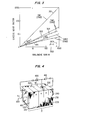
- the bandgap of the quaternary formed is shown as a function of , the liquid atomic fraction of Ga.
- the curves in FIG. 5 represent the liquidus and solidus data for the growth process.
- the smooth curves drawn through the vs. points, where and are the liquid atomic fractions of As and Ga respectively, are the loci of liquid compositions giving lattice-matched growth by this method.
- the curve in FIG. 7, together with the curves of FIG. 5 enables one to design the liquid solution necessary to grow any lattice matched In l-x Ga x As y P l-y composition at any wavelength in the range 0.92 ⁇ 1.65im.
- Electrical contacts may be made to n and p layers by electroplating with Sn-Ni-Au and Au respectively.
- the substrates of the devices grown according to an embodiment of the present invention may serve as a window layer for the incident radiation as is shown with substrate layer 410 in FIG. 4.
- use of an InP substrate causes the short wavelength limit of the device to be near 0.9um due to the absorption edge in the InP, i.e., radiation having ⁇ 0.95 ⁇ m is absorbed in thick substrate windows.
- the InP window layer may be replaced by a lattice-matched In l-x Ga x As y P l-y layer in order that the short wavelength response limit of these devices may be compositionally tuned in the same manner as the long wavelength response.
- These substrates may also have antireflection dielectric interference coatings placed on them to enhance the reception of radiation by the device. These coatings are well known in the art and may even be used where the incident radiation enters the device directly into a first layer of the sequence of layers.
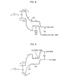
- FIG. 8 shows the energy level structure of a 2- stage pn-pn device constructed according to the embodiment shown in FIG. 4 where floating n layer 220 in FIG. 4, i.e., that layer having no applied bias voltage, is doped so lightly that it is fully depleted under normal operating conditions. This means that all residual background electrons are swept out of region 502 in FIG. 8 by the applied voltage and the electric field region of heterojunction 300 extends throughout region 502.
- This device should have a faster response time than devices fabricated with an undepleted floating n-layer. The reason for this is because the response time of devices having an undepleted floating n-layer is affected by the manner in which the forward biased np heterojunction, junction 301 in FIG.
- np heterojunction 301 With an undepleted floating n-layer, np heterojunction 301 does not allow residual electrons to flow out of n layer 220 in FIG. 4 until it has been able to adjust itself to allow injected electrons to flow across np heterojunction 301 to prevent n-layer 220 from charging. In the device having a fully depleted n-layer 220 no such self-adjustment of np heterojunction 301 is required.
- FIG. 9 shows the energy level structure of a 2-stage np-np device where region 431 corresponds to a floating p layer which is doped so lightly that it is fully depleted under normal operating conditions.
- the method of operation of this device is a mirror of the method of operation of a 2-stage pn-pn which has been described hereinabove.
- Region 432 becomes an electron trap for this device and is analogous to the hole trap formed for the pn-pn device shown as region 503 in FIG. 8.
Landscapes
- Light Receiving Elements (AREA)
- Liquid Deposition Of Substances Of Which Semiconductor Devices Are Composed (AREA)
- Solid State Image Pick-Up Elements (AREA)
Applications Claiming Priority (2)
| Application Number | Priority Date | Filing Date | Title |
|---|---|---|---|
| US64040 | 1979-08-06 | ||
| US06/064,040 US4250516A (en) | 1979-08-06 | 1979-08-06 | Multistage avalanche photodetector |
Publications (2)
| Publication Number | Publication Date |
|---|---|
| EP0023723A2 true EP0023723A2 (de) | 1981-02-11 |
| EP0023723A3 EP0023723A3 (de) | 1982-03-31 |
Family
ID=22053169
Family Applications (1)
| Application Number | Title | Priority Date | Filing Date |
|---|---|---|---|
| EP80104611A Withdrawn EP0023723A3 (de) | 1979-08-06 | 1980-08-06 | Mehrstufiger Avalanche-Fotodetektor |
Country Status (5)
| Country | Link |
|---|---|
| US (1) | US4250516A (de) |
| EP (1) | EP0023723A3 (de) |
| JP (1) | JPS56500990A (de) |
| ES (1) | ES8104640A1 (de) |
| WO (1) | WO1981000488A1 (de) |
Cited By (4)
| Publication number | Priority date | Publication date | Assignee | Title |
|---|---|---|---|---|
| EP0087299A3 (en) * | 1982-02-23 | 1984-09-05 | Western Electric Company, Incorporated | Multilayer avalanche photodetector |
| EP0108561A3 (en) * | 1982-11-08 | 1985-12-04 | Fujitsu Limited | Semiconductor device for receiving light and providing an electrical signal |
| EP0127724A3 (en) * | 1983-06-02 | 1986-08-06 | International Business Machines Corporation | Photodetector |
| EP0274940A1 (de) * | 1986-12-12 | 1988-07-20 | Thomson-Csf | Anordnung mit Lawinenmultiplikation von Ladungsträgern und Anwendung für Photodetektoren, Photokathoden und Infrarot-Bildaufnahmeeinrichtungen |
Families Citing this family (10)
| Publication number | Priority date | Publication date | Assignee | Title |
|---|---|---|---|---|
| JPS56165473A (en) * | 1980-05-24 | 1981-12-19 | Semiconductor Res Found | Semiconductor pickup device |
| US4486765A (en) * | 1981-12-07 | 1984-12-04 | At&T Bell Laboratories | Avalanche photodetector including means for separating electrons and holes |
| US4620214A (en) * | 1983-12-02 | 1986-10-28 | California Institute Of Technology | Multiple quantum-well infrared detector |
| GB8417303D0 (en) * | 1984-07-06 | 1984-08-08 | Secr Defence | Infra-red detector |
| FR2583577B1 (fr) * | 1985-06-18 | 1987-08-07 | Thomson Csf | Procede de realisation d'un dispositif photodetecteur semi-conducteur a avalanche et dispositif ainsi realise |
| US6534783B1 (en) * | 1989-12-27 | 2003-03-18 | Raytheon Company | Stacked multiple quantum well superlattice infrared detector |
| US6369436B1 (en) * | 2000-05-22 | 2002-04-09 | Boris Gilman | Semiconductor wavelength demultiplexer |
| US8279411B2 (en) * | 2008-08-27 | 2012-10-02 | The Boeing Company | Systems and methods for reducing crosstalk in an avalanche photodiode detector array |
| US9395182B1 (en) | 2011-03-03 | 2016-07-19 | The Boeing Company | Methods and systems for reducing crosstalk in avalanche photodiode detector arrays |
| DE102017011643B4 (de) * | 2017-12-15 | 2020-05-14 | Azur Space Solar Power Gmbh | Optische Spannungsquelle |
Family Cites Families (11)
| Publication number | Priority date | Publication date | Assignee | Title |
|---|---|---|---|---|
| US3982261A (en) * | 1972-09-22 | 1976-09-21 | Varian Associates | Epitaxial indium-gallium-arsenide phosphide layer on lattice-matched indium-phosphide substrate and devices |
| US4206002A (en) * | 1976-10-19 | 1980-06-03 | University Of Pittsburgh | Graded band gap multi-junction solar energy cell |
| US4103312A (en) * | 1977-06-09 | 1978-07-25 | International Business Machines Corporation | Semiconductor memory devices |
| US4110778A (en) * | 1977-06-21 | 1978-08-29 | The United States Of America As Represented By The Secretary Of The Air Force | Narrow-band inverted homo-heterojunction avalanche photodiode |
| FR2399740A1 (fr) * | 1977-08-02 | 1979-03-02 | Thomson Csf | Diode a avalanche a hetero-jonction, et oscillateur en mode dit " a temps de transit " utilisant une telle diode |
| US4127862A (en) * | 1977-09-06 | 1978-11-28 | Bell Telephone Laboratories, Incorporated | Integrated optical detectors |
| FR2408915A1 (fr) * | 1977-11-10 | 1979-06-08 | Thomson Csf | Photodiode a heterojonction, fonctionnant en avalanche sous une faible tension de polarisation |
| US4179702A (en) * | 1978-03-09 | 1979-12-18 | Research Triangle Institute | Cascade solar cells |
| US4163237A (en) * | 1978-04-24 | 1979-07-31 | Bell Telephone Laboratories, Incorporated | High mobility multilayered heterojunction devices employing modulated doping |
| US4203124A (en) * | 1978-10-06 | 1980-05-13 | Bell Telephone Laboratories, Incorporated | Low noise multistage avalanche photodetector |
| US4213138A (en) * | 1978-12-14 | 1980-07-15 | Bell Telephone Laboratories, Incorporated | Demultiplexing photodetector |
-
1979
- 1979-08-06 US US06/064,040 patent/US4250516A/en not_active Expired - Lifetime
-
1980
- 1980-07-24 JP JP50191480A patent/JPS56500990A/ja active Pending
- 1980-07-24 WO PCT/US1980/000921 patent/WO1981000488A1/en not_active Ceased
- 1980-08-05 ES ES494006A patent/ES8104640A1/es not_active Expired
- 1980-08-06 EP EP80104611A patent/EP0023723A3/de not_active Withdrawn
Cited By (7)
| Publication number | Priority date | Publication date | Assignee | Title |
|---|---|---|---|---|
| EP0087299A3 (en) * | 1982-02-23 | 1984-09-05 | Western Electric Company, Incorporated | Multilayer avalanche photodetector |
| EP0108561A3 (en) * | 1982-11-08 | 1985-12-04 | Fujitsu Limited | Semiconductor device for receiving light and providing an electrical signal |
| US4701773A (en) * | 1982-11-08 | 1987-10-20 | Fujitsu Limited | Semiconductor device for receiving light |
| EP0127724A3 (en) * | 1983-06-02 | 1986-08-06 | International Business Machines Corporation | Photodetector |
| EP0274940A1 (de) * | 1986-12-12 | 1988-07-20 | Thomson-Csf | Anordnung mit Lawinenmultiplikation von Ladungsträgern und Anwendung für Photodetektoren, Photokathoden und Infrarot-Bildaufnahmeeinrichtungen |
| FR2612334A1 (fr) * | 1986-12-12 | 1988-09-16 | Thomson Csf | Dispositif de multiplication de porteurs de charge par un phenomene d'avalanche et son application aux photodetecteurs, aux photocathodes, et aux visionneurs infrarouges |
| US4907042A (en) * | 1986-12-12 | 1990-03-06 | Thomson-Csf | Device for the multiplication of charge carriers by an avalanche phenomenon and application of the said device to photosensors, photocathodes and infrared viewing devices |
Also Published As
| Publication number | Publication date |
|---|---|
| ES494006A0 (es) | 1981-04-16 |
| US4250516A (en) | 1981-02-10 |
| ES8104640A1 (es) | 1981-04-16 |
| EP0023723A3 (de) | 1982-03-31 |
| JPS56500990A (de) | 1981-07-16 |
| WO1981000488A1 (en) | 1981-02-19 |
Similar Documents
| Publication | Publication Date | Title |
|---|---|---|
| US5371399A (en) | Compound semiconductor having metallic inclusions and devices fabricated therefrom | |
| US10032950B2 (en) | AllnAsSb avalanche photodiode and related method thereof | |
| US4476477A (en) | Graded bandgap multilayer avalanche photodetector with energy step backs | |
| US4250516A (en) | Multistage avalanche photodetector | |
| US6326654B1 (en) | Hybrid ultraviolet detector | |
| US4203124A (en) | Low noise multistage avalanche photodetector | |
| US20250204059A1 (en) | Semiconductor light-receiving device and method for manufacturing same | |
| Forrest et al. | Performance of In 0.53 Ga 0.47 As/InP avalanche photodiodes | |
| US4390889A (en) | Photodiode having an InGaAs layer with an adjacent InGaAsP p-n junction | |
| Lee | Photodetectors | |
| Stillman et al. | Long-wavelength (1.3-to 1.6-µm) detectors for fiber-optical communications | |
| US4631566A (en) | Long wavelength avalanche photodetector | |
| US4473835A (en) | Long wavelength avalanche photodetector | |
| US4587544A (en) | Avalanche photodetector | |
| Diadiuk et al. | Low dark-current, high gain GaInAs/InP avalanche photodetectors | |
| US4561007A (en) | Double mesa avalanche photodetector | |
| Kagawa et al. | InGaAs/InAlAs superlattice avalanche photodiode with a separated photoabsorption layer | |
| US4729004A (en) | Semiconductor photo device | |
| Becla et al. | Long wavelength HgMnTe avalanche photodiodes | |
| Law et al. | State‐of‐the‐art performance of GaAlAs/GaAs avalanche photodiodes | |
| US5115294A (en) | Optoelectronic integrated circuit | |
| EP0150564A2 (de) | Elektronische Vorrichtung mit einem Heteroübergang | |
| Budianu et al. | Heterostructures on InP substrate for high-speed detection devices over a large spectral range (0.8–1.6 μm) | |
| Piotrowski et al. | Optimisation of InGaAs infrared photovoltaic detectors | |
| Ban et al. | Characterization of process-induced defects in 2.6-um InGaAs photodiodes |
Legal Events
| Date | Code | Title | Description |
|---|---|---|---|
| PUAI | Public reference made under article 153(3) epc to a published international application that has entered the european phase |
Free format text: ORIGINAL CODE: 0009012 |
|
| AK | Designated contracting states |
Designated state(s): BE CH DE FR GB IT LI NL SE |
|
| 17P | Request for examination filed |
Effective date: 19811030 |
|
| PUAL | Search report despatched |
Free format text: ORIGINAL CODE: 0009013 |
|
| AK | Designated contracting states |
Designated state(s): BE CH DE FR GB IT LI NL SE |
|
| STAA | Information on the status of an ep patent application or granted ep patent |
Free format text: STATUS: THE APPLICATION HAS BEEN WITHDRAWN |
|
| 18W | Application withdrawn |
Withdrawal date: 19831111 |
|
| RIN1 | Information on inventor provided before grant (corrected) |
Inventor name: WORLOCK, JOHN MATHEW |