EP0023864A1 - Handbetätigte Führungsvorrichtung, insbesondere Handgriff zum Führen der Bewegungen eines angetriebenen Werkzeuges - Google Patents
Handbetätigte Führungsvorrichtung, insbesondere Handgriff zum Führen der Bewegungen eines angetriebenen Werkzeuges Download PDFInfo
- Publication number
- EP0023864A1 EP0023864A1 EP80401124A EP80401124A EP0023864A1 EP 0023864 A1 EP0023864 A1 EP 0023864A1 EP 80401124 A EP80401124 A EP 80401124A EP 80401124 A EP80401124 A EP 80401124A EP 0023864 A1 EP0023864 A1 EP 0023864A1
- Authority
- EP
- European Patent Office
- Prior art keywords
- membrane
- arm
- handle
- arms
- housing
- Prior art date
- Legal status (The legal status is an assumption and is not a legal conclusion. Google has not performed a legal analysis and makes no representation as to the accuracy of the status listed.)
- Granted
Links
- 239000012528 membrane Substances 0.000 claims description 59
- 230000003247 decreasing effect Effects 0.000 claims description 3
- 238000010422 painting Methods 0.000 description 9
- 210000000245 forearm Anatomy 0.000 description 6
- 230000000694 effects Effects 0.000 description 5
- 239000003973 paint Substances 0.000 description 3
- 239000007921 spray Substances 0.000 description 3
- 240000008042 Zea mays Species 0.000 description 2
- 229940082150 encore Drugs 0.000 description 2
- 239000000463 material Substances 0.000 description 2
- 241001080024 Telles Species 0.000 description 1
- 238000005452 bending Methods 0.000 description 1
- 239000004020 conductor Substances 0.000 description 1
- 238000010586 diagram Methods 0.000 description 1
- 238000006073 displacement reaction Methods 0.000 description 1
- 238000005553 drilling Methods 0.000 description 1
- 239000000835 fiber Substances 0.000 description 1
- 239000010985 leather Substances 0.000 description 1
- 238000000926 separation method Methods 0.000 description 1
Images

Classifications
-
- B—PERFORMING OPERATIONS; TRANSPORTING
- B25—HAND TOOLS; PORTABLE POWER-DRIVEN TOOLS; MANIPULATORS
- B25J—MANIPULATORS; CHAMBERS PROVIDED WITH MANIPULATION DEVICES
- B25J13/00—Controls for manipulators
- B25J13/02—Hand grip control means
-
- G—PHYSICS
- G01—MEASURING; TESTING
- G01L—MEASURING FORCE, STRESS, TORQUE, WORK, MECHANICAL POWER, MECHANICAL EFFICIENCY, OR FLUID PRESSURE
- G01L5/00—Apparatus for, or methods of, measuring force, work, mechanical power, or torque, specially adapted for specific purposes
- G01L5/16—Apparatus for, or methods of, measuring force, work, mechanical power, or torque, specially adapted for specific purposes for measuring several components of force
- G01L5/161—Apparatus for, or methods of, measuring force, work, mechanical power, or torque, specially adapted for specific purposes for measuring several components of force using variations in ohmic resistance
- G01L5/1627—Apparatus for, or methods of, measuring force, work, mechanical power, or torque, specially adapted for specific purposes for measuring several components of force using variations in ohmic resistance of strain gauges
-
- G—PHYSICS
- G01—MEASURING; TESTING
- G01L—MEASURING FORCE, STRESS, TORQUE, WORK, MECHANICAL POWER, MECHANICAL EFFICIENCY, OR FLUID PRESSURE
- G01L5/00—Apparatus for, or methods of, measuring force, work, mechanical power, or torque, specially adapted for specific purposes
- G01L5/22—Apparatus for, or methods of, measuring force, work, mechanical power, or torque, specially adapted for specific purposes for measuring the force applied to control members, e.g. control members of vehicles, triggers
- G01L5/223—Apparatus for, or methods of, measuring force, work, mechanical power, or torque, specially adapted for specific purposes for measuring the force applied to control members, e.g. control members of vehicles, triggers to joystick controls
-
- G—PHYSICS
- G05—CONTROLLING; REGULATING
- G05G—CONTROL DEVICES OR SYSTEMS INSOFAR AS CHARACTERISED BY MECHANICAL FEATURES ONLY
- G05G9/00—Manually-actuated control mechanisms provided with one single controlling member co-operating with two or more controlled members, e.g. selectively, simultaneously
- G05G9/02—Manually-actuated control mechanisms provided with one single controlling member co-operating with two or more controlled members, e.g. selectively, simultaneously the controlling member being movable in different independent ways, movement in each individual way actuating one controlled member only
- G05G9/04—Manually-actuated control mechanisms provided with one single controlling member co-operating with two or more controlled members, e.g. selectively, simultaneously the controlling member being movable in different independent ways, movement in each individual way actuating one controlled member only in which movement in two or more ways can occur simultaneously
- G05G9/047—Manually-actuated control mechanisms provided with one single controlling member co-operating with two or more controlled members, e.g. selectively, simultaneously the controlling member being movable in different independent ways, movement in each individual way actuating one controlled member only in which movement in two or more ways can occur simultaneously the controlling member being movable by hand about orthogonal axes, e.g. joysticks
- G05G2009/04703—Mounting of controlling member
- G05G2009/04707—Mounting of controlling member with ball joint
-
- G—PHYSICS
- G05—CONTROLLING; REGULATING
- G05G—CONTROL DEVICES OR SYSTEMS INSOFAR AS CHARACTERISED BY MECHANICAL FEATURES ONLY
- G05G9/00—Manually-actuated control mechanisms provided with one single controlling member co-operating with two or more controlled members, e.g. selectively, simultaneously
- G05G9/02—Manually-actuated control mechanisms provided with one single controlling member co-operating with two or more controlled members, e.g. selectively, simultaneously the controlling member being movable in different independent ways, movement in each individual way actuating one controlled member only
- G05G9/04—Manually-actuated control mechanisms provided with one single controlling member co-operating with two or more controlled members, e.g. selectively, simultaneously the controlling member being movable in different independent ways, movement in each individual way actuating one controlled member only in which movement in two or more ways can occur simultaneously
- G05G9/047—Manually-actuated control mechanisms provided with one single controlling member co-operating with two or more controlled members, e.g. selectively, simultaneously the controlling member being movable in different independent ways, movement in each individual way actuating one controlled member only in which movement in two or more ways can occur simultaneously the controlling member being movable by hand about orthogonal axes, e.g. joysticks
- G05G2009/0474—Manually-actuated control mechanisms provided with one single controlling member co-operating with two or more controlled members, e.g. selectively, simultaneously the controlling member being movable in different independent ways, movement in each individual way actuating one controlled member only in which movement in two or more ways can occur simultaneously the controlling member being movable by hand about orthogonal axes, e.g. joysticks characterised by means converting mechanical movement into electric signals
- G05G2009/04762—Force transducer, e.g. strain gauge
-
- H—ELECTRICITY
- H01—ELECTRIC ELEMENTS
- H01H—ELECTRIC SWITCHES; RELAYS; SELECTORS; EMERGENCY PROTECTIVE DEVICES
- H01H2239/00—Miscellaneous
- H01H2239/052—Strain gauge
-
- Y—GENERAL TAGGING OF NEW TECHNOLOGICAL DEVELOPMENTS; GENERAL TAGGING OF CROSS-SECTIONAL TECHNOLOGIES SPANNING OVER SEVERAL SECTIONS OF THE IPC; TECHNICAL SUBJECTS COVERED BY FORMER USPC CROSS-REFERENCE ART COLLECTIONS [XRACs] AND DIGESTS
- Y10—TECHNICAL SUBJECTS COVERED BY FORMER USPC
- Y10T—TECHNICAL SUBJECTS COVERED BY FORMER US CLASSIFICATION
- Y10T74/00—Machine element or mechanism
- Y10T74/20—Control lever and linkage systems
- Y10T74/20012—Multiple controlled elements
- Y10T74/20201—Control moves in two planes
Definitions
- the present invention relates to a manual control device, in particular a handle for manually controlling the movements, in three perpendicular directions, of a motorized member.
- French patent application No. 78 20513 which the Applicant filed on July 10, 1978 for "Manipulator, in particular automatic painting machine, capable of learning", described a device with handle for manually controlling movements, in three directions perpendicular, of a manipulator arm, in particular of a painting automaton.
- This manual control device comprises a deformable membrane in the shape of a cross, the central part of which is subject to the handle, and each of the arms of which carries a pair of strain gauges, fixed respectively on the two faces of the brasa
- the present invention relates to various improvements to the manual control device described in the French patent application mentioned above, these improvements being moreover applicable to all manual control devices of the type indicated above, whether or not they are associated with manipulators or to automata.
- the manual control device also comprises a deformable membrane in the form of a cross, the central part of which is subject to the control handle, and each of the arms of which carries a pair of strain gauges, fixed respectively on the two faces of the arms ; it is further characterized in that the end of each of the arms of the membrane is coupled to an element integral with the member to be moved, by means of a bearing, arranged so as to allow the corresponding arm of the membrane to rotate without torsion around its longitudinal axis, when the handle undergoes a force in the direction perpendicular to this axis.
- any force, or component of a force applied to the control handle in a direction parallel to the axis of two of the arms of the cross-shaped membrane has the effect of deforming exclusively these two arms, while the other two arms, perpendicular to the direction of the applied force, rotate without being deformed, in particular without being twisted; the force, or the component of the applied force is therefore captured only by the strain gauges fixed to the arms parallel to the direction of this force, while the strain gauges fixed on the two other arms, perpendicular to the force, do not are hardly influenced by it.
- the part of each arm of the membrane which is between its central part and the bearing associated with the end of this arm, is at least partially in shape trapezoid, decreasing in width in the centrifugal direction.
- This arrangement has the effect of regularizing the longitudinal curvature that each arm of the membrane takes when the control handle undergoes a force in the longitudinal direction. of this arm.
- each arm of the membrane is mounted in the corresponding bearing preferably so as to be able to slide freely, relative to said bearing, in the longitudinal direction of this arm.
- This arrangement facilitates the deformation, in particular the longitudinal curvature, of each arm of the membrane when the control handle undergoes a force in the longitudinal direction of this arm.
- the manual control device is preferably arranged as follows: the pairs of strain gauges fixed respectively to the different arms, a, b, c and d, of the diaphragm, are electrically mounted in series between the terminals of an electric voltage source, so that the longitudinal curvature that takes up each arm of the diaphragm when the control handle undergoes a force in the longitudinal direction of that arm , at the common point of the corresponding pair of gauges, an electrical voltage, A, B, C or D; on the other hand, known electrical circuits are provided to deduce electrical signals therefrom, respectively proportional to the forces undergone by the control handle in the three perpendicular directions:
- a gripping button for example hemispherical
- a ball joint can be coupled, by means of a ball joint, to the free end of the control handle or of its rod.
- the torques that he can apply, even involuntarily, to said grip button when he moves the handle are not transmitted to the rod of the latter, due to the interposition of the ball joint, so that the rod of the control handle receives only the components of translation of the force applied to the grip button, these components being the only ones which must be captured by the strain gauges, fixed to the different arms of the deformable membrane.
- the gripping button can advantageously be connected at the bottom of the housing by a flexible cuff, preferably in the form of a bellows, which surrounds without contact the part of the rod of the control handle, which emerges freely from said bottom.
- the handle proper, which the operator grasps is then in fact formed by the grip button and the flexible cuff which connects it to the bottom of the housing, where the deformable membrane is housed.
- the automatic painting machine which is illustrated diagrammatically in FIG. 1 is for example of the type described in patent application No. 78 20513, already previously mentioned. It comprises a housing 1, on which a turret 2 is mounted so as to be able to pivot around a vertical axis O, under the action of a motor housed in the housing 1.
- An arm 3 has its lower end articulated on the turret 2 so as to be able to pivot about a horizontal axis P.
- a forearm 4 On the upper end of the arm 3, a forearm 4 has one of its ends articulated so as to be able to pivot around a horizontal axis Q.
- Two hydraulic cylinders, 5 and 6, are mounted so as to respectively control the pivoting of the arms 3 and 4 around their respective articulations.
- the free end of the forearm 4 supports a paint spray gun 9.
- a tubular appendage 11 is detached from the forearm 4, at a small distance from its end carrying the spray gun 9; this tubular appendage 11 is shaped so as to support, at a certain distance from the forearm 4, a manual control handle 12; the assembly is arranged in such a way that the same operator can grasp, with his right hand, the butt of the paint gun 9 and with his left hand, the manual control handle 12.
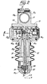
- a housing 13 is interposed between the control handle 12 and the tubular appendage 11, around which two jaws, 13a and 13b, integral with the upper part of said housing 13, are tightened by a screw 14.
- a deformable membrane in the shape of a cross, 15, the four arms of which will be designated below by a, b, c and d.
- the end of each of the arms a to d of the membrane 15 is coupled to one of the walls of the housing 13, by means of a bearing 16a, 16b, 16c or 16d, which is mounted in the corresponding side wall of the housing 13.
- each bearing as 16a is housed in the bore central of a plug 17a, the body of which is engaged in a corresponding orifice in the wall of the housing 13, to which a flange of said plug 17a is fixed by screws such as 18a.
- the part of each arm, such as a, of the membrane 15, which is included between its central part m and the bearing, 16a, associated with the end of this arm, a is partially in the form of trapezoid, width 1 decreasing in the centrifugal direction.
- Each bearing such as 16a comprises at least one ball bearing 19a, the external raceway 20a of which is forcibly engaged in the central bore of the plug 17a, while its internal raceway 21a is immobilized by a screw 22a and a washer 23a on the cylindrical barrel 24a of a part engaged in the central bore of the plug 17a; towards the outside of the central bore of the plug 17a, the cylindrical barrel 24a is extended by a substantially cylindrical part, 25a, which is integral therewith, and which comprises a slot arranged so as to receive the free end of the arm a of the membrane deformable 15; this free end of the arm a is preferably expanded so that it can be tightened in the slot of the part 25a by two screws 26a.
- the external raceway 20a of which is forcibly engaged in the central bore of the plug 17a
- its internal raceway 21a is immobilized by a screw 22a and a washer 23a on the cylindrical barrel 24a of a part engaged in the central bore of the plug 17a
- the cylindrical barrel 24a
- the raceways 20a and 21a of the ball bearing 19a are arranged so as to allow limited axial movement of the inner raceway 21a relative to the outer raceway 20a; as the end of the arm a of the deformable membrane 15 is integral with the parts 25a, 24a and 21a, this arrangement allows the end of each arm, such as a, of the membrane 15, to slide freely in the longitudinal direction e (of said arm a, relative to the elements of the bearing 16a which are integral with the wall of the housing 13w
- the central bore of the plug 17a is finally normally closed by a cover 29a, which is fixed to it by screws such as 3oa.
- This arrangement has the advantage of making it possible to dismantle each of the bearings such as 16a, from the outside
- the central part, m, of the deformable membrane 15, is on the other hand subject to the upper end of a rod 31, which freely crosses the bottom of the housing 13 by a bore 13c of this bottom; the outer mouth of this bore 13c is surrounded, outside the housing 13, and below its bottom, by a tubular endpiece 13d, which surrounds without contact the upper part of the rod 31.
- the upper end of this rod 31 also has an overhanging flange 31a, on which the central part m of the deformable membrane 15 is tightened by a part 32 and screws such as 32a, so as to ensure that said central part m is embedded on the upper end of the rod 31.
- the upper end, 31b, of this rod 31 also passes through a central bore of the membrane 15 and extends above the part 32, as visible in FIG. 2, direction of an axial stop 33, arranged in the upper wall of the housing 13.
- a gripping button, hemispherical, 34 is coupled, via a ball joint 35, to the free end, lower, 31c, of the rod 31.
- this bou hemispherical grip tone 34 is connected to the bottom of the housing 13, and in particular to the upper part of the endpiece 13d which extends it downwards, by a flexible cuff 36, in the form of a bellows, for example of leather, which surrounds without contact the part of the rod 31 which is external to the tubular end piece 13d of the housing 13.
- the manual control handle 12, which the operator grasps is then essentially constituted by the grip button 34, possibly the lower part of the flexible cuff 36, which is subject to said grip button.
- a spring 37 is inserted between the respective bottoms of two coaxial recesses, one in the grip button 34, and the other in the lower end, 31c, of the rod 31, so as to compensate for the weight of said rod 31.
- pairs of strain gauges such as Jal and Ja2 are fixed, for example glued, respectively on the two faces of each arm, such as a, of the deformable membrane 15.
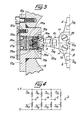
- these pairs strain gauges fixed respectively to the different arms a, b, c and d of the membrane 15 are electrically connected in series, as illustrated in FIG. 4, between the terminals of a source of electric voltage, in particular of a source of DC voltage + V, and electrical signals A, B, C and D are taken respectively from the common points of the different pairs of gauges, such as Jal and Ja2, connected in series.
- the automatic control device 39 is on the other hand connected to a memory 42 of a known type, and it further comprises a microprocessor, 43, an interface 40b, to which are electrically connected, by a cable 38b, displacement sensors around the three axes 0, PetQ, as well as an interface 40c, which transmits by a cable 38c control signals to the respective motors of the turret 2 and of the arms 3 and 4 (the jacks 5 and 6).
- the microprocessor 43 is programmed so that the aforementioned motors apply forces to the different movable members 2, 3 and 4, the result of which is parallel, in the same direction and proportional to the force applied manually by the operator to the control handle 12, of components X, Y and Z, the coefficient of proportionality being chosen to be significantly greater than unity, so as to obtain a multiplication of said manual effort, sufficient to overcome the inertia and the internal friction of the automaton.
- the successive values of the position signals of the movable members 2, 3, 4 received by the interface 40b are recorded progressively in the memory 42.
- the content of the memory 42 can be read, the memory signals, processed by the microprocessor 43, being transmitted successively by the interface 40c and the cable 38c, to the respective motors of the mobile members 2, 3, 4 , so that the end of the forearm 4, which carries the paint spray gun 9, automatically performs the same movements in space as during the previous learning phase, where the operator controlled these movements in acting on the handle 12.
- the manual control device which has just been described is not exclusively intended for the manual control of the movements of a painting automaton; it can be used to control the movements, in three perpendicular directions, of an arm of an automaton or any manipulator, or even, more generally, of any motorized member.
- the present invention is also not limited to the form previously described embodiment of the manual control device; it encompasses all of its variants.
- the extensometric gauges Jal to Jd2 can be replaced by flat deformation or stress sensors, of another type, suitable.
- the grip button 34 and its connection sleeve 36 are optional; in their absence, however, the torques that the operator possibly applies to the rod 31, to which the control handle 12 is reduced, produce the specific deformations of the membrane 15, so that the exploitation of the electrical signals produced by flat strain or strain sensors, notably Jal to Jd2 strain gauges, may require relatively more complicated electronic circuits.
- the mounting of the deformable membrane 15 in a housing 13, as well as the production of the latter, are optional materials. The same applies to the electrical mounting of the various strain gauges, Jal to Jd2, which is illustrated in FIG. 4.
- the ball bearings, such as 16a can be replaced by equivalent bearings, of another known type; instead of providing a possibility of axial sliding between the two raceways, 20a and 21a, of each ball bearing 16a, or of each equivalent bearing, it is also possible to provide a possibility of free sliding of the free end of the corresponding arm, a, of the membrane 15, with respect to the rotating part of the bearing.
- the shape of each arm of the deformable membrane 15 is optional material.
Landscapes
- Physics & Mathematics (AREA)
- General Physics & Mathematics (AREA)
- Engineering & Computer Science (AREA)
- Automation & Control Theory (AREA)
- Robotics (AREA)
- Mechanical Engineering (AREA)
- Manipulator (AREA)
- Mechanical Control Devices (AREA)
- Spinning Or Twisting Of Yarns (AREA)
- Reciprocating Pumps (AREA)
- Steering Controls (AREA)
- Electric Propulsion And Braking For Vehicles (AREA)
- Finish Polishing, Edge Sharpening, And Grinding By Specific Grinding Devices (AREA)
- Preliminary Treatment Of Fibers (AREA)
- Catching Or Destruction (AREA)
Priority Applications (1)
| Application Number | Priority Date | Filing Date | Title |
|---|---|---|---|
| AT80401124T ATE4032T1 (de) | 1979-08-02 | 1980-07-30 | Handbetaetigte fuehrungsvorrichtung, insbesondere handgriff zum fuehren der bewegungen eines angetriebenen werkzeuges. |
Applications Claiming Priority (2)
| Application Number | Priority Date | Filing Date | Title |
|---|---|---|---|
| FR7919844 | 1979-08-02 | ||
| FR7919844A FR2462743A1 (fr) | 1979-08-02 | 1979-08-02 | Dispositif de commande manuelle, notamment poignee pour commander les deplacements d'un organe motorise |
Publications (2)
| Publication Number | Publication Date |
|---|---|
| EP0023864A1 true EP0023864A1 (de) | 1981-02-11 |
| EP0023864B1 EP0023864B1 (de) | 1983-07-06 |
Family
ID=9228550
Family Applications (1)
| Application Number | Title | Priority Date | Filing Date |
|---|---|---|---|
| EP80401124A Expired EP0023864B1 (de) | 1979-08-02 | 1980-07-30 | Handbetätigte Führungsvorrichtung, insbesondere Handgriff zum Führen der Bewegungen eines angetriebenen Werkzeuges |
Country Status (6)
| Country | Link |
|---|---|
| US (1) | US4348634A (de) |
| EP (1) | EP0023864B1 (de) |
| AT (1) | ATE4032T1 (de) |
| DE (1) | DE3064035D1 (de) |
| ES (1) | ES493933A0 (de) |
| FR (1) | FR2462743A1 (de) |
Cited By (1)
| Publication number | Priority date | Publication date | Assignee | Title |
|---|---|---|---|---|
| EP0635858A1 (de) * | 1993-07-23 | 1995-01-25 | Sextant Avionique | Steuerknüppel |
Families Citing this family (26)
| Publication number | Priority date | Publication date | Assignee | Title |
|---|---|---|---|---|
| SE436231B (sv) * | 1980-07-04 | 1984-11-19 | Zettergren Ted Ab | Anordning vid flerlegesspak |
| US4519741A (en) * | 1982-01-04 | 1985-05-28 | Ormig S.P.A. | Mobile yard crane for handling containers |
| JPS58171279A (ja) * | 1982-03-31 | 1983-10-07 | 株式会社ダイヘン | 産業用ロボツト |
| SE436848B (sv) * | 1982-06-28 | 1985-01-28 | Asea Ab | Styrsystem for industrirobot |
| FR2545606B1 (fr) * | 1983-05-06 | 1985-09-13 | Hispano Suiza Sa | Capteur de torseur de forces |
| SE8305378L (sv) * | 1983-09-30 | 1985-03-31 | Asea Ab | Industrirobot |
| US4680577A (en) * | 1983-11-28 | 1987-07-14 | Tektronix, Inc. | Multipurpose cursor control keyswitch |
| AU3583084A (en) * | 1983-12-10 | 1985-06-13 | Aida Engineering Ltd. | Playback grinding robot |
| FR2590044B1 (fr) * | 1985-09-27 | 1988-01-29 | Applic Mach Motrices | Dispositif de commande electrique motorise |
| US4755100A (en) * | 1985-11-12 | 1988-07-05 | Clark Equipment Company | Operator control system |
| FR2592607B1 (fr) * | 1986-01-06 | 1988-04-08 | Outiperret Sa | Dispositif manipulateur multiplicateur d'efforts tridimensionnel. |
| US4949794A (en) * | 1988-05-31 | 1990-08-21 | Premier Industrial Corporation | Remotely controlled firefighting apparatus and control means |
| US6701296B1 (en) | 1988-10-14 | 2004-03-02 | James F. Kramer | Strain-sensing goniometers, systems, and recognition algorithms |
| US5047952A (en) * | 1988-10-14 | 1991-09-10 | The Board Of Trustee Of The Leland Stanford Junior University | Communication system for deaf, deaf-blind, or non-vocal individuals using instrumented glove |
| FR2658602B1 (fr) * | 1990-02-21 | 1994-01-28 | Joel Moreau | Dispositif de commande manuelle pour machines de mesure tridimensionnelle a deplacements motorises. |
| FR2659789B1 (fr) * | 1990-03-15 | 1996-09-27 | Sextant Avionique | Manipulateur a jauges de contrainte. |
| TW290666B (de) * | 1994-03-02 | 1996-11-11 | Alps Electric Co Ltd | |
| DE19630075A1 (de) * | 1996-07-26 | 1998-05-28 | Gerhard Dipl Ing Wergen | Mehrdimensional wirkende Handhabe |
| WO2000018548A1 (en) * | 1997-10-09 | 2000-04-06 | The New Zealand Meat Producers Board | Operator assisted robotic apparatus |
| WO2000014613A1 (en) * | 1998-09-08 | 2000-03-16 | Brown & Sharpe Manufacturing Company | Power assist manual coordinate measuring machine and method for using same |
| DE29919136U1 (de) * | 1999-10-30 | 2001-03-08 | Münnekehoff, Gerd, Dipl.-Ing., 42857 Remscheid | System zum Steuern der Bewegungen einer Lasthebevorrichtung |
| RU2226149C2 (ru) * | 2002-05-13 | 2004-03-27 | ОАО Уральский научно-технологический комплекс | Задающее устройство манипулятора |
| DE102004051504A1 (de) * | 2004-10-21 | 2006-05-18 | Zf Friedrichshafen Ag | Kraftmesssystem mit zumindest einem Kugelgelenk |
| WO2007121376A2 (en) * | 2006-04-17 | 2007-10-25 | Kci Licensing, Inc. | System and method for bed transport |
| RU2691807C1 (ru) * | 2018-01-09 | 2019-06-18 | Александр Андреевич Никитин | Гибкий исполнительный орган манипулятора |
| IT202200002306A1 (it) * | 2022-02-08 | 2023-08-08 | Idea Prototipi Srl | Organo di manovra rimovibile per il movimento di un dispositivo operatore automatico |
Citations (6)
| Publication number | Priority date | Publication date | Assignee | Title |
|---|---|---|---|---|
| FR2209099A1 (de) * | 1972-10-18 | 1974-06-28 | Saab Scania Ab | |
| FR2211137A5 (de) * | 1972-12-19 | 1974-07-12 | Sagem | |
| US3824674A (en) * | 1972-07-19 | 1974-07-23 | Hitachi Ltd | Automatic assembly control method and device therefor |
| GB1450788A (en) * | 1972-12-01 | 1976-09-29 | Hitachi Ltd | Automatic assembly apparatus for the assembly of one component into a second component |
| FR2369055A1 (fr) * | 1976-10-29 | 1978-05-26 | Creusot Loire | Dis |
| FR2435329A1 (fr) * | 1978-07-10 | 1980-04-04 | Ass Ouvriers Instr Precision | Manipulateur, en particulier automate de peinture, susceptible d'apprentissage |
Family Cites Families (3)
| Publication number | Priority date | Publication date | Assignee | Title |
|---|---|---|---|---|
| US3991618A (en) * | 1973-12-18 | 1976-11-16 | Maschinenfabrik Fahr Aktiengesellschaft | Sensor for automatic steering system for row-crop harvester |
| US3915015A (en) * | 1974-03-18 | 1975-10-28 | Stanford Research Inst | Strain gauge transducer system |
| CA1081342A (en) * | 1978-10-18 | 1980-07-08 | Atomic Energy Of Canada Limited - Energie Atomique Du Canada, Limitee | Three dimensional strain gage transducer |
-
1979
- 1979-08-02 FR FR7919844A patent/FR2462743A1/fr active Granted
-
1980
- 1980-07-30 EP EP80401124A patent/EP0023864B1/de not_active Expired
- 1980-07-30 US US06/173,454 patent/US4348634A/en not_active Expired - Lifetime
- 1980-07-30 AT AT80401124T patent/ATE4032T1/de not_active IP Right Cessation
- 1980-07-30 DE DE8080401124T patent/DE3064035D1/de not_active Expired
- 1980-08-01 ES ES493933A patent/ES493933A0/es active Granted
Patent Citations (8)
| Publication number | Priority date | Publication date | Assignee | Title |
|---|---|---|---|---|
| US3824674A (en) * | 1972-07-19 | 1974-07-23 | Hitachi Ltd | Automatic assembly control method and device therefor |
| FR2209099A1 (de) * | 1972-10-18 | 1974-06-28 | Saab Scania Ab | |
| CH561130A5 (de) * | 1972-10-18 | 1975-04-30 | Saab Scania Ab | |
| GB1408351A (en) * | 1972-10-18 | 1975-10-01 | Saab Scania Ab | Control stick |
| GB1450788A (en) * | 1972-12-01 | 1976-09-29 | Hitachi Ltd | Automatic assembly apparatus for the assembly of one component into a second component |
| FR2211137A5 (de) * | 1972-12-19 | 1974-07-12 | Sagem | |
| FR2369055A1 (fr) * | 1976-10-29 | 1978-05-26 | Creusot Loire | Dis |
| FR2435329A1 (fr) * | 1978-07-10 | 1980-04-04 | Ass Ouvriers Instr Precision | Manipulateur, en particulier automate de peinture, susceptible d'apprentissage |
Non-Patent Citations (1)
| Title |
|---|
| JAPAN INDUSTRIAL ROBOT ASSOCIATION, Proceedings of the 4th International Symposium on Industrial Robots, 19-21 Novembre 1974, pages 65-78 Tokyo, JP. J.L. NEVINS et D.E. WHITNEY: "Exploratory Research in Industrial Modular Assembly" * Figure 5; page 71, lignes 5-8; page 72, lignes 10-22 * * |
Cited By (2)
| Publication number | Priority date | Publication date | Assignee | Title |
|---|---|---|---|---|
| EP0635858A1 (de) * | 1993-07-23 | 1995-01-25 | Sextant Avionique | Steuerknüppel |
| FR2707911A1 (fr) * | 1993-07-23 | 1995-01-27 | Sextant Avionique | Manipulateur à actionnement multimode. |
Also Published As
| Publication number | Publication date |
|---|---|
| ES8103859A1 (es) | 1981-03-16 |
| ES493933A0 (es) | 1981-03-16 |
| US4348634A (en) | 1982-09-07 |
| ATE4032T1 (de) | 1983-07-15 |
| EP0023864B1 (de) | 1983-07-06 |
| DE3064035D1 (en) | 1983-08-11 |
| FR2462743B1 (de) | 1984-10-05 |
| FR2462743A1 (fr) | 1981-02-13 |
Similar Documents
| Publication | Publication Date | Title |
|---|---|---|
| EP0023864B1 (de) | Handbetätigte Führungsvorrichtung, insbesondere Handgriff zum Führen der Bewegungen eines angetriebenen Werkzeuges | |
| BE898154A (fr) | Manipuleur pour positionner des pièces à usiner ou d'autres charges. | |
| EP0143673A1 (de) | Mit mehreren Kontaktgreifflächen versehene Greifer | |
| WO2014009192A1 (fr) | Dispositif de transmission de mouvement a reducteur epicycloidal, reducteur epicycloidal et bras de manipulation | |
| EP0309329B1 (de) | Vorrichtung zum Orientieren eines Objektes um zwei Schwenkachsen | |
| FR2631868A1 (fr) | Dispositif et procede de vissage et de devissage d'un ecrou sur un element de liaison | |
| EP4076864B1 (de) | Roboterhand, die empfindlich auf kräfte in einer aquatischen umgebung reagiert | |
| EP0330551B1 (de) | Automatischer Objektgreifer | |
| FR2503012A1 (fr) | Articulation a trois axes pour robot, machine-outil ou similaire | |
| WO2005084894A1 (fr) | Bras de telemanipulation en deux parties. | |
| EP2054200B1 (de) | Werkzeug mit hilfsvorrichtung zur betätigung | |
| FR2877867A1 (fr) | Dispositif de prehension pour robot parallele | |
| EP1138434B1 (de) | Elektrisch betriebene Vorrichtung für einen Greifer | |
| EP0330548A1 (de) | Gewichtsausgleichsvorrichtung für den Arm eines Roboters oder dergleichen | |
| EP0085605B1 (de) | Greifvorrichtung mit Greifkraftmesssystem, versehen mit einer mehrere Freiheitsgrade aufweisenden gegliederten Struktur eingebaut zwischen seiner Kontaktplatte und seinem Halter | |
| EP0314564A1 (de) | Greifwerkzeug, besonders zum Fernbedienen von Kabelverbindungsstiften | |
| EP4608611A1 (de) | Gelenk mit drei freiheitsgraden mit kraftrückkopplung | |
| FR2707912A1 (fr) | Dispositif de préhension fixé au nez d'un robot pour saisir des pièces plates ou peu galbées de véhicule automobile. | |
| FR2519894A1 (fr) | Telemanipulateur telescopique du type maitre-esclave et ses moyens d'equilibrage | |
| EP1820079A1 (de) | Haptische schnittstelle mit kabeln | |
| FR2618202A1 (fr) | Dispositif de transmission de mouvement a deux niveaux de vitesse et de maintien d'un effort determine apres l'arret du mouvement. | |
| FR2677445A1 (fr) | Dispositif de reglage automatique de la position angulaire d'une roue d'un vehicule automobile, applique au reglage du parallelisme des roues. | |
| FR2599289A1 (fr) | Pince mecanique a trois mors destines en particulier a un robot. | |
| CA3236996A1 (fr) | Doigt et dispositif de prehension pour bras de robot, bras de robot equipe d'un tel dispositif | |
| FR2678193A1 (fr) | Robot de soudage par faisceau laser. |
Legal Events
| Date | Code | Title | Description |
|---|---|---|---|
| PUAI | Public reference made under article 153(3) epc to a published international application that has entered the european phase |
Free format text: ORIGINAL CODE: 0009012 |
|
| AK | Designated contracting states |
Designated state(s): AT BE CH DE GB IT LU NL SE |
|
| ITCL | It: translation for ep claims filed |
Representative=s name: STUDIO TORTA SOCIETA' SEMPLICE |
|
| TCAT | At: translation of patent claims filed | ||
| 17P | Request for examination filed |
Effective date: 19810803 |
|
| DET | De: translation of patent claims | ||
| ITF | It: translation for a ep patent filed | ||
| GRAA | (expected) grant |
Free format text: ORIGINAL CODE: 0009210 |
|
| AK | Designated contracting states |
Designated state(s): AT BE CH DE GB IT LI LU NL SE |
|
| REF | Corresponds to: |
Ref document number: 4032 Country of ref document: AT Date of ref document: 19830715 Kind code of ref document: T |
|
| PG25 | Lapsed in a contracting state [announced via postgrant information from national office to epo] |
Ref country code: LU Free format text: LAPSE BECAUSE OF NON-PAYMENT OF DUE FEES Effective date: 19830731 |
|
| REF | Corresponds to: |
Ref document number: 3064035 Country of ref document: DE Date of ref document: 19830811 |
|
| PGFP | Annual fee paid to national office [announced via postgrant information from national office to epo] |
Ref country code: LU Payment date: 19831019 Year of fee payment: 4 |
|
| PLBE | No opposition filed within time limit |
Free format text: ORIGINAL CODE: 0009261 |
|
| STAA | Information on the status of an ep patent application or granted ep patent |
Free format text: STATUS: NO OPPOSITION FILED WITHIN TIME LIMIT |
|
| PGFP | Annual fee paid to national office [announced via postgrant information from national office to epo] |
Ref country code: SE Payment date: 19840630 Year of fee payment: 5 Ref country code: BE Payment date: 19840630 Year of fee payment: 5 |
|
| 26N | No opposition filed | ||
| PGFP | Annual fee paid to national office [announced via postgrant information from national office to epo] |
Ref country code: AT Payment date: 19840720 Year of fee payment: 5 |
|
| PGFP | Annual fee paid to national office [announced via postgrant information from national office to epo] |
Ref country code: DE Payment date: 19840726 Year of fee payment: 5 |
|
| PGFP | Annual fee paid to national office [announced via postgrant information from national office to epo] |
Ref country code: NL Payment date: 19840731 Year of fee payment: 5 |
|
| PGFP | Annual fee paid to national office [announced via postgrant information from national office to epo] |
Ref country code: CH Payment date: 19840824 Year of fee payment: 5 |
|
| PG25 | Lapsed in a contracting state [announced via postgrant information from national office to epo] |
Ref country code: AT Effective date: 19850730 |
|
| PG25 | Lapsed in a contracting state [announced via postgrant information from national office to epo] |
Ref country code: SE Effective date: 19850731 Ref country code: LI Effective date: 19850731 Ref country code: CH Effective date: 19850731 Ref country code: BE Effective date: 19850731 |
|
| BERE | Be: lapsed |
Owner name: ASSOCIATION DES OUVRIERS EN INSTRUMENTS DE PRECIS Effective date: 19850731 |
|
| PG25 | Lapsed in a contracting state [announced via postgrant information from national office to epo] |
Ref country code: NL Effective date: 19860201 |
|
| GBPC | Gb: european patent ceased through non-payment of renewal fee | ||
| NLV4 | Nl: lapsed or anulled due to non-payment of the annual fee | ||
| REG | Reference to a national code |
Ref country code: CH Ref legal event code: PL |
|
| PG25 | Lapsed in a contracting state [announced via postgrant information from national office to epo] |
Ref country code: DE Effective date: 19860402 |
|
| PG25 | Lapsed in a contracting state [announced via postgrant information from national office to epo] |
Ref country code: GB Effective date: 19881118 |
|
| EUG | Se: european patent has lapsed |
Ref document number: 80401124.5 Effective date: 19860729 |