EP0024187A2 - System zum Einsammeln von Produkten, die auf die Oberfläche einer Wassermenge gestürzt wurden - Google Patents
System zum Einsammeln von Produkten, die auf die Oberfläche einer Wassermenge gestürzt wurden Download PDFInfo
- Publication number
- EP0024187A2 EP0024187A2 EP80302765A EP80302765A EP0024187A2 EP 0024187 A2 EP0024187 A2 EP 0024187A2 EP 80302765 A EP80302765 A EP 80302765A EP 80302765 A EP80302765 A EP 80302765A EP 0024187 A2 EP0024187 A2 EP 0024187A2
- Authority
- EP
- European Patent Office
- Prior art keywords
- tanker
- cages
- suction pumps
- suction
- opening
- Prior art date
- Legal status (The legal status is an assumption and is not a legal conclusion. Google has not performed a legal analysis and makes no representation as to the accuracy of the status listed.)
- Granted
Links
Images




Classifications
-
- E—FIXED CONSTRUCTIONS
- E02—HYDRAULIC ENGINEERING; FOUNDATIONS; SOIL SHIFTING
- E02B—HYDRAULIC ENGINEERING
- E02B15/00—Cleaning or keeping clear the surface of open water; Apparatus therefor
- E02B15/04—Devices for cleaning or keeping clear the surface of open water from oil or like floating materials by separating or removing these materials
- E02B15/046—Collection of oil using vessels, i.e. boats, barges
- E02B15/047—Collection of oil using vessels, i.e. boats, barges provided with an oil collecting boom arranged on at least one side of the hull
-
- E—FIXED CONSTRUCTIONS
- E02—HYDRAULIC ENGINEERING; FOUNDATIONS; SOIL SHIFTING
- E02B—HYDRAULIC ENGINEERING
- E02B15/00—Cleaning or keeping clear the surface of open water; Apparatus therefor
- E02B15/04—Devices for cleaning or keeping clear the surface of open water from oil or like floating materials by separating or removing these materials
- E02B15/10—Devices for removing the material from the surface
- E02B15/106—Overflow skimmers with suction heads; suction heads
-
- Y—GENERAL TAGGING OF NEW TECHNOLOGICAL DEVELOPMENTS; GENERAL TAGGING OF CROSS-SECTIONAL TECHNOLOGIES SPANNING OVER SEVERAL SECTIONS OF THE IPC; TECHNICAL SUBJECTS COVERED BY FORMER USPC CROSS-REFERENCE ART COLLECTIONS [XRACs] AND DIGESTS
- Y02—TECHNOLOGIES OR APPLICATIONS FOR MITIGATION OR ADAPTATION AGAINST CLIMATE CHANGE
- Y02A—TECHNOLOGIES FOR ADAPTATION TO CLIMATE CHANGE
- Y02A20/00—Water conservation; Efficient water supply; Efficient water use
- Y02A20/20—Controlling water pollution; Waste water treatment
- Y02A20/204—Keeping clear the surface of open water from oil spills
-
- Y—GENERAL TAGGING OF NEW TECHNOLOGICAL DEVELOPMENTS; GENERAL TAGGING OF CROSS-SECTIONAL TECHNOLOGIES SPANNING OVER SEVERAL SECTIONS OF THE IPC; TECHNICAL SUBJECTS COVERED BY FORMER USPC CROSS-REFERENCE ART COLLECTIONS [XRACs] AND DIGESTS
- Y10—TECHNICAL SUBJECTS COVERED BY FORMER USPC
- Y10S—TECHNICAL SUBJECTS COVERED BY FORMER USPC CROSS-REFERENCE ART COLLECTIONS [XRACs] AND DIGESTS
- Y10S210/00—Liquid purification or separation
- Y10S210/918—Miscellaneous specific techniques
- Y10S210/922—Oil spill cleanup, e.g. bacterial
- Y10S210/923—Oil spill cleanup, e.g. bacterial using mechanical means, e.g. skimmers, pump
Definitions
- the present invention relates to a system for collecting products dumped on the surface of a mass of water, and more specifically for collecting petroliferous products which drift on the sea due to discharges from submarine beds, collision of tankers, strandings, or any other reasons and circumstances which give rise to the appearance of the dreaded "black tide”.
- the object of the present invention is to provide such a system in a convenient and efficient form.
- a system for collecting products dumped on the surface of a mass of water, and more specifically for collecting petroliferous products deposited on the surface of the sea characterised in that it consists of arranging cages at at least one side of a tanker, the height of which cages is such that when the tanker is at ballast, the lower part of such cages will be submerged while the upper part will be above the maximum loading line of the tanker, said cages being fastened to the side of the tanker by freely rotatable fixing points, a series of floating suction pumps, housed in the interior of said cages, said pumps having the appropriate dimensions to permit a great sensitivity to the least fluctuating movements of the liquid surface, the complete face of these suction pumps, which is oriented in the direction of travel of the tanker, in use, being provided with an opening which has a height such that, in use, the lower edge thereof will be positioned below the floating line of the suction pumps at an approximate depth of 0.01 meters.
- this opening communicates with a funnel-shaped inner cavity of the floater or suction pump, the smaller-dimensioned zone of which communicates with the outside through a hose which protrudes from the bottom of the floater.
- each cage is correlatively joined to each other by flexible couplings which permit, in spite of constituting a type of barrier in a direction which could be perpendicular to that of travel of the tanker, each floater independently to adopt the buoyancy which corresponds thereto, depending on the surface of the sea. This implies that the assembly of floaters will always adopt the form of the superficial profile of the water.
- the end floaters which could be referred to as a "battery of floaters", are joined to the cage through flexible couplings. This takes place so that fastening of the floaters to the cage does not prevent the vertical displacement of such floaters.
- said floaters are preferably provided with horizontal guides situated at the lower and upper parts and at the front and rear zones thereof. These guides will be separated from the inner wall of the cages by approximately 0.01 meters, which permits the floaters a complete freedom of movement in the interior thereof, while preventing them from turning about their respective longitudinal axes.
- all the floaters will be provided with check valves to permit, when necessary, the hoses to be primed for a correct and perfect absorption.
- the floating line of the floaters will vary slightly inasmuch as, since the suction hoses hang from the bottom thereof, the portion of such line will vary depending on the position of each floater in the interior of the cages. For this reason when the floaters are in she upper part of the cages, they will support a greater weight of the hose and, therefore, the floating lines thereof will raise, the inlet opening will be further submerged and, consequently a greater amount of water than that necessary will enter, in which case the performance of the assembly will drop.
- suction hoses of each floater descend to the lower part of the cages and are supported at the outer rear part thereof to project upwardly to the deck of the ship where they will be connected to the suction pumps, if the tanker is provided therewith.
- the hoses of the floaters can be connected to the loading line by means of a siphon once said hoses have been primed, whereby the lower tanks are filled and therefrom, by means of the discharge pumps, the remaining tanks are filled.
- Figure 1 represents an assembly or battery of floating suction pumps housed in a cage which is mounted at the beam-end of a tanker
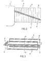
- Figure 2 illustrates how the floating suction pumps can adopt an inclined position with respect to the side of the tanker
- the embodiment of the invention illustrated consists in arranging at the sides of a tanker 1, cages 2, preferably prismatic in shape, which are fixed to the tanker through pivot points 3 so that, by means of fittings 4, such cages 2 can adopt the most suitable position with respect to the longitudinal axis of the tanker.
- each one of these cages 2 is housed a series of suction pumps 5, of prismatic shape, correlatively joined by flexible couplings A.
- the suction pumps 5 are joined by means of said flexible couplings so that they may independently adopt the buyoyancy corresponding thereto, depending on the surface of the sea, i.e. the assembly or battery of suction pumps 5 will adopt the form of the superficial profile of the water.
- the end suction pumps i.e. those situated at one side and the other of the battery which is formed by the correlative joining of the complete assembly, are likewise jointed to the cages 3 by means of flexible couplings. These couplings will be secured to the cages 2 in such a way that they will permit the vertical displacement of the suction pumps along said cages.
- Each suction pump 5 is connected to suction hoses 6 leading to the tanks of the tanker 1, and the front part thereof has a longitudinal opening 9 and a float cut-off valve 7 which controls the inlet of water through said opening 9 .
- the height of the opening is such that, in use, a' lower edge thereof will be positioned below the floating line of the suction pumps at an approximate depth of 0.01 meters.
- the opening 9 communicates with a funnel-shaped - inner cavity of the pump, the smaller dimensioned zone of the cavity communicating with the outside through the hose 6 which protrudes from the bottom of the pump.
- Each suction pump 5 is joined to horizontal guides 8 which prevent said suction pumps from turning on the longitudinal axis thereof, i.e. said guides 8 constitute a type of stabilizer so that the opening 9 is always in the vertical plane, which is the correct position for inlet of water.
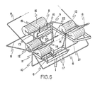
- each suction pump 5 is incorporated in a structure formed by means of the functional combination of two frames formed, for example, from cylindrical tube.
- One of said frames 10 will be referred to as the main or front frame and, as illustrated in Figure 6, is a generally ' rectangular frame.disposed in a vertical plane.
- the frame 10 is provided, at its upper ends, with tubular frames 11 which, in the assembly, adopt a horizontal position and constitute support elements for cylindrical or spherical floaters 12. These geometrical shapes are shown since they are the best to obtain a greater sensitivity to buoyancy.
- floaters 12 are arranged at respective opposite sides of the vertical plane in which said rectangular frame 10 lies.
- a rear frame which will be referred to as the secondary frame, is comprised of a first generally U-shaped tubular portion 13 which, at the free ends of its parallel legs, is pivotally joined at points 14 to the frames 11 which support the floaters 12.
- This first portion 13 of the secondary frame is disposed within the structure, horizontally to receive, at its intermediate transverse leg, another floater 15, while a second tubular portion . 16 of this secondary frame forms a type of bridge which, securely joined to the parallel legs of the first line 13, constitutes a self-supporting structure for the floating suction pump 5.
- both the rectangular frame 10, which forms the main or front frame, and the secondary frame have lower adjustable balancing flaps 17 and 18 in order to prevent, during travel of the tanker, such frames from submerging more than necessary due to the increase in the pressure of the water, i.e. said flaps proportion a constant buoyancy to the assembly.
- suction pump 5 is mounted on the bridge like portion 16, so that the height of the pump can be adjusted.
- the means used to adjust the height may be constituted by studs in which nuts 19 are threaded. This is a very important detail, since said means facilitates the arrangement of the opening 9 of the suction pump 5 and, in this case, an inclined flange 20 thereof at the exact distance with respect to the level of the liquid mass from which the petroliferous products should be collected.
- Said flange 20 whose forward extension can be more or less prolonged, will optionally incorporate an electric resistance of an electric heating circuit so that, with very low temperatures, with the consequent increase in the viscosity of the petroliferous substances, said resistance will provide the products with a raise of temperature so that they may be liquified as much as possible and in this way facilitate the entrances or introduction of the substances into the suction pump.
- the mixture of sea water and petroliferous products absorbed onto the tanker can be separated on the same tanker by means of suitable devices, said products being stored on the tanker while the clean water is returned to the sea* Also, should the relevant installations for a correct separation not be available, the mixture can be unloaded in installations on land then to proceed to the material separation thereof.
- the tanker To collect the contaminated waters from the sea, the tanker should adopt the necessary speed, depending on the absorption capacity provided thereto, since the speed of the tanker should never be greater than the absorption capacity of the suction pumps 5. However, if this occurs, the products would be stored in the front face of the suction pumps which, since they do not have a sufficient absorbing capacity, will pass to the posterior part of the tanker. Therefore, cleaning is rather relative and lacks effectiveness. It is also convenient for the cages 2 to be installed in pairs, i.e. they should preferably be fixed at both sides of the tanker.
- the system for collecting products by means of floating suction pumps presents the advantage that the cost thereof is low, a high operative production is obtained and it is possible, without large financial investments, to install same in any tanker to be used for collecting petroliferous products drifting on the sea.
Landscapes
- Engineering & Computer Science (AREA)
- General Engineering & Computer Science (AREA)
- Environmental & Geological Engineering (AREA)
- Mechanical Engineering (AREA)
- Civil Engineering (AREA)
- Structural Engineering (AREA)
- Cleaning Or Clearing Of The Surface Of Open Water (AREA)
- Structures Of Non-Positive Displacement Pumps (AREA)
- Cleaning In General (AREA)
- Cleaning By Liquid Or Steam (AREA)
- Sampling And Sample Adjustment (AREA)
- Electrical Discharge Machining, Electrochemical Machining, And Combined Machining (AREA)
Applications Claiming Priority (4)
| Application Number | Priority Date | Filing Date | Title |
|---|---|---|---|
| ES483346A ES483346A1 (es) | 1979-08-13 | 1979-08-13 | Sistema de aspiradores flotantes controlados |
| ES483346 | 1979-08-13 | ||
| ES493564A ES8200733A2 (es) | 1980-07-21 | 1980-07-21 | Sistema de aspiradores flotantes controlados |
| ES493564 | 1980-07-21 |
Publications (3)
| Publication Number | Publication Date |
|---|---|
| EP0024187A2 true EP0024187A2 (de) | 1981-02-25 |
| EP0024187A3 EP0024187A3 (en) | 1981-04-22 |
| EP0024187B1 EP0024187B1 (de) | 1984-04-11 |
Family
ID=26155988
Family Applications (1)
| Application Number | Title | Priority Date | Filing Date |
|---|---|---|---|
| EP80302765A Expired EP0024187B1 (de) | 1979-08-13 | 1980-08-12 | System zum Einsammeln von Produkten, die auf die Oberfläche einer Wassermenge gestürzt wurden |
Country Status (8)
| Country | Link |
|---|---|
| US (1) | US4332682A (de) |
| EP (1) | EP0024187B1 (de) |
| DE (1) | DE3067442D1 (de) |
| DK (1) | DK148999C (de) |
| FI (1) | FI74093C (de) |
| IE (1) | IE49969B1 (de) |
| NO (1) | NO153407C (de) |
| PT (1) | PT71696B (de) |
Cited By (2)
| Publication number | Priority date | Publication date | Assignee | Title |
|---|---|---|---|---|
| WO1997019229A1 (en) * | 1995-11-22 | 1997-05-29 | Ilias Gyftonikolos | Swift and cheap method of skimming huge oil spills with any tanker's equipment without chemicals |
| CN1042617C (zh) * | 1992-06-09 | 1999-03-24 | 弗兰西斯克·J·乔里吉·卡罗 | 可控的浮动吸收器系统 |
Families Citing this family (2)
| Publication number | Priority date | Publication date | Assignee | Title |
|---|---|---|---|---|
| US5054312A (en) * | 1987-06-08 | 1991-10-08 | Wilson Ii Charles N | Fuel tank air pocket removal device |
| JP4172560B2 (ja) * | 1998-12-28 | 2008-10-29 | 日本サルヴ▲ヱ▼ージ株式会社 | 液体物質回収方法、および液体物質回収装置 |
Family Cites Families (15)
| Publication number | Priority date | Publication date | Assignee | Title |
|---|---|---|---|---|
| US2497177A (en) * | 1946-11-27 | 1950-02-14 | Standard Oil Dev Co | Differential gravity skimmer |
| US2661094A (en) * | 1950-10-03 | 1953-12-01 | Shell Dev | Variable volume separator for liquids |
| US3534859A (en) * | 1969-03-11 | 1970-10-20 | Gulf Research Development Co | Apparatus for removal of oil floating on water or the like |
| GB1296532A (de) * | 1969-11-21 | 1972-11-15 | ||
| US3615017A (en) * | 1969-12-15 | 1971-10-26 | Joe M Valdespino | Oil entrapment and containment watercraft |
| US3612280A (en) * | 1970-01-21 | 1971-10-12 | Ocean Pollution Control Inc | Oil-skimming apparatus |
| US3759390A (en) * | 1970-03-05 | 1973-09-18 | Megator Pumps Compressor | The removal of surface layers from liquids |
| US3576257A (en) * | 1970-03-18 | 1971-04-27 | Lockheed Aircraft Corp | Fluid separation device |
| US3642140A (en) * | 1970-03-23 | 1972-02-15 | James H Parker | Oil recovery and cleanup system |
| US3653510A (en) * | 1970-04-27 | 1972-04-04 | Ocean Pollution Control Inc | Oil skimming method and apparatus |
| US3745115A (en) * | 1970-07-13 | 1973-07-10 | M Olsen | Method and apparatus for removing and reclaiming oil-slick from water |
| US3726406A (en) * | 1971-02-09 | 1973-04-10 | C Damberger | Oil skimming apparatus |
| US3730346A (en) * | 1971-03-01 | 1973-05-01 | Cortland Skinner | Skimming system |
| US3706382A (en) * | 1971-03-12 | 1972-12-19 | David Parks Hoult | Oil removal device |
| US3753496A (en) * | 1971-12-20 | 1973-08-21 | E Boyd | Converging vortex apparatus for separating oil from water |
-
1980
- 1980-08-06 IE IE1639/80A patent/IE49969B1/en not_active IP Right Cessation
- 1980-08-07 US US06/176,244 patent/US4332682A/en not_active Expired - Lifetime
- 1980-08-12 DE DE8080302765T patent/DE3067442D1/de not_active Expired
- 1980-08-12 FI FI802529A patent/FI74093C/fi not_active IP Right Cessation
- 1980-08-12 PT PT71696A patent/PT71696B/pt not_active IP Right Cessation
- 1980-08-12 NO NO802404A patent/NO153407C/no unknown
- 1980-08-12 DK DK348180A patent/DK148999C/da not_active IP Right Cessation
- 1980-08-12 EP EP80302765A patent/EP0024187B1/de not_active Expired
Cited By (2)
| Publication number | Priority date | Publication date | Assignee | Title |
|---|---|---|---|---|
| CN1042617C (zh) * | 1992-06-09 | 1999-03-24 | 弗兰西斯克·J·乔里吉·卡罗 | 可控的浮动吸收器系统 |
| WO1997019229A1 (en) * | 1995-11-22 | 1997-05-29 | Ilias Gyftonikolos | Swift and cheap method of skimming huge oil spills with any tanker's equipment without chemicals |
Also Published As
| Publication number | Publication date |
|---|---|
| EP0024187B1 (de) | 1984-04-11 |
| NO153407C (no) | 1986-03-12 |
| EP0024187A3 (en) | 1981-04-22 |
| FI74093B (fi) | 1987-08-31 |
| NO802404L (no) | 1981-02-16 |
| PT71696B (en) | 1981-06-26 |
| IE801639L (en) | 1981-02-13 |
| DE3067442D1 (en) | 1984-05-17 |
| US4332682A (en) | 1982-06-01 |
| DK148999C (da) | 1986-10-13 |
| PT71696A (en) | 1980-08-30 |
| IE49969B1 (en) | 1986-01-22 |
| FI802529A7 (fi) | 1981-02-14 |
| NO153407B (no) | 1985-12-02 |
| FI74093C (fi) | 1987-12-10 |
| DK348180A (da) | 1981-02-14 |
| DK148999B (da) | 1985-12-16 |
Similar Documents
| Publication | Publication Date | Title |
|---|---|---|
| US5108591A (en) | Oil spill recovery system | |
| US3822789A (en) | Oil skimmer module with free floating weir trough | |
| US3578171A (en) | Apparatus for removing floating pollutants | |
| US3722687A (en) | Floating oil skimming apparatus with oil and water separator | |
| US4146482A (en) | System for collecting oil | |
| US4892666A (en) | Skimming apparatus and method | |
| US2891672A (en) | Ship for receiving, transporting, and separating immiscible liquids of different specific gravities | |
| US4145292A (en) | Surface skimmer | |
| US3757953A (en) | Decanting skimmer | |
| US2497177A (en) | Differential gravity skimmer | |
| US4664792A (en) | Plant for treatment of urban runoff water | |
| EP0024187B1 (de) | System zum Einsammeln von Produkten, die auf die Oberfläche einer Wassermenge gestürzt wurden | |
| CA1114750A (en) | Floating skimming barrier assemblies | |
| US3727765A (en) | Skimming device for use on a liquid surface | |
| US3849308A (en) | Apparatus for skimming floating pollution from a liquid surface | |
| US4492630A (en) | Bilge system | |
| NO810226L (no) | Lenseelement. | |
| US4197162A (en) | Solar heating using the tide | |
| KR102491863B1 (ko) | 녹조 발생 제어가 가능한 능동형 수상 태양광 발전 시스템 | |
| US5387055A (en) | Oil recovery apparatus and method | |
| SU1387937A1 (ru) | Устройство дл разведени моллюсков | |
| US3706382A (en) | Oil removal device | |
| JPS5925632B2 (ja) | 水域表面に投棄された物質を回収する装置 | |
| SE416635B (sv) | Transportabel kassunanleggning | |
| WO1994028254A1 (en) | Oil skimmer |
Legal Events
| Date | Code | Title | Description |
|---|---|---|---|
| PUAI | Public reference made under article 153(3) epc to a published international application that has entered the european phase |
Free format text: ORIGINAL CODE: 0009012 |
|
| PUAL | Search report despatched |
Free format text: ORIGINAL CODE: 0009013 |
|
| AK | Designated contracting states |
Designated state(s): BE DE FR GB IT NL SE |
|
| AK | Designated contracting states |
Designated state(s): BE DE FR GB IT NL SE |
|
| 17P | Request for examination filed |
Effective date: 19811021 |
|
| ITF | It: translation for a ep patent filed | ||
| GRAA | (expected) grant |
Free format text: ORIGINAL CODE: 0009210 |
|
| AK | Designated contracting states |
Designated state(s): BE DE FR GB IT NL SE |
|
| REF | Corresponds to: |
Ref document number: 3067442 Country of ref document: DE Date of ref document: 19840517 |
|
| ET | Fr: translation filed | ||
| PLBE | No opposition filed within time limit |
Free format text: ORIGINAL CODE: 0009261 |
|
| STAA | Information on the status of an ep patent application or granted ep patent |
Free format text: STATUS: NO OPPOSITION FILED WITHIN TIME LIMIT |
|
| 26N | No opposition filed | ||
| ITTA | It: last paid annual fee | ||
| PGFP | Annual fee paid to national office [announced via postgrant information from national office to epo] |
Ref country code: GB Payment date: 19920828 Year of fee payment: 13 Ref country code: FR Payment date: 19920828 Year of fee payment: 13 |
|
| PGFP | Annual fee paid to national office [announced via postgrant information from national office to epo] |
Ref country code: NL Payment date: 19920831 Year of fee payment: 13 |
|
| PGFP | Annual fee paid to national office [announced via postgrant information from national office to epo] |
Ref country code: SE Payment date: 19920914 Year of fee payment: 13 |
|
| PGFP | Annual fee paid to national office [announced via postgrant information from national office to epo] |
Ref country code: DE Payment date: 19920923 Year of fee payment: 13 |
|
| PGFP | Annual fee paid to national office [announced via postgrant information from national office to epo] |
Ref country code: BE Payment date: 19920930 Year of fee payment: 13 |
|
| PG25 | Lapsed in a contracting state [announced via postgrant information from national office to epo] |
Ref country code: GB Effective date: 19930812 |
|
| PG25 | Lapsed in a contracting state [announced via postgrant information from national office to epo] |
Ref country code: SE Effective date: 19930813 |
|
| PG25 | Lapsed in a contracting state [announced via postgrant information from national office to epo] |
Ref country code: BE Effective date: 19930831 |
|
| BERE | Be: lapsed |
Owner name: CARRO FRANCISCO-JAVIER JAUREGUI Effective date: 19930831 |
|
| PG25 | Lapsed in a contracting state [announced via postgrant information from national office to epo] |
Ref country code: NL Effective date: 19940301 |
|
| GBPC | Gb: european patent ceased through non-payment of renewal fee |
Effective date: 19930812 |
|
| NLV4 | Nl: lapsed or anulled due to non-payment of the annual fee | ||
| PG25 | Lapsed in a contracting state [announced via postgrant information from national office to epo] |
Ref country code: FR Effective date: 19940429 |
|
| PG25 | Lapsed in a contracting state [announced via postgrant information from national office to epo] |
Ref country code: DE Effective date: 19940503 |
|
| REG | Reference to a national code |
Ref country code: FR Ref legal event code: ST |
|
| EUG | Se: european patent has lapsed |
Ref document number: 80302765.5 Effective date: 19940310 |