EP0024251A2 - Scie avec un outil rotatif en forme de tige - Google Patents
Scie avec un outil rotatif en forme de tige Download PDFInfo
- Publication number
- EP0024251A2 EP0024251A2 EP80710018A EP80710018A EP0024251A2 EP 0024251 A2 EP0024251 A2 EP 0024251A2 EP 80710018 A EP80710018 A EP 80710018A EP 80710018 A EP80710018 A EP 80710018A EP 0024251 A2 EP0024251 A2 EP 0024251A2
- Authority
- EP
- European Patent Office
- Prior art keywords
- tool
- cutting
- workpiece
- helix
- pitch
- Prior art date
- Legal status (The legal status is an assumption and is not a legal conclusion. Google has not performed a legal analysis and makes no representation as to the accuracy of the status listed.)
- Granted
Links
Images







Classifications
-
- B—PERFORMING OPERATIONS; TRANSPORTING
- B23—MACHINE TOOLS; METAL-WORKING NOT OTHERWISE PROVIDED FOR
- B23C—MILLING
- B23C3/00—Milling particular work; Special milling operations; Machines therefor
- B23C3/12—Trimming or finishing edges, e.g. deburring welded corners
-
- B—PERFORMING OPERATIONS; TRANSPORTING
- B23—MACHINE TOOLS; METAL-WORKING NOT OTHERWISE PROVIDED FOR
- B23C—MILLING
- B23C5/00—Milling-cutters
- B23C5/02—Milling-cutters characterised by the shape of the cutter
- B23C5/10—Shank-type cutters, i.e. with an integral shaft
Definitions
- the invention relates to a device for machining, in particular for cutting, grooving or smoothing workpieces made of wood, plastic, brass, aluminum or similar, easily machinable - materials with a cutting tool designed as a rotating helix, which with a workpiece support fixedly arranged relative to the tool one end of the coil works together.
- Circular, band, jigsaws, fretsaws and the like are used for cutting workpieces, all of which work according to the principle of the saw, ie cutting the workpiece in the area of a narrow slot is effected with successive sharpened teeth.
- narrow band jig, and Laubsä g s can be used to perform curved cuts in workpieces. With small radii of curvature it is with reciprocating saws or band saws. difficult to make cuts with constant curvature. In the case of leaf and band saws, the size of the workpiece to be processed is limited by the fretsaw bracket or the return of the saw band.
- only circular saws can be used to cut straight grooves. With regard to the efahr for users there are circular saws in the first place and this risk is particularly great when machining small workpieces.
- the invention has for its object to provide a cutting tool and a device intended for machining parts, for example in model construction, in toy manufacture and to a certain extent in furniture construction from materials such as wood, plastic, low strength metal, plasterboard and the like , which acts on the workpiece similar to saws with cutting or cutting forces that run parallel or almost parallel to the tool axis, so that a free, optionally straight or curved, hand-guided cut is made possible, but without the disadvantage of the continuous or the reciprocating movement of saws and without the disadvantage of the forces of known milling cutters acting on the workpiece in the circumferential direction of the tool.
- the workpieces to be machined should all be machined with one and the same tool can.
- the helix angle of this screw is preferably between 5 and 15 °.
- the small pitch angle means that the cutting action is almost parallel to the tool axis in the direction of the fixed support and there is the strong lateral drift, as it is effective with tools whose direction of force when milling is mainly in the circumferential direction, and which increases accordingly with increasing material strength , largely avoided.
- the force to be used for this should be kept low. Apart from the respective material strength, this is determined by the cross section of the surface to be machined, which is derived from the thickness of the workpiece and the diameter of the tool results.
- the tool diameter is therefore kept as small as possible, preferably a maximum of 6 mm, in particular in the case of cutting work, in order to reduce the material waste to a minimum in addition to the lowest possible feed force.
- Carbide is preferred as the material for the tool. It has been found that the best results are achieved with hard metal tools and diameters between 2.5 and 6 mm and a helix pitch of less than 2 mm, namely 1.8 mm with a feed of 0.1 mm per tool revolution. A helix pitch of 1.8 mm ensures that when machining thin workpieces, in particular sheet metal, of only 2 mm thickness, a tool cutting edge is always in engagement with the workpiece and a jerk-free and jerk-free cut is thereby achieved. Specifically, it was found that the following material thicknesses' without the risk of tool breakage can be cut
- woods e.g. spruce, pine, larch, beech, oak
- hardboard e.g. plywood of various qualities and plastics (e.g. hard PVC, Delrin).
- Print templates for model making are particularly suitable for a tool according to the invention with a diameter of approx. 2.5 mm and a pitch of 1.8 mm, whereas a tool with a diameter of 5 mm is suitable for general use and cuts in full up to approx. 25 mm material thickness and approx. 30 mm working length is ideal.
- a tool according to the invention for universal use, in which the risk of breakage is virtually eliminated, so that workpieces up to approx. 40 mm thick can be cut at a reduced feed speed is a conical embodiment, which has a diameter of 6 mm on the shaft and 2 at the upper end mm diameter. If the tool is retracted far into the hollow spindle of the drive unit, thin plates can be separated with minimal waste, since only the thin tool tip is used. With thick workpieces, considerably less material has to be broken up in the upper tool area than in the lower one, which reduces the load on the tool and at the same time the necessary feed force.
- Such a tool is also preferably to be provided with a pitch of less than 2 mm, for example 1.8 mm.
- the spindle of the device can be inclined by the appropriate angle, then an oblique cutting surface is only created on the waste side.
- the cutting force acting on the table has the advantage in the helix according to the invention with a small pitch; that an unwanted lifting of the workpiece is prevented during machining. Furthermore, this property can be used advantageously to achieve geometrically perfect straight cuts. This can be achieved, for example, by arranging a workpiece support provided with a rough covering so that it can be shifted in a straight line on the table and aligning the workpiece in accordance with the desired cutting direction, pressing it down with one hand and feeding it to the tool. When cutting, the workpiece is pressed against the base with almost the entire cutting force and does not deviate to the side, regardless of whether a cutting process is taking place or just smoothing or post-milling.
- the workpiece lintel is preferably a flat table. If necessary, the angle between the screw axis and the main plane of the table can be changed by pivoting the tool or the table.
- the table has a hole through which the free end of the screw protrudes / protrudes.
- the workpiece can be easily cut in any direction lead because the side. Drift is very low, whereas in contrast to cuts with band or jigsaws it is not necessary to twist the workpiece in accordance with the course of the cut, since the worm has the same cutting action on all sides, so that the workpiece is only moved in the X - Y axis got to.
- the workpiece can be of any length and width, it is not hindered by a boom or the like, such as in a jigsaw.
- the high surface quality of the machined surface caused by the scraper-like cut of the helix according to the invention also makes a full cut after a cut, i.e. after a cutting process comparable to sawing, every rework is superfluous, but allows dimensional corrections - in the presence of suitable auxiliary devices - even in the smallest sizes up to a few hundredths of a millimeter.
- accuracies can be achieved that are otherwise only achieved with metal processing equipment or machines, since the helix is much more rigid compared to a band or fretsaw and also with changing cutting conditions such as Hardness differences within a workpiece, with wood also fiber run, feed differences etc. hardly evades.
- a particular advantage of the helix according to the invention with a small pitch is that, unlike milling cutters and saws, it cannot get caught in the workpiece, since the cutting action is not interrupted, but rather is continuous, so that even if the workpiece is brought suddenly or suddenly towards the tool no danger to the Operators can arise. Only when pressure is exerted on the workpiece in the direction of the helix does the cutting process begin, so that an extremely sensitive re-cutting of contours as well as the stopping and restarting of the device in engagement are possible without any danger.
- the excess length can be covered by an attached protective cap, thus largely eliminating the risk of cut injuries if slipping during manual feed.
- the tool according to the invention combines the possibilities that were previously available with different types of saws and milling devices without having the disadvantages of these known tools. If workpiece guidance is required, e.g. for straight or circular cuts, it can be designed very easily.
- the tool according to the invention is used for milling or for cutting figures out of plates according to templates, there can be a cutting-free zone at the free end of the helix or at any other point with which the tool can be guided in or along a template.
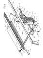
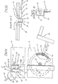
- the tool 1 with the helix of low pitch is fixed (preferably by gluing, soldering, pressing, screwing) / embedded in a shaft 2, the diameter of which is not less than 7 mm and which is longer than that Shaft 4 of drive motor 5 designed as a screed spindle. If necessary, there may be another tool at the other end of shaft 2, which is secured by a protective cap 6 (FIG. 3). At the lower end of the motor shaft 4 there is a clamping screw 7 with which the shaft is clamped and thus secured both axially and against rotation. In order to ensure sufficient clamping without damaging the surface of the shaft, flats 3 are provided in the areas of the shaft in question (FIG. 3).
- the tool 1 protrudes out of the table 8 in an arbitrarily adjustable manner, the relatively large opening 9 in the table 8 being covered by interchangeable insert plates 10 corresponding to the respective tool diameter so that, preferably a gap of only a few tenths of a millimeter between the bore of the insert plate and the tool arises in order to Cutting softer woods and especially plywood to avoid breakouts.
- the motor which is pivotally suspended under the table 8, is preferably used as a two-pole induction motor with e.g. 2800 rpm. should be formed, can be pivoted forwards and backwards by approx. 45 ° and fixed in any position by loosening the knurled nut 11 and tightening it again after the setting, which can be read off from the scale plate 12 in angular degrees.
- a mark 13 attached to the motor housing facilitates the setting or reading.
- the table 8 is fixedly connected to a support 14 shown in FIG. 2, on which the clamping device 15 is located, with which the device e.g. can be attached to a workbench.
- the tool preferably rotates clockwise in relation to the top view and consequently produces a drift of the workpiece which is brought from the front towards the tool to the left, so that the stop, if necessary, is to be attached to the left of the tool. For this reason, the tool is not arranged in the middle of the table, but on the side.
- the format of the table 8 is preferably square in order to be able to use the stop 16 which can be clamped on the table edge both lengthways and crosswise.
- the edge of the table is provided with a bevel 17 in which the correspondingly profiled clamping strips 18 of the stop 16 engage.
- the stop 16 has a recess 20 on one side, the height and width of which are dimensioned such that the tool partially disappears into the inclined position when the stop is placed transversely to the table and pushed correspondingly far over the tool becomes.
- edges can be cut at any angle between 0 and 45 O workpieces 21st
- a continuous groove 21 (FIG. 3, FIG. 4a) in which a removable guide rail 22 slides with a slight play.
- the guide rail is designed as a rack.
- the toothing 23 is in engagement with a pinion 24, which is hidden under the table surface and projects into the groove 22 and is actuated by a feed gear.
- the guide rail 22 is provided with a number of bores with and / or without thread, which serve to accommodate auxiliary devices, and is equipped with a handle 25 so that it can also be used without a feed gear.
- the swinging suspension of the magnet system allows the guide rod in the front of the table to be raised to disengage its teeth from the pinion 24, which is desirable if there is a rapid change the position of the rail is necessary without switching off the feed gear. In this case, the magnet system adheres to the inclined guide rod just as reliably as in the lowered position.
- a similar effect can also be achieved with a V-shaped or semicircular groove in the guide rail and a spring-loaded ball at the end of the groove 21 in the table 8, which engages in the groove of the guide rod 22 , but the magnetic device becomes less wear-resistant and more reliable is preferred.
- an eccentric clamping device is attached to the end of the table.
- the part 31 of the table 8 lying in between is used as a clamping jaw, in that a part located in it. 4b projecting pin 32 below is acted upon by an eccentric 34 and changes its position and also the position of the clamping jaw 31, which enables the guide rail 22 to be clamped in the groove.
- the eccentric 34 is rotatably mounted in the table 8 by means of a bolt 33 and is operated with the handle 35. 35 operated.
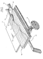
- the feed gear (figures 4a and 5) is operated by an engageable and disengageable crank 36 wherein the gears of the transmission are arranged so that the computing t snavun g of the crank forward movement of the guide rod 22 causes, and the translation is sized to that one turn of the crank corresponds to a feed of approx. 1 mm.
- the shaft 38 mounted in the transmission body 37 and displaceable in the axial direction, one end of which is designed as a bevel pinion 42 is firmly connected to the crank at the other end.
- a compression spring 39 which presses against the shoulder of the crank 36.
- the shaft 38 is provided with a recess 40 into which a resilient wire bracket 41, which is guided in a slot 44 of the gear body, engages and thus axially fixed the shaft without impairing its rotatability.
- the pinion 42 engages in the bevel gear 43, which is firmly connected to the pinion 24, which engages in the payment 23 of the guide rod 22.
- the resilient wire bracket 41 is pressed down by hand and comes out of the puncture of the shaft 38, the compression spring 39 causes the crank 36 to be axially displaced with the shaft 38 and thus the bevel pinion 42 comes out of engagement with the bevel gear 43. In this state, the guide rod can be moved by hand without the relariv. high gear crank is rotated.
- the gear body 37 is designed in such a way that it protects the gearwheels and other functionally important parts of the gearhead from flying chips and damage by the bottom part being cup-shaped and completely covering the gearwheels. Furthermore, it is designed to be removable and is preferably attached to table 8 with a slide and two centering pins.
- auxiliary devices are shown below which, in conjunction with the guide rod 22 or the stop 16, enable a large number of special tasks to be carried out.
- FIG. 7 shows a device which, using the special properties of the tool according to the invention, enables a quick and precise implementation of perfect geometrically straight cuts.
- the device consists of a plate 46, preferably of sheet metal, which by means of two pins 47, which are located on the underside of the plate and engage in corresponding bores in the guide rail 22, can be attached to the latter by simply plugging them on.
- the plate 46 is provided with a longitudinal groove 48 which is arranged such that the tool 1 projects through it and does not touch its lateral boundary surfaces.
- the groove is preferably 0.2 to 0.3 mm wider than the diameter of the tool.
- the length of the plate and the groove are preferably to be possessed such that the length of the work path corresponds to the length of the work path of the guide rail.
- the plate is provided with a rough covering 49.
- This can consist of glued-on emery cloth or paper, of a directly applied corundum grain or the like, or can be created by mechanical treatment of the plate surface in the manner in which files are cut.
- line markings on the right and left edge of the plate which represent an angular division and make it possible to align workpieces for miter cuts according to these without the aid of measuring instruments.
- the columns 50 are removable so as not to be a hindrance when machining workpieces larger than the plate.
- a support attachment 53 can be fastened to the front end of the plate 46 in bores provided for this purpose, which receives a pivotable jaw 54 on the side facing the tool, on which a workpiece in any position Angular position can be supported.
- the underside of the plate according to FIG. 8 or the table can be provided with a friction-reducing coating, e.g. the plate must be coated with Teflon, which also prevents scratching.
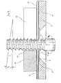
- Fi g . 8 shows in a greatly enlarged section the arrangement of the Tool to the table and its effect on a workpiece that is on the plate with a rough surface.
- a workpiece 58 is shown, into which a slot 59 has already been cut by the tool 1, the removal taking place at the location 60 of the workpiece by the tool.
- This tool protrudes with its free end through a hole 9 in the table 8, which is covered by the insert plate 10 except for a bore 61 adapted to the tool diameter, and can optionally be adjusted in the direction of its axis 62, so that grooves are also milled into workpieces , can be.
- the table 8 or the tool 1 can be pivoted so that cuts that run at an angle to the main planes on flat workpieces can be carried out.
- the plate 46 On the table lies the plate 46, which is connected to the guide rail 22 (not shown here) and can be moved in a straight line with the latter.
- the workpiece 58 adheres to the rough covering 49 located on the plate.
- the underside of the plate 46 is provided with a sliding covering 57, such as a Teflon coating.
- auxiliary device is shown ind Fig. 9.
- a prism 55 which can be plugged onto the guide rail 22 is used, the distance to the tool 1 from which can be changed by displacing the guide rail 22.
- the desired setting can be fixed by clamping the guide rail. Now it is sufficient to press the circular workpiece against the prism and turn it by hand in a direction opposite to the tool rotation in order to cut out the opening to the desired size concentrically with the outside diameter.
- FIG. 10 shows an arrangement in which the tool 1 according to the invention protrudes through a bore 61 in a tool table 8. If necessary, the tool can be guided out of the work table to different degrees by an adjusting device (not shown).
- the essence of the invention is that the workpiece can be guided without mechanical or other guide aids in a main direction, which is indicated by the arrow 66, without forces occurring that could endanger the person carrying the workpiece. No fixed guidance is required for the workpiece 63 in a direction perpendicular to the worm, since this worm does not exert any appreciable forces on the workpiece in any direction perpendicular to its own axis.
- a drill tip 69 can be provided at the free end of the unthreaded zone 65, by means of which a bore can be made in a workpiece, so that e.g. a curved slot can be introduced, which does not need to be guided to the edge of the workpiece, by placing the workpiece on the drill tip 69 from above and pressing it on the table 8, whereby a simple hole is first made in the workpiece, which is then by guiding the workpiece along the edge 68 of the template 64 can be extended to an arbitrarily long slot.
- Fig. 1, 1 a device is illustrated with the aid of which it is possible to perform in thick workpieces without the effort which would normally apply for the feed manually swept e g cuts using the Vorschubgetribes.
- a boom 70 is attached, at the end of which a trailing arm 71 is mounted so that it can swing to the right and left.
- the height of the trailing arm can be changed to match the thickness of the workpiece.
- the drag arm 71 has at its free end a driver pin 72 which engages in a bore to be made in the workpiece.
- Fig. 12 shows a device for cutting bevels on round or otherwise curved, plate-shaped workpieces.
- the disc to be machined To cut a bevel, the disc to be machined, the center bore of which must correspond to the diameter of the pin 78, is plugged onto it until it abuts against the flat surface of the round body 77 and is pushed downward along it with the slot 76 until it is on the Table 8 supports.
- the correspondingly dimensioned projection 79 of the guide piece 75 scrubs for the rear support of the workpiece when cutting.
- the stop 16 with the device and the workpiece 79 located thereon which is shown in partial section in FIG. 12, is pushed as far as the rotating tool until the desired one Milling depth is reached.
- the stop is now clamped on the table and the. Disc rotated by hand.
- the cutting force inherent in the tool according to the invention acting almost along its longitudinal axis, causes the workpiece to be pressed both against the table and against the projection 79 acting as a rear support, which enables a clean carving.
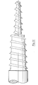
- FIG. 13 shows an enlarged view of a conical design of the tool 1 '.
- the risk of injury is reduced to a minimum, in particular it is incomparably lower than with circular saws, band saws, milling machines and planers, provided that small workpieces are processed.
- the drive is quiet, since no high speeds are necessary.
- the helix cuts almost noiselessly and produces fine crimping shavings that mostly fall under the table without being flung away by tools, such as with circular saws and planers. There is almost no dust.
Landscapes
- Engineering & Computer Science (AREA)
- Mechanical Engineering (AREA)
- Sawing (AREA)
- Milling, Drilling, And Turning Of Wood (AREA)
- Electrical Discharge Machining, Electrochemical Machining, And Combined Machining (AREA)
Priority Applications (1)
| Application Number | Priority Date | Filing Date | Title |
|---|---|---|---|
| AT80710018T ATE4489T1 (de) | 1979-08-17 | 1980-07-23 | Stichsaege mit stabfoermigen rotierenden werkzeug. |
Applications Claiming Priority (2)
| Application Number | Priority Date | Filing Date | Title |
|---|---|---|---|
| DE2933380A DE2933380C2 (de) | 1979-08-17 | 1979-08-17 | Stichsäge |
| DE2933380 | 1979-08-17 |
Publications (3)
| Publication Number | Publication Date |
|---|---|
| EP0024251A2 true EP0024251A2 (fr) | 1981-02-25 |
| EP0024251A3 EP0024251A3 (en) | 1981-07-01 |
| EP0024251B1 EP0024251B1 (fr) | 1983-08-24 |
Family
ID=6078705
Family Applications (1)
| Application Number | Title | Priority Date | Filing Date |
|---|---|---|---|
| EP80710018A Expired EP0024251B1 (fr) | 1979-08-17 | 1980-07-23 | Scie avec un outil rotatif en forme de tige |
Country Status (4)
| Country | Link |
|---|---|
| EP (1) | EP0024251B1 (fr) |
| JP (1) | JPS6015443B2 (fr) |
| AT (1) | ATE4489T1 (fr) |
| DE (1) | DE2933380C2 (fr) |
Cited By (3)
| Publication number | Priority date | Publication date | Assignee | Title |
|---|---|---|---|---|
| FR2561556A1 (fr) * | 1984-03-26 | 1985-09-27 | Recoules Fils Sa | Outil de detourage de materiaux composites |
| US4947908A (en) * | 1990-01-31 | 1990-08-14 | Black & Decker, Inc. | Method and tool for forming biscuit joints |
| CN118493533A (zh) * | 2024-05-20 | 2024-08-16 | 浙江览春木业有限公司 | 一种数控木方四角倒圆机 |
Families Citing this family (5)
| Publication number | Priority date | Publication date | Assignee | Title |
|---|---|---|---|---|
| DE3341329A1 (de) * | 1983-11-15 | 1985-05-23 | Licentia Patent-Verwaltungs-Gmbh, 6000 Frankfurt | Einrichtung fuer einen motorisch angetriebenen handhobel zum fuehren von werkstuecken |
| DE3624076A1 (de) * | 1986-07-17 | 1988-02-04 | Frank Geb Weiss | Horizontal bohrvorrichtung |
| JP2005111761A (ja) * | 2003-10-06 | 2005-04-28 | Kuraray Co Ltd | シート切断装置 |
| CN116748951B (zh) * | 2023-08-16 | 2023-10-27 | 二重(德阳)重型装备有限公司 | 异形锥形孔的数控加工方法 |
| CN119159647B (zh) * | 2024-11-20 | 2025-07-29 | 福建省尤溪县百源木业有限公司 | 一种全自动木材加工机 |
Family Cites Families (12)
| Publication number | Priority date | Publication date | Assignee | Title |
|---|---|---|---|---|
| DE97884C (fr) * | ||||
| DE480721C (de) * | 1928-08-22 | 1929-08-07 | Alfred Melchers | Feile mit Fuehrungsdorn |
| GB350083A (en) * | 1930-03-21 | 1931-06-11 | James William Holmes | An improved spiral rotary cutterhead and knives for wood smoothing and planing and like machines |
| CH161618A (de) * | 1932-07-04 | 1933-05-15 | Hertli Alfred | Messerwelle für Hobelmaschinen. |
| DE635172C (de) * | 1933-06-23 | 1936-09-11 | Fritz Werner Akt Ges | Fraeser mit unter kleinem Steigungswinkel verlaufenden Umfangszaehnen |
| US2670018A (en) * | 1949-09-30 | 1954-02-23 | Alta Engineering Company | Rotary cutting tool |
| GB680412A (en) * | 1951-03-22 | 1952-10-01 | Michael Pinto | Milling cutters |
| CH310708A (de) * | 1953-12-22 | 1955-10-31 | Degen Hugo | Bohrer zum Bohren von Dübellöchern. |
| US3003224A (en) * | 1958-02-06 | 1961-10-10 | Weldon Tool Co | Cutting tool |
| US3704517A (en) * | 1970-12-07 | 1972-12-05 | Thomas M Deterling | Rotating rod saw and method of making same |
| US3863316A (en) * | 1973-12-07 | 1975-02-04 | Herbert G Yeo | Rotary cutting tool and method of manufacturing same |
| DE2553387A1 (de) * | 1975-11-27 | 1976-12-09 | Fama Maschinenbau Ag | Automatische lichtausschnittmaschine zur herstellung von ausschnitten fuer einzusetzende scheiben bei plattenfoermigen koerpern wie tueren u.dgl. |
-
1979
- 1979-08-17 DE DE2933380A patent/DE2933380C2/de not_active Expired
-
1980
- 1980-07-23 AT AT80710018T patent/ATE4489T1/de not_active IP Right Cessation
- 1980-07-23 EP EP80710018A patent/EP0024251B1/fr not_active Expired
- 1980-08-18 JP JP55113313A patent/JPS6015443B2/ja not_active Expired
Cited By (3)
| Publication number | Priority date | Publication date | Assignee | Title |
|---|---|---|---|---|
| FR2561556A1 (fr) * | 1984-03-26 | 1985-09-27 | Recoules Fils Sa | Outil de detourage de materiaux composites |
| US4947908A (en) * | 1990-01-31 | 1990-08-14 | Black & Decker, Inc. | Method and tool for forming biscuit joints |
| CN118493533A (zh) * | 2024-05-20 | 2024-08-16 | 浙江览春木业有限公司 | 一种数控木方四角倒圆机 |
Also Published As
| Publication number | Publication date |
|---|---|
| EP0024251A3 (en) | 1981-07-01 |
| JPS6015443B2 (ja) | 1985-04-19 |
| DE2933380C2 (de) | 1983-07-28 |
| ATE4489T1 (de) | 1983-09-15 |
| EP0024251B1 (fr) | 1983-08-24 |
| DE2933380A1 (de) | 1981-02-26 |
| JPS5644608A (en) | 1981-04-23 |
Similar Documents
| Publication | Publication Date | Title |
|---|---|---|
| DE10251578B3 (de) | Führungsschiene für Handwerkzeugmaschinen mit zugeordnetem Anschlagstück | |
| EP0024251B1 (fr) | Scie avec un outil rotatif en forme de tige | |
| DE3615848C2 (fr) | ||
| EP0382877B1 (fr) | Dispositif pour dégauchir et réduire l'épaisseur de pièces de bois d'une taille quelconque, en particulier des pièces minces et courtes | |
| DE4216338C2 (de) | Schutzhaube für Holzfräsmaschinen | |
| EP0211838B1 (fr) | Installation de sciage et de coupe pour troncs d'arbre | |
| EP0335084A2 (fr) | Dispositif et outil de production de tous les types de filets (sauf filet de scie) en une seule opération | |
| DE3004881A1 (de) | Vorrichtung zum abschraegen von kanten an werkstuecken, insbesondere blechen | |
| DE2636529A1 (de) | Saegemaschine fuer oberflaechenbeschichtete platten | |
| DE102005020485B3 (de) | Bündigfräs- und Abziehaggregat | |
| DE202020003677U1 (de) | Fräsvorrichtung | |
| DE3422101C2 (fr) | ||
| DE4337681C1 (de) | Verfahren und Vorrichtung zum Aussägen von im wesentlichen kreisförmigen Scheiben aus im wesentlichen plattenförmigem Material | |
| WO2010054631A1 (fr) | Scie à encoches | |
| DE623090C (de) | Vorschubvorrichtung fuer Holzbearbeitungsmaschinen | |
| DE7923533U1 (de) | Drehstabsaege | |
| DE202007017278U1 (de) | Tragbare Maschine zur Eckenbearbeitung | |
| DE102008057031A1 (de) | Geführte Ausschnittsäge | |
| DE3318747C2 (de) | Führungseinrichtung für Handhobel- oder Fräsgeräte | |
| DE19856278A1 (de) | Hobelmesser für Hobelmaschinen, insbesondere Handhobelmaschinen für die Holzbearbeitung | |
| DE19713445A1 (de) | Umleimer-Fräsmaschine | |
| DE19527098C1 (de) | Zinkenschneideinrichtung | |
| EP2353817A2 (fr) | Système de chevilles en bois | |
| DE102010039108A1 (de) | Handwerkzeugmaschine, insbesondere Säge, wie Kreissäge, Stichsäge od. dgl. | |
| DE4224052C2 (de) | Anschlagwinkel für Handarbeitsmaschine |
Legal Events
| Date | Code | Title | Description |
|---|---|---|---|
| PUAI | Public reference made under article 153(3) epc to a published international application that has entered the european phase |
Free format text: ORIGINAL CODE: 0009012 |
|
| AK | Designated contracting states |
Designated state(s): AT CH FR GB IT SE |
|
| PUAL | Search report despatched |
Free format text: ORIGINAL CODE: 0009013 |
|
| AK | Designated contracting states |
Designated state(s): AT CH FR GB IT SE |
|
| 17P | Request for examination filed |
Effective date: 19810615 |
|
| ITF | It: translation for a ep patent filed | ||
| GRAA | (expected) grant |
Free format text: ORIGINAL CODE: 0009210 |
|
| AK | Designated contracting states |
Designated state(s): AT CH FR GB IT LI SE |
|
| REF | Corresponds to: |
Ref document number: 4489 Country of ref document: AT Date of ref document: 19830915 Kind code of ref document: T |
|
| ET | Fr: translation filed | ||
| PLBE | No opposition filed within time limit |
Free format text: ORIGINAL CODE: 0009261 |
|
| STAA | Information on the status of an ep patent application or granted ep patent |
Free format text: STATUS: NO OPPOSITION FILED WITHIN TIME LIMIT |
|
| PGFP | Annual fee paid to national office [announced via postgrant information from national office to epo] |
Ref country code: FR Payment date: 19840720 Year of fee payment: 5 |
|
| PGFP | Annual fee paid to national office [announced via postgrant information from national office to epo] |
Ref country code: CH Payment date: 19840824 Year of fee payment: 5 |
|
| 26N | No opposition filed | ||
| PGFP | Annual fee paid to national office [announced via postgrant information from national office to epo] |
Ref country code: SE Payment date: 19840930 Year of fee payment: 5 |
|
| PGFP | Annual fee paid to national office [announced via postgrant information from national office to epo] |
Ref country code: AT Payment date: 19860715 Year of fee payment: 7 |
|
| PG25 | Lapsed in a contracting state [announced via postgrant information from national office to epo] |
Ref country code: GB Effective date: 19880723 Ref country code: AT Effective date: 19880723 |
|
| PG25 | Lapsed in a contracting state [announced via postgrant information from national office to epo] |
Ref country code: SE Effective date: 19880724 |
|
| PG25 | Lapsed in a contracting state [announced via postgrant information from national office to epo] |
Ref country code: LI Effective date: 19880731 Ref country code: CH Effective date: 19880731 |
|
| GBPC | Gb: european patent ceased through non-payment of renewal fee | ||
| PG25 | Lapsed in a contracting state [announced via postgrant information from national office to epo] |
Ref country code: FR Free format text: LAPSE BECAUSE OF NON-PAYMENT OF DUE FEES Effective date: 19890331 |
|
| REG | Reference to a national code |
Ref country code: CH Ref legal event code: PL |
|
| REG | Reference to a national code |
Ref country code: FR Ref legal event code: ST |
|
| EUG | Se: european patent has lapsed |
Ref document number: 80710018.5 Effective date: 19890510 |