EP0024732A2 - Cellule à mémoire monolithique statique, procédé pour sa fabrication et procédé pour son opération - Google Patents
Cellule à mémoire monolithique statique, procédé pour sa fabrication et procédé pour son opération Download PDFInfo
- Publication number
- EP0024732A2 EP0024732A2 EP80105133A EP80105133A EP0024732A2 EP 0024732 A2 EP0024732 A2 EP 0024732A2 EP 80105133 A EP80105133 A EP 80105133A EP 80105133 A EP80105133 A EP 80105133A EP 0024732 A2 EP0024732 A2 EP 0024732A2
- Authority
- EP
- European Patent Office
- Prior art keywords
- layer
- interface
- region
- memory cell
- recess
- Prior art date
- Legal status (The legal status is an assumption and is not a legal conclusion. Google has not performed a legal analysis and makes no representation as to the accuracy of the status listed.)
- Ceased
Links
- 230000015654 memory Effects 0.000 title claims abstract description 63
- 238000000034 method Methods 0.000 title claims abstract description 28
- 230000003068 static effect Effects 0.000 title claims abstract description 11
- 238000004519 manufacturing process Methods 0.000 title claims abstract description 6
- 230000008569 process Effects 0.000 title abstract description 6
- 239000004065 semiconductor Substances 0.000 claims abstract description 71
- 229910021420 polycrystalline silicon Inorganic materials 0.000 claims abstract description 21
- 238000001020 plasma etching Methods 0.000 claims abstract description 20
- 229920005591 polysilicon Polymers 0.000 claims abstract description 10
- 238000002347 injection Methods 0.000 claims abstract description 9
- 239000007924 injection Substances 0.000 claims abstract description 9
- 239000002800 charge carrier Substances 0.000 claims description 13
- 238000009413 insulation Methods 0.000 claims description 9
- 238000005530 etching Methods 0.000 claims description 8
- 238000002513 implantation Methods 0.000 claims description 8
- 238000000576 coating method Methods 0.000 claims description 7
- 230000003647 oxidation Effects 0.000 claims description 7
- 238000007254 oxidation reaction Methods 0.000 claims description 7
- 239000011248 coating agent Substances 0.000 claims description 5
- 239000011159 matrix material Substances 0.000 claims description 3
- 238000005468 ion implantation Methods 0.000 claims 3
- 238000012546 transfer Methods 0.000 abstract description 6
- 238000005516 engineering process Methods 0.000 abstract description 5
- 230000008929 regeneration Effects 0.000 abstract description 4
- 238000011069 regeneration method Methods 0.000 abstract description 4
- 229910004298 SiO 2 Inorganic materials 0.000 description 12
- 150000002500 ions Chemical class 0.000 description 6
- XUIMIQQOPSSXEZ-UHFFFAOYSA-N Silicon Chemical compound [Si] XUIMIQQOPSSXEZ-UHFFFAOYSA-N 0.000 description 5
- 229910052710 silicon Inorganic materials 0.000 description 5
- 239000010703 silicon Substances 0.000 description 5
- 238000010586 diagram Methods 0.000 description 4
- 239000007787 solid Substances 0.000 description 4
- 230000005669 field effect Effects 0.000 description 3
- 238000001465 metallisation Methods 0.000 description 3
- 230000009471 action Effects 0.000 description 2
- 229910052785 arsenic Inorganic materials 0.000 description 2
- 238000000151 deposition Methods 0.000 description 2
- 230000008021 deposition Effects 0.000 description 2
- 238000011161 development Methods 0.000 description 2
- 230000018109 developmental process Effects 0.000 description 2
- 238000009792 diffusion process Methods 0.000 description 2
- 230000005684 electric field Effects 0.000 description 2
- 239000000463 material Substances 0.000 description 2
- RQNWIZPPADIBDY-UHFFFAOYSA-N arsenic atom Chemical compound [As] RQNWIZPPADIBDY-UHFFFAOYSA-N 0.000 description 1
- -1 arsenic ions Chemical class 0.000 description 1
- 230000004888 barrier function Effects 0.000 description 1
- 239000003795 chemical substances by application Substances 0.000 description 1
- 150000001875 compounds Chemical class 0.000 description 1
- 238000013461 design Methods 0.000 description 1
- 238000011156 evaluation Methods 0.000 description 1
- 239000012774 insulation material Substances 0.000 description 1
- 230000000873 masking effect Effects 0.000 description 1
- 229910052751 metal Inorganic materials 0.000 description 1
- 239000002184 metal Substances 0.000 description 1
- HZVOZRGWRWCICA-UHFFFAOYSA-N methanediyl Chemical compound [CH2] HZVOZRGWRWCICA-UHFFFAOYSA-N 0.000 description 1
- 230000008520 organization Effects 0.000 description 1
- 230000000149 penetrating effect Effects 0.000 description 1
- 230000000737 periodic effect Effects 0.000 description 1
- 229920002120 photoresistant polymer Polymers 0.000 description 1
- 238000012545 processing Methods 0.000 description 1
- 230000000717 retained effect Effects 0.000 description 1
- 239000000126 substance Substances 0.000 description 1
- 230000007704 transition Effects 0.000 description 1
Images


Classifications
-
- G—PHYSICS
- G11—INFORMATION STORAGE
- G11C—STATIC STORES
- G11C11/00—Digital stores characterised by the use of particular electric or magnetic storage elements; Storage elements therefor
- G11C11/21—Digital stores characterised by the use of particular electric or magnetic storage elements; Storage elements therefor using electric elements
- G11C11/34—Digital stores characterised by the use of particular electric or magnetic storage elements; Storage elements therefor using electric elements using semiconductor devices
- G11C11/35—Digital stores characterised by the use of particular electric or magnetic storage elements; Storage elements therefor using electric elements using semiconductor devices with charge storage in a depletion layer, e.g. charge coupled devices
-
- H—ELECTRICITY
- H10—SEMICONDUCTOR DEVICES; ELECTRIC SOLID-STATE DEVICES NOT OTHERWISE PROVIDED FOR
- H10B—ELECTRONIC MEMORY DEVICES
- H10B10/00—Static random access memory [SRAM] devices
- H10B10/15—Static random access memory [SRAM] devices comprising a resistor load element
Definitions
- the invention relates to a monolithic static memory cell according to the preamble of claim 1, and to methods for its manufacture and for its operation.
- Static RAM memory cells consist of a plurality of field-effect transistors built up in MIS technology (metal insulating layer semiconductor technology) and integrated on a semiconductor body.
- MIS technology metal insulating layer semiconductor technology
- a part of an interface of the semiconductor body corresponding to the number of field effect transistors must be made available.
- dynamic, single-transistor memory cells integrated on a semiconductor body are known (cf. IEEE Journal cf Solid State Circuits, Vol. SC-7, No.5, October 1972, pages 336-340), which have a much smaller part of its interface claim, but must be operated so that the stored in them periodically read, regenerated and read again. A regeneration of the stored information is also necessary when reading out.
- the invention has for its object to provide a static memory cell that can be realized on a significantly smaller semiconductor area than the conventional static memory cells. This object is achieved by the features characterized in claim 1.
- the static memory cell according to the invention is characterized in particular by the fact that it has a low need for semiconductor area comparable to a dynamic one-transistor memory cell, without the disadvantages of the periodic regeneration of the stored digital information which occur in dynamic memory cells and which have already been mentioned . Therefore, when used in semiconductor memories, the static memory cell according to the invention allows the bit density to be increased to values that can otherwise only be achieved with dynamically operated memory cells, without the additional circuitry required for the latter having to be borne for regeneration and clocking.
- a doped Semiconductor body 1 for example made of n-type silicon, which is covered with a semiconductor layer 2 of opposite conductivity, for example made of p-type silicon. At the interface 2a of this layer there is an area 3 doped opposite thereto, which is n-conducting in the example mentioned.
- a first drive line (bit line), which is shown as a conductive assignment 4 with a connection 5, makes contact with the region 3.
- a gate 6 is arranged, which is separated from the interface 2a by a gate insulation 7 and by lateral parts the layer representing the gate insulation, which consists, for example, of SiO 2 , is also electrically insulated in the lateral direction from the adjacent circuit parts.
- the gate 6 is part of a second drive line (word line) which has an end connection 8, or is connected to a word line via this connection 8.
- word line a second drive line
- an electrically conductive covering 9 is provided, which is separated from the surface 2a by a very thin electrically insulating layer 10, for example made of SiO 2 .
- the thickness of the layer 10 is chosen so that it allows a tunnel current between the interface 2a and the conductive covering 9.
- the latter is connected via a load element, which is indicated in FIG. 1 by a resistance symbol, to a connection 12 which is connected to a voltage V D.
- the semiconductor body 1 is provided with a connection 13, to which a voltage V Sub is supplied.
- the memory cell is surrounded by a trench-shaped recess 14 which extends from the interface 2a into the semiconductor body 1 and is filled with an electrically insulating layer, in particular an oxide layer 15.
- the circuit parts 14, 15 can also be arranged in a manner that extends in a vertical direction from the interface 2a to the interface 1a and in In the lateral direction, the semiconductor zone corresponding to the dimensions of the recess 14, the conductivity type of which corresponds to that of the semiconductor body 1, may be replaced.
- the voltage V D constantly supplied to the connection 12 causes a space charge zone 16 to form below the conductive assignment 9.
- the negative charge carriers thermally generated in this zone 16 reach the interface 2a under the influence of the electric field prevailing in the zone, while the positive charge carriers 18 the terminal 13 are supplied.
- the very thin insulating layer 10 allows the negative charge carriers 17 to pass through, which then continue to be fed to the connection 12, so that a generation current flowing back to the charge carriers 17 and 18 flows between the connections 12 and 13.
- the operating state shown in FIG. 3 differs from that according to FIG. 2 in that an inversion layer or inversion charge 19 is located at the interface 2a below the conductive covering 9, under the influence of which the space charge zone 16 is reduced.
- the circuit parts 19, 2 and 1 represent a bipolar transistor, the emitter zone of which is formed by the semiconductor body 1 and the base zone of which is formed by the semiconductor layer 2.
- the collector of this transistor is represented by the inversion layer 19.
- an injection current indicated by the arrow 20 arises from negative charge carriers, which are injected from the semiconductor body 1 via the interface 1 a into the layer 2 and reach the inversion collector 19.
- a significantly larger tunnel current is created through the insulating layer 10 than in that Operating state according to FIG. 2, the negative charge carriers reaching terminal 12 again. There is thus an injection current between the connections 12 and 13, the size of which is determined by the tunnel current.
- FIG. 4 shows a potential profile ⁇ along the line A-A in FIG. 2, FIG. 5 in the upper part a cross section containing this line through the arrangement according to FIG. 2, which runs perpendicular to the image plane of FIG.
- the circuit parts 1, 2 and 9 to 13 of Figure 5 have already been described with reference to Figures 1 and 2.
- the potential profile 0 plotted over the distance z from the upper end of the load element 11 in FIG. 4 shows that the small generation current at the load element 11 causes a very small potential drop, while the potential drop occurring at the insulating layer 10 is designated by 20.
- the potential ⁇ drops to the potential ⁇ 1 of the semiconductor layer 2, while in the space charge zone 21, which builds up together with the space charge zone 22 at the interface 1a, there is a potential increase 23 to approximately the value 24, which corresponds to the Potential of the semiconductor body 1 corresponds.
- FIG. 6 shows the potential profile 0 along the line BB in FIG. 3 in a diagram corresponding to FIG. 4, a smaller space charge zone 16 'now having to be taken into account, which is indicated in FIG. 5.
- the much larger injection current results in a voltage drop 25 in the load element 11, an increased voltage drop 20 1 on the insulating layer 10, a reduced voltage drop within 16 'to the value ⁇ 1' of the layer 2 which is now increased by the forward voltage FS, and a reduced potential increase 23 ' approximately to the value 24, which again corresponds to the potential of the semiconductor body 1.
- 7 shows the current-voltage characteristic of a bistable element consisting of parts 2, 16, 10 and 9. In this diagram, the current I flowing through the element is plotted against the voltage V applied to parts 2 and 9.
- the characteristic curve has two branches 25 and 26 which, together with a resistance line 27 corresponding to the load element 11, result in two intersection points 28 and 29. Each of these intersections represents a stable working point of the tunnel element.
- the elements 10, 9, 16 and 2 together with 11 and the semiconductor body 1 form a subcircuit which is operated in two stable switching states defined by the operating points 28 and 29, the selection between the operating points 28 and 29 being determined by the size of the the connections 12 and 13 flowing current.
- a small generation current flows, which causes the voltage 20 or the operating point 28 to be adjusted via the characteristic curve according to FIG.
- the operating point 29 is set by the large injection current present, which causes a voltage 20 1 to drop across the insulating layer 10.
- the injection current prevents the inversion charge 19 from being reduced, while in the first case the small tunnel current corresponding to the generation current prevents the build-up of an undesired inversion charge at the interface 2a below the conductive assignment 9.
- the memory element is now operated in such a way that the bit line 4 is connected to a high potential V 0 via the connection 5 in order to write in first digital information, which is given, for example, by a logic “0” becomes.
- the word line 6 is connected via its connection 8 to a gate voltage V G which inverts the semiconductor layer below 6 and results in the establishment of a transfer channel at the interface 2a.
- the voltage V D at the terminal 12 generates a surface potential at the interface 2a below the assignment 9, which is smaller than the potential of the area 3 connected to the bit line 4. Therefore, no charge carriers from the area 3 reach the interface 2a below 10 transported and no inversion charge forms there. This results in the operating state explained with reference to FIG. 2, in which a small generation current flows and the operating point 28 is set.
- V G is switched off and the bit line 4 is thus separated from the memory element.
- the bit line 4 is connected to a low voltage V 1 via the connection 5.
- the gate voltage V G generating a transfer channel is again fed to the terminal 8.
- Charge carriers from region 3 are injected into the semiconductor layer 2 and accumulate under the occupancy 9 connected with V D in the form of an inversion charge.
- the operating state according to FIG. 3 results, in which a large injection current flows, which corresponds to the working point 29. This injection current maintains the inversion charge after switching off V G or disconnecting bit line 4 from the memory element.
- the bit line 4 is first reset to a reference potential and then released from external potentials, so that it is in a "floating" state.
- the gate voltage V G is then again applied to the gate 6.
- Different potential changes that arise on the bit line 4 depending on the presence or absence of an inversion charge 19 are evaluated as read signals for different stored digital information by being fed to the gate of an input-side field effect transistor of an evaluation stage and influencing the current flowing through it a load element arising voltage drop can be based on another logical 'processing.
- the bit line 4 is expediently reset to a high reference potential for reading out, so that when reading a logical "1" through the charge carriers penetrating into 3 there is a significant voltage drop on the bit line 4, while when reading out a logical "0" due to the lack of an inversion charge 19 that Reset potential on bit line 4 is retained.
- the gate 6 is formed as part of a conductive assignment of a first assignment level, which represents the word line.
- the bit line 4 consists of a conductive assignment in the form of a meandering strip which contacts the area 3 and runs outside the contact area in a second assignment level. Part of another meandering bele supply 30 illustrates the assignment 9 (Fig.1).
- the assignments 6, 4 are preferably made of harnessdot i Ertem, polycrystalline silicon and by insulating intermediate layers 32, preferably made of Si0 2, separated from each other.
- the coating 30 is guided up to this layer 10.
- the covering 30 can be lightly doped in the region of the recess 31, while it is undoped in its remaining parts. The stronger this doping, the smaller the resistance of the load element.
- the connection from the load element 11 to the connection 12 takes place in FIG. 8 via a strip-like metallization 30a which runs parallel or perpendicular to the image plane.
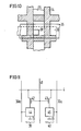
- FIG. 8 shows a symmetrical development of the arrangement according to FIG. 1, in which two transfer elements 3-8 or 3'-8 'are arranged to the left and right of a central plane of symmetry SE, which are connected to a common thin insulating layer 10 and border a common conductive assignment 9.
- Fig. 9 shows the lay-out of an arrangement according to Fig. 8.
- the insulation zones 14, 15 are indicated by hatched strips 34, while the word line 6 is identified by a strip 35, the bit line 4 by a strip 36 and the assignment 30 by a strip 37.
- the recess 31 in FIG. 8 is marked accordingly in FIG. 9.
- a recess 38 is provided which corresponds to the recess 31, but in a corner of the insulation zones 14 provided for a memory cell. 15 enclosed semiconductor surface is.
- FIG. 11 shows an expedient organizational form of a memory matrix constructed from memory cells according to the invention.
- the transfer elements of the memory cells are denoted by 42 and 43, while the bistable circuits 1, 2, 9, 10 and 11 of the memory cells are indicated by blocks 44 and 45.
- the memory cells 39 and 40 lying in a matrix row have a common bit line 4, the memory cells combined in one column have common word lines 6, which in the case of FIG. 11 are represented by a word line 41 lying between two columns and common to all memory cells of these two columns .
- the strip-shaped metallizations 30a run parallel to the word lines 41, while the ground connections of the bistable subcircuits 44, 45 are formed by the connection 13 of the semiconductor body 1.
- the load element 11 has a small resistance or is to be completely dispensed with, the part of the covering 30 formed from polysilicon, which is in the region of the recess 31, is heavily doped. If the doping is weak, this part of the assignment 30 represents an element which corresponds to parts 9 and 11 of FIG. 1.
- the layer 10 can be omitted if the part of the polycrystalline coating 30 which then contacts the interface 2a remains undoped.
- the thin insulating layer 10 can be realized, for example, by an SiO 2 layer with a layer thickness of approximately 30-60 ⁇ or by an undoped polysilicon layer with a layer thickness in the order of 4000 1.
- the part of the polycrystalline coating 30 touching the interface 2a can be designed such that it receives a weak doping, indicated by the dashed line 50, on its surface facing the strip-like metallization that the interface between the parts 30 and 30a in the region of this doping represents a Schottky junction operated in the forward direction, which corresponds to the load element 11.
- a zone of the semiconductor layer 2 designated 81 expediently receives a greater doping than the remaining part of the zone 2 in order to prevent an undesired npn transistor action between the parts 1, 2 and 3, in which the Semiconductor bodies 1 injected charge carriers reach the region 3 via the semiconductor layer 2.
- An arrangement corresponding to parts 1, 2, 9, 10, 11 and 12 is described in the article "Steady-State Characteristics of Tow Terminal Inversion-Controlled Switches" by H. Kroger and Richard Wegener, printed in Solid State Electronics, 1978, Vol .21, pages 643-654.
- the specified voltages and potentials have a positive sign with respect to the potential at the connection 13 if the semiconductor body 1 is n-type and the semiconductor layer is p-type. If the conductivity types of the individual semiconductor regions are replaced by the opposite ones, the voltages and potentials related to the potential at the connection 13 are given a negative sign.
- a semiconductor body 1 on which a semiconductor layer 2 is arranged is assumed.
- the semiconductor body 1 consists for example of n-type silicon with a Dot istskonzentra- t ion of about 10 19 cm -3, wherein the semiconductor layer 2 then consists of p -type silicon having a doping concentration of about 5.10 15 cm -3.
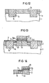
- Trench-shaped recesses 14 defined by a first mask 941 are provided in this, which is preferably done with a selective, vertically oriented, reactive plasma etching. These recesses 14 are then filled with an insulation material 15, for example in the course of a thermal oxidation with SiO 2 , the material projecting beyond the interface 2a being removed again, for example by a further etching process.
- An oxidation step for applying an SiO 2 gate oxide layer 7 follows (FIG. 13).
- a polycrystalline silicon layer 94 is then applied over the entire area, heavily doped with donors and covered by an intermediate oxide layer 91 made of S10 2 .
- the lateral boundaries of the gate 6 and the connected word line are defined by a second mask 92, for example made of photoresist, and structured by a selective, vertically oriented, reactive plasma etching.
- an implantation of donor ions for example arsenic, follows to form the n-type region 3, and optionally an implantation of acceptor ions in order to increase the doping of the layer 2 in a zone 93 below the region 3.
- the end portions 94a of the polycrystalline silicon layer 94 are etched out and refilled with SiO 2 in a thermal oxidation step.
- the gate oxide layer 7 is removed in a vertically oriented reactive plasma etching step, a structure according to FIG. 14 being produced.
- a polycrystalline silicon layer 111 which is heavily doped with donors and then covered with an intermediate oxide layer 112 made of SiO 2 .
- a selective, vertically oriented, reactive plasma etching by means of which, according to a third mask 95, the first drive line including its part 4 contacting the region 3 is structured.
- a reactive plasma etching in which the parts of the polycrystalline silicon layers 94 and 111 lying within the opening 97 (FIG. 16) of a fourth mask 96 as well as the intermediate oxide layers and the gate oxide layer 7 are removed up to the interface 2a.
- the end portions of the strip-shaped polycrystalline silicon layers 94 and 111 opening into the opening 97 are then removed and the resulting recesses are filled with SiO 2 by thermal oxidation.
- the SiO 2 formed within the opening 97 on the interface 2a is then removed in a vertically oriented, reactive plasma etching.
- a layer 131 made of polycrystalline silicon which is initially not doped. It is covered with an intermediate oxide layer 132.
- a fifth mask 98 is attached to this, which has an opening 99, which can be somewhat larger than the opening 97 active plasma etching, the part of the intermediate oxide layer 132, which lies within the opening 99, is removed.
- donor ions for example arsenic ions
- a conductive covering 134 is finally applied, the structure of which is carried out by means of a masking step (sixth mask 100).
- the part of this conductive assignment 134 shown in FIG. 17 can continue in the form of a strip either perpendicular to the image plane of FIG. 17 or parallel to this image plane.
- the individual masks are shown one above the other in FIG. 18 and are identified by different line types.
- the surface-side implantation of the polycrystalline silicon layer 131 with donor ions which is designated by 133, can also be omitted.
- the undoped part of the layer 131, which lies within the opening 99 represents the thin insulating layer 10 from FIG. 1, the thickness of which is approximately of the order of 4000 1. Since the conductive covering 134 is arranged on the part of the layer 131 which lies within the opening 99, a Schottky junction which is operated in the forward direction and which represents the load element 11 (FIG. 1) is formed in the region of 133. The conductive assignment 134 then forms the connection to the connection 12.
- a thin insulating layer 151 preferably made of SiO 2 , with a layer thickness of approximately 30 to 60 i by thermal oxidation on the interface 2a within the opening 97.
- the method step for applying the undoped polycrystalline silicon layer 131 and the intermediate oxide layer 132 covering it follows.
- a fifth mask 98 is then applied and the part of the layer 132 located in the opening 99 is removed by means of a reactive plasma etching step.
- an implantation of donor ions follows in the section of the undoped polycrystalline silicon layer 131 lying within the opening 99, an implantation energy being used such that this section of the layer 131 doped up to the interface with the insulating layer 151 becomes.
- the metallically conductive layer 134 is then applied and structured using the mask 100 shown in FIG. 18. Finally, the connections 12, 5 and 8 are attached again.
- the thin insulating layer 10 from FIG. 1 is formed by the applied SiO 2 layer 151.
- the load element 11 (FIG. 1) also represents the Schottky transition that occurs at the interface of the layers 131 and 134 in this variant of the method.
- the zone 93 of the semiconductor layer 2 is, as already indicated, provided with an additional doping, so that it has a stronger degree of doping than the other parts of the layer 2. This is done by a Prevent npn transistor action between parts 1, 2 and 3. Here, charge carriers that are injected from the semiconductor body 1 into the layer 2 would reach the region 3 and influence the potential on the first drive line.
- a selective, vertically oriented, reactive plasma etching process occurs in several process steps, in which the etching agent consists of a weakly inonized gas, which acts on an etching sample primarily in a direction determined by an applied electric field.
- the etching agent consists of a weakly inonized gas, which acts on an etching sample primarily in a direction determined by an applied electric field.
- a barrier layer insulation can also be used.
- 15 represents an n + -conducting region which extends to the interface 1a between parts 1 and 2.
- the area 15 is doped by diffusion or implantation.
- the semiconductor layer 2 can either be an epitaxial layer, which is deposited on the semiconductor body, or can be understood as a diffusion region of the semiconductor body.
Landscapes
- Engineering & Computer Science (AREA)
- Computer Hardware Design (AREA)
- Semiconductor Memories (AREA)
Applications Claiming Priority (4)
| Application Number | Priority Date | Filing Date | Title |
|---|---|---|---|
| DE2935291A DE2935291A1 (de) | 1979-08-31 | 1979-08-31 | Monolithische statische speicherzelle |
| DE2935291 | 1979-08-31 | ||
| DE2935254 | 1979-08-31 | ||
| DE19792935254 DE2935254A1 (de) | 1979-08-31 | 1979-08-31 | Verfahren zur herstellung einer monolithischen statischen speicherzelle |
Publications (2)
| Publication Number | Publication Date |
|---|---|
| EP0024732A2 true EP0024732A2 (fr) | 1981-03-11 |
| EP0024732A3 EP0024732A3 (fr) | 1983-01-12 |
Family
ID=25780803
Family Applications (1)
| Application Number | Title | Priority Date | Filing Date |
|---|---|---|---|
| EP80105133A Ceased EP0024732A3 (fr) | 1979-08-31 | 1980-08-28 | Cellule à mémoire monolithique statique, procédé pour sa fabrication et procédé pour son opération |
Country Status (1)
| Country | Link |
|---|---|
| EP (1) | EP0024732A3 (fr) |
Cited By (1)
| Publication number | Priority date | Publication date | Assignee | Title |
|---|---|---|---|---|
| EP0055803A3 (en) * | 1981-01-02 | 1983-11-09 | International Business Machines Corporation | Semiconductor memory |
Family Cites Families (4)
| Publication number | Priority date | Publication date | Assignee | Title |
|---|---|---|---|---|
| US3961355A (en) * | 1972-06-30 | 1976-06-01 | International Business Machines Corporation | Semiconductor device having electrically insulating barriers for surface leakage sensitive devices and method of forming |
| US4125854A (en) * | 1976-12-02 | 1978-11-14 | Mostek Corporation | Symmetrical cell layout for static RAM |
| US4122545A (en) * | 1978-01-03 | 1978-10-24 | Sperry Rand Corporation | Memory array of inversion controlled switches |
| US4157269A (en) * | 1978-06-06 | 1979-06-05 | International Business Machines Corporation | Utilizing polysilicon diffusion sources and special masking techniques |
-
1980
- 1980-08-28 EP EP80105133A patent/EP0024732A3/fr not_active Ceased
Cited By (1)
| Publication number | Priority date | Publication date | Assignee | Title |
|---|---|---|---|---|
| EP0055803A3 (en) * | 1981-01-02 | 1983-11-09 | International Business Machines Corporation | Semiconductor memory |
Also Published As
| Publication number | Publication date |
|---|---|
| EP0024732A3 (fr) | 1983-01-12 |
Similar Documents
| Publication | Publication Date | Title |
|---|---|---|
| DE2632036C2 (de) | Integrierte Speicherschaltung mit Feldeffekttransistoren | |
| DE2235801C3 (de) | Monolithischer Festwertspeicher und Verfahren zur Herstellung | |
| DE3117719C2 (fr) | ||
| DE2802141C2 (de) | Halbleiteranordnung | |
| DE3736387A1 (de) | Nicht-fluechtige halbleiterspeichervorrichtung | |
| DE2705503C3 (de) | Halbleiterspeicheranordnung | |
| DE3029125A1 (de) | Halbleiterspeicher | |
| DE2755953C2 (de) | Halbleiteranordnung in Form eines Speichers mit beliebigem Zugriff | |
| DE2621136C2 (de) | Vorprogrammierter Halbleiterspeicher | |
| DE2363089C3 (de) | Speicherzelle mit Feldeffekttransistoren | |
| DE2818783C3 (de) | Datenspeicherzelle | |
| DE2703871C2 (de) | Halbleiterspeicher mit wenigstens einem V-MOS-Transistor | |
| DE3140268A1 (de) | Halbleiteranordnung mit mindestens einem feldeffekttransistor und verfahren zu ihrer herstellung | |
| DE3780298T2 (de) | Nichtfluechtiger speicher mit isoliertem gate ohne dickes oxid. | |
| DE2926417A1 (de) | Dynamische halbleiterspeicherzelle und verfahren zu ihrer herstellung | |
| DE2228931C2 (de) | Integrierte Halbleiteranordnung mit mindestens einem materialverschiedenen Halbleiterübergang und Verfahren zum Betrieb | |
| DE2236510B2 (de) | Monolithisch integrierbare Speicherzelle | |
| DE3153137C2 (fr) | ||
| DE2734354A1 (de) | Speicherelement | |
| DE3330026A1 (de) | Integrierte rs-flipflop-schaltung | |
| DE3871823T2 (de) | Halbleiterspeicheranordnung. | |
| DE2935254A1 (de) | Verfahren zur herstellung einer monolithischen statischen speicherzelle | |
| DE2816949A1 (de) | Monolithisch integrierte halbleiteranordnung und deren verwendung zum aufbau einer speicheranordnung | |
| DE2842334A1 (de) | Halbleiteranordnung | |
| EP0024732A2 (fr) | Cellule à mémoire monolithique statique, procédé pour sa fabrication et procédé pour son opération |
Legal Events
| Date | Code | Title | Description |
|---|---|---|---|
| PUAI | Public reference made under article 153(3) epc to a published international application that has entered the european phase |
Free format text: ORIGINAL CODE: 0009012 |
|
| AK | Designated contracting states |
Designated state(s): FR GB NL |
|
| 17P | Request for examination filed |
Effective date: 19811028 |
|
| PUAL | Search report despatched |
Free format text: ORIGINAL CODE: 0009013 |
|
| AK | Designated contracting states |
Designated state(s): FR GB NL |
|
| STAA | Information on the status of an ep patent application or granted ep patent |
Free format text: STATUS: THE APPLICATION HAS BEEN REFUSED |
|
| 18R | Application refused |
Effective date: 19841215 |
|
| RIN1 | Information on inventor provided before grant (corrected) |
Inventor name: WIEDER, ARMIN, DR. |