EP0024786A2 - Drucker - Google Patents
Drucker Download PDFInfo
- Publication number
- EP0024786A2 EP0024786A2 EP80301463A EP80301463A EP0024786A2 EP 0024786 A2 EP0024786 A2 EP 0024786A2 EP 80301463 A EP80301463 A EP 80301463A EP 80301463 A EP80301463 A EP 80301463A EP 0024786 A2 EP0024786 A2 EP 0024786A2
- Authority
- EP
- European Patent Office
- Prior art keywords
- sheet
- printing apparatus
- paper
- printing
- data
- Prior art date
- Legal status (The legal status is an assumption and is not a legal conclusion. Google has not performed a legal analysis and makes no representation as to the accuracy of the status listed.)
- Granted
Links
Images


Classifications
-
- G—PHYSICS
- G01—MEASURING; TESTING
- G01K—MEASURING TEMPERATURE; MEASURING QUANTITY OF HEAT; THERMALLY-SENSITIVE ELEMENTS NOT OTHERWISE PROVIDED FOR
- G01K7/00—Measuring temperature based on the use of electric or magnetic elements directly sensitive to heat ; Power supply therefor, e.g. using thermoelectric elements
- G01K7/02—Measuring temperature based on the use of electric or magnetic elements directly sensitive to heat ; Power supply therefor, e.g. using thermoelectric elements using thermoelectric elements, e.g. thermocouples
- G01K7/10—Arrangements for compensating for auxiliary variables, e.g. length of lead
- G01K7/12—Arrangements with respect to the cold junction, e.g. preventing influence of temperature of surrounding air
- G01K7/13—Circuits for cold-junction compensation
-
- G—PHYSICS
- G01—MEASURING; TESTING
- G01D—MEASURING NOT SPECIALLY ADAPTED FOR A SPECIFIC VARIABLE; ARRANGEMENTS FOR MEASURING TWO OR MORE VARIABLES NOT COVERED IN A SINGLE OTHER SUBCLASS; TARIFF METERING APPARATUS; MEASURING OR TESTING NOT OTHERWISE PROVIDED FOR
- G01D15/00—Component parts of recorders for measuring arrangements not specially adapted for a specific variable
- G01D15/20—Recording elements for printing with ink or for printing by deformation or perforation of the recording surface, e.g. embossing
-
- G—PHYSICS
- G01—MEASURING; TESTING
- G01D—MEASURING NOT SPECIALLY ADAPTED FOR A SPECIFIC VARIABLE; ARRANGEMENTS FOR MEASURING TWO OR MORE VARIABLES NOT COVERED IN A SINGLE OTHER SUBCLASS; TARIFF METERING APPARATUS; MEASURING OR TESTING NOT OTHERWISE PROVIDED FOR
- G01D15/00—Component parts of recorders for measuring arrangements not specially adapted for a specific variable
- G01D15/28—Holding means for recording surfaces; Guiding means for recording surfaces; Exchanging means for recording surfaces
- G01D15/30—Holding means for recording surfaces; Guiding means for recording surfaces; Exchanging means for recording surfaces for foldable strip charts
-
- G—PHYSICS
- G01—MEASURING; TESTING
- G01D—MEASURING NOT SPECIALLY ADAPTED FOR A SPECIFIC VARIABLE; ARRANGEMENTS FOR MEASURING TWO OR MORE VARIABLES NOT COVERED IN A SINGLE OTHER SUBCLASS; TARIFF METERING APPARATUS; MEASURING OR TESTING NOT OTHERWISE PROVIDED FOR
- G01D18/00—Testing or calibrating apparatus or arrangements provided for in groups G01D1/00 - G01D15/00
- G01D18/002—Automatic recalibration
- G01D18/006—Intermittent recalibration
-
- G—PHYSICS
- G01—MEASURING; TESTING
- G01D—MEASURING NOT SPECIALLY ADAPTED FOR A SPECIFIC VARIABLE; ARRANGEMENTS FOR MEASURING TWO OR MORE VARIABLES NOT COVERED IN A SINGLE OTHER SUBCLASS; TARIFF METERING APPARATUS; MEASURING OR TESTING NOT OTHERWISE PROVIDED FOR
- G01D3/00—Indicating or recording apparatus with provision for the special purposes referred to in the subgroups
- G01D3/028—Indicating or recording apparatus with provision for the special purposes referred to in the subgroups mitigating undesired influences, e.g. temperature, pressure
- G01D3/032—Indicating or recording apparatus with provision for the special purposes referred to in the subgroups mitigating undesired influences, e.g. temperature, pressure affecting incoming signal, e.g. by averaging; gating undesired signals
-
- G—PHYSICS
- G01—MEASURING; TESTING
- G01D—MEASURING NOT SPECIALLY ADAPTED FOR A SPECIFIC VARIABLE; ARRANGEMENTS FOR MEASURING TWO OR MORE VARIABLES NOT COVERED IN A SINGLE OTHER SUBCLASS; TARIFF METERING APPARATUS; MEASURING OR TESTING NOT OTHERWISE PROVIDED FOR
- G01D3/00—Indicating or recording apparatus with provision for the special purposes referred to in the subgroups
- G01D3/028—Indicating or recording apparatus with provision for the special purposes referred to in the subgroups mitigating undesired influences, e.g. temperature, pressure
- G01D3/036—Indicating or recording apparatus with provision for the special purposes referred to in the subgroups mitigating undesired influences, e.g. temperature, pressure on measuring arrangements themselves
- G01D3/0365—Indicating or recording apparatus with provision for the special purposes referred to in the subgroups mitigating undesired influences, e.g. temperature, pressure on measuring arrangements themselves the undesired influence being measured using a separate sensor, which produces an influence related signal
-
- G—PHYSICS
- G01—MEASURING; TESTING
- G01D—MEASURING NOT SPECIALLY ADAPTED FOR A SPECIFIC VARIABLE; ARRANGEMENTS FOR MEASURING TWO OR MORE VARIABLES NOT COVERED IN A SINGLE OTHER SUBCLASS; TARIFF METERING APPARATUS; MEASURING OR TESTING NOT OTHERWISE PROVIDED FOR
- G01D9/00—Recording measured values
- G01D9/28—Producing one or more recordings, each recording being of the values of two or more different variables
- G01D9/32—Producing one or more recordings, each recording being of the values of two or more different variables there being a common recording element for two or more variables
- G01D9/34—Producing one or more recordings, each recording being of the values of two or more different variables there being a common recording element for two or more variables the variables being recorded in a predetermined sequence
-
- G—PHYSICS
- G01—MEASURING; TESTING
- G01K—MEASURING TEMPERATURE; MEASURING QUANTITY OF HEAT; THERMALLY-SENSITIVE ELEMENTS NOT OTHERWISE PROVIDED FOR
- G01K1/00—Details of thermometers not specially adapted for particular types of thermometer
- G01K1/02—Means for indicating or recording specially adapted for thermometers
- G01K1/026—Means for indicating or recording specially adapted for thermometers arrangements for monitoring a plurality of temperatures, e.g. by multiplexing
Definitions
- the present invention relates to methods of and apparatus for data recording and the like, being more particularly directed to the recording of data such as that produced during measurement, control or production monitoring and similar operations, and documenting the recorded information in a format suitable for direct use in logs and reports in related usages.
- the parameters being recorded or logged for display to the operator be summarized in a form suitable for ultimate presentation in a written report or the like.
- a tabular form is often desirable.
- the data has been extracted from the recorder charts and summarized or transcribed manually; or, in more elaborate systems, the data has been transmitted to a computer system in a different part of the plant to be summarized for inclusion in a report.
- An object of the present invention is to provide a new and improved data recording apparatus and method that lend themselves to utilization particularly, though not exclusively, in industrial plant environments, and that obviate the above-mentioned and other problems, providing for the clear presentation of data which has been recorded in the recent past such that an operator can readily observe current values and trends, and in a digital, tabular format suitable for direct insertion in reports.
- the invention embraces printing apparatus for use with impact-sensitive paper having, in combination, means for mounting the paper as a continous longitudinally extending substantially flat sheet to be directly viewed from one face thereof, print head means disposed at a predetermined location on the other face of the sheet, and means for causing the print head means to impact against the said other face along transverse lines at said predetermined location to produce visible printing on the said one face.
- the printing apparatus may include means for moving the paper longitudinally after a transverse line is printed to permit immediate viewing of the data just printed.
- the said pre- determined location is near the bottom thereof, and means is provided for thereafter guiding the sheet downward to a receiving tray inclined at an acute angle td the horizontal to enable the automatic folding storage of the paper as it drops a limited vertical distance into the tray.
- the downward movement of the sheet may be controlled by guide and static-removing bar means.
- the printing apparatus may include optical sensing means movable with the said print head means, and cooperative with transverse optical fence means comprising a central portion having alternating transparent and opaque portions for enabling optical sensing of the location of the print head means relative to the position of the sheet to be printed, and end portions respectively comprising a transparent portion, and an opaque portion for enabling optical sensing determination that the print head means is at an end of the printed portion of a transverse line along said sheet and at which margin of the sheet.
- the printing apparatus may be provided with stepping motor means for longitudinally advancing the paper sheet one line to the next, and pulse-width modulated drive circuit means for operating the stepping motor means with lower power consumption when the same is stationary than when moving, thereby to permit the same to be operated at higher than rated torque while not exceeding rated time-averaged power.
- the printing apparatus may also include sensing means for monitoring electrical signals to be recorded and generating digital voltage data corresponding to the same, and data acquistion means comprising microprocessor means for receiving said digital voltage data and converting the same into desired engineering data for printing.
- a light source and optical sensor 1' mounted rearwardly with the print head 1, detects, as the head transversely tranverses the apparatus, alternate transparent and opaque vertical lines on a fixed transverse strip 8, extending beyond the width of the printed page, and serving as an optical fence, with one end completely opaque, and the other end completely transparent.
- a special electronic circuit detects each transition from transparent to opaque as a potential print position, and the printer logic will cause the appropriate character to be printed.
- an associated control circuit will continue to print the next line of data or turn off the motor if there is no further data to be printed.
- the printer logic By sensing whether the strip is completely transparent or completely opaque, the printer logic is informed whether the print head 1 is at the left or right margin of the page so that, unlike other prior printing apparatus, there is no need to have separate sensors to determine when the print head 1 is at a margin, and to determine which margin.
- the control logic is designed such that printing can occur with the print 1 travelling in either transverse direction, so that it is not necessary to bring the print head 1 back to the left margin each time before starting a new line.
- the construction of the invention thus eliminates the typical carriage return operation of most printers. If the next line to be printed is already available, the motor 4 driving the print head 1 does not stop when a margin is detected, but it continues to drive the print head 1, and the slider-pin mechanism 6 automatically reverses the direction of the print head 1. With this type of mechanism, the next complete line to be printed is stored in the hereinafter described microprocessor memory before the printing operation of that line is started.
- Exemplary components for this system are, for example, the Model IPM 129 print head of Victor Comptometer Corporation, which includes an optical sensor.
- Paper moves continuously from the paper supply tray 10 through paper guides 9. It then passes between the platen 3 and the print head 1, as before described, vertically upward as a substantially flat sheet through a paper tension mechanism such as side friction clips 11 to the set of feed tractors 12, 12' which pull the paper from the feed tray when a new line has been printed and position it at the proper location for the next line.
- the print head 1 and the platen 3 must be oriented so that the motion of the flat sheet of paper by one vertical line space will move the previous printed line into view. This permits an observer immediately to view the current data which has just been printed, unlike other types of printers.
- the tension clip.s or other mechanism 11 In order to maintain even line spacing, the tension clip.s or other mechanism 11 must maintain proper and uniform tension on the paper at the bottom of the apparatus, the same also preventing the paper from moving in the left-to-right direction and thereby providing a printed page with the desired vertical column alignment.
- the paper tractors 12, 12' are operated by a single stepping motor 13 through belt 14 and pulley drive mechanism 15.
- printer mechanism Details of the printer mechanism, carriage controls, sensor and other circuit and constructional details are not presented in order to avoid detracting from the novel features of the invention with well-known mechanisms; but reference to other suitable constructions is made, for example, to the Kaye Instruments "Digistrip Recorder Installation, Operation and Maintenance Manual", dated April 1978.
- the electrical circuit to drive the stepping motor 13 has been designed in accordance with the best mode of the invention to minimize the power dissipated, thereby minimizing the temperature rise of the motor and the interior of the semi-sealed enclosure.
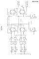
- the stepping motor drive circuit preferably operates under the principle of pulse-width modulation of the voltage across the stepping motor, as later described in connection with the preferred form of Figure 2.
- a very low duty cycle pulse train is used to provide detent action of the mechanism.
- a full duty cycle with a voltage which is higher than--more than twice--the rated voltage of the stepping motor is used to provide maximum and higher-than-rated torque.
- the stepping motor 13 is accordingly operated with lower power consumption when stationary than when moving to attain the above results. Another feature of this circuit allows positioning of the page to be maintained during a power-off/power-on sequence. This facilitates the pagination of the paper even if a power failure occurs.
- a typical stepping motor suitable for use in accordance with the invention is divided into two sections, each of which has two sets of windings.
- the first section contains windings 37 and 39, and the second section, windings 41 and 43.
- Each winding is driven by a drive circuit D the output of which, is the collector of a transistor in the common-emitter configuration. When each drive circuit D is activated, current flows from the supply voltage V D through the corresponding motor winding and through the output transistor to ground.
- the circuit of Figure 2 is placed in its quiescent or non-stepping state by the reset input to edge-triggered flip-flop 30, or as a natural result of the completion of a step operation.
- Flip-flop 30 serves as a master control in association with oscillators 34 and 35 and resets further flip-flops 31, 32 and 33. While in the quiescent state, the flip-flop 30 is in the off state, and, in turn, resets flip-flops 31, 32 and 33, and resets oscillator 34 and enables oscillator 35.
- Oscillator 35 has a time asymmetrical output which is low for 10 microseconds (psec) and high for 500 psec. In the quiescent state, only windings 37 and 41 are activated.
- V D can be two or more times the rated voltage of the stepping motor without causing overeating.
- Oscillator 34 clocks respective flip-flops 31 and 32 at 31Q through the necessary sequence of outputs. After four oscillator pulses from 34Q, flip-flop 33 turns on as shown at 33Q. After an additonal four oscillator pulses, flip-flop 33 turns off, in turn turning off master control flip-flop 30 and placing the control circuit in the quiescent state once again.
- the outputs of gates 36 and 40, respectively operating through the drivers D connected with windings 37 and 41, are shown at 36 Out and 40 Out in Figure 3, and the outputs of circuits 38 and 42, respectively connecting the Q outputs of flip-flops 31 and 32 to operate the drivers D connected to windings 39 and 43, are illustrated at 38 Out and 42 Out, respectively.
- the reset input to the master control flip-flop 30 is used to prevent partial stepping of the circuit when power is turned on by immediately placing the circuit in the quiescent state, thus preventing stepping when power is turned on and, in turn, facilitating the pagination process whereby the paper is held in the same position after a power failure as when power failed.
- the apparatus of the present invention embodies special means to assure a proper folding of the paper within the limited dimensions of the enclosure.
- These means include an upper electro-static discharge and guide bar 16 and a paper receiver tray 17 which, in accordance with the invention, must be positioned at a rather critical angle inclined to the horizontal of between substantially 10 and 20 0 , in order to fold the paper properly with a very limited vertical drop of less than, say, 7 inches ' , more or less.
- a feature which is not essential to the operation of the apparatus, but which adds a desirable character of low noise, is a platen 3 constructed of a composite of alternating metallic strips and vibration-damping material.
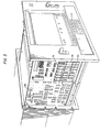
- the electronics to control all printer operations is shown on a single printed circuit board 18 containing a microprocessor and all of the required logic and memory.
- the printer mechanism can, of course, operate independently of the data acquisition portion of the apparatus, if so desired.
- the data acquisition portion on printed circuit board 50 has an independent microprocessor which controls all operations other than the printing of the data.
- three types of memory are employed in the data acquisition logic.
- the read- only memory portion 51 is used to store permanently the programmed instructions to direct the data aquisition functions, and also contains tables which are used for conversion of digital voltage data into the proper engineering data.
- a second portion of memory 52 called non-volatile random access memory is used to store user-programmed parameters such as the types of input, the frequency of printing, acceptable limits of data and indentifying headers to be printed at the top of each page.
- the third type of memory 53 is called random access memory and is used to store the real-time data being processed from the analog inputs to the system, as is well-known.
- the overall structure of the microprocessor logic on printed circuit board 50 is preferably directed by a "task manager" of the type described in an article entitled “A Task-Scheduling Executive Program for Microcomputer Systems” by David A. Townzen, appearing in Computer Design, June, 1977, pp. 194-202.
- This task manager is an efficient means of controlling task priorities so that a more important task of higher priority will temporarily interrupt a task of lesser priority in order to provide service on a real-time basis.
- Suitable microprocessor apparatus is the type 8085 manufactured by Intel Corporation, with memory of the types 2716, 2114 and 5101 of Intel Corporation, or other equally well-known microprocessor apparatus.
- a resulting page of summary data directly useable for reports and the like and stemming from the microprocessor-printer of the invention 8t x 11 inch fanfold paper, for example
- up to five lines may be made available on the sheet for customized header indentification, each line having 128 characters corresponding to a field of 8 characters for each of 16 channel postions.
- Conventional customer-programmed alpha-numeric messages can be introduced to a conventional keyboard 54, located at the bottom of the front panel of Figure 5, for example, such that the microprocessor enables the automatic printing of the same at the top of every new fanfold page sheet.
- Suitable keyboard control is provided by a Brady Corporation Lite Touch (TM) panel operating in conjunction with an Intel Corporation type 8279 keyboard interface module.
- the apparatus may provide one to four lines of data, for example, to be printed in normal enginer- ing units as a block, with a blank line inserted after each block to separate the data corresponding to a single scan, if desired.
- the program may enable the paper automatically to advance to the top of the next page for header printing.
- the header printout may also automatically include a day's register printout in the time field locations.
- Alarms may be indicated by an asterisk printed in the data field of the alarm channel, and the types of printed data may be indentified by an alphabetic character representing the appropriate engingeering units, and matching that used on the front panel display, printed as the last character in each channel's data field. Not counting header and margin space, approxmately 40 lines per page can be available with the above-described fanfold paper for recording data. With 16 channels printed per line, 96,000 readings can be recorded on a typical stack of paper having about 150 pages.
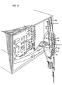
- An analog-multiplexer 23, shown in figure 4, is provided with one extra switch SW1 with a known zero voltage input.
- the microprocessor logic is designed, as well know, to read that extra input periodically during the multiplexing sequence, convert same to digital form by means of an analog to digital converter 19, and store the value as an offset which must be subtracted from the other input voltages. In order to obtain greater stability of the zero level, several successive readings of this zero input are maintained in memory and averaged. The average offset is subtracted from all other input signals. Suitable averaging and subtracting is performed by the microprocessor.
- Figure 4 also illustrates an improvement in the art of uniform temperature references for thermocouple inputs such as that described in U.S. Patent 3,648,523.
- the sensor system of Figure 4 employs a bar 21 of a highly thermal conductive material, such as aluminum, having opposing flat surfaces provided with a thin insulating coating on the surace 21', such as aluminum oxide, and which is in intimate thermal contact with the printed circuit board mounting screw terminal shafts 25 of all of the input terminals 22.
- the design permits the insertion of these terminals into a printed circuit board 23 and the insertion of a temperature sensor Rl into the highly conductive bar so that all terminals, as well as sensor R1, are maintained at very nearly the same or equal temperature.
- the sensor which monitors the terminal temperature is read as a separate input.
- a single temperature-sensitive resistor Rl made of a material having known resistivity versus temperature characteristics is placed in series with a manually-adjustable resistor R2.
- a precision voltage V maintains a constant voltage across the series connection of the two resistors.
- the other resistor R2 is manually adjusted to provide a pre-determined value of voltage across the temperature-sensitive resistor. This single adjustment assures that the proper value of voltage will be produced across the temperature sensitive resistor at all temperatures within the operating range of the apparatus.
- the microprocessor logic before described automatically adds the proper reference voltage for each type of thermocouple corresponding to the temperature of the input terminals as determined by reading the value of voltage appearing across the temperature-sensitive resistor.
Landscapes
- Physics & Mathematics (AREA)
- General Physics & Mathematics (AREA)
- Recording Measured Values (AREA)
- Handling Of Sheets (AREA)
- Confectionery (AREA)
- Power Steering Mechanism (AREA)
- Time Recorders, Dirve Recorders, Access Control (AREA)
- Optical Recording Or Reproduction (AREA)
- Diaphragms For Electromechanical Transducers (AREA)
- Paper (AREA)
- Developing Agents For Electrophotography (AREA)
- Surgical Instruments (AREA)
- Impact Printers (AREA)
- Ink Jet (AREA)
- Handling Of Continuous Sheets Of Paper (AREA)
- Character Spaces And Line Spaces In Printers (AREA)
- Accessory Devices And Overall Control Thereof (AREA)
- Information Retrieval, Db Structures And Fs Structures Therefor (AREA)
Priority Applications (1)
| Application Number | Priority Date | Filing Date | Title |
|---|---|---|---|
| AT80301463T ATE21768T1 (de) | 1979-09-04 | 1980-05-02 | Drucker. |
Applications Claiming Priority (2)
| Application Number | Priority Date | Filing Date | Title |
|---|---|---|---|
| US06/071,947 US4329693A (en) | 1979-09-04 | 1979-09-04 | Method of and apparatus for data recording and the like |
| US71947 | 1979-09-04 |
Related Child Applications (2)
| Application Number | Title | Priority Date | Filing Date |
|---|---|---|---|
| EP85100017A Division EP0156099A3 (de) | 1979-09-04 | 1980-05-02 | Verfahren und Vorrichtung zur Datenaufzeichnung |
| EP85100017.4 Division-Into | 1985-01-02 |
Publications (3)
| Publication Number | Publication Date |
|---|---|
| EP0024786A2 true EP0024786A2 (de) | 1981-03-11 |
| EP0024786A3 EP0024786A3 (en) | 1982-03-31 |
| EP0024786B1 EP0024786B1 (de) | 1986-08-27 |
Family
ID=22104598
Family Applications (2)
| Application Number | Title | Priority Date | Filing Date |
|---|---|---|---|
| EP85100017A Withdrawn EP0156099A3 (de) | 1979-09-04 | 1980-05-02 | Verfahren und Vorrichtung zur Datenaufzeichnung |
| EP80301463A Expired EP0024786B1 (de) | 1979-09-04 | 1980-05-02 | Drucker |
Family Applications Before (1)
| Application Number | Title | Priority Date | Filing Date |
|---|---|---|---|
| EP85100017A Withdrawn EP0156099A3 (de) | 1979-09-04 | 1980-05-02 | Verfahren und Vorrichtung zur Datenaufzeichnung |
Country Status (15)
| Country | Link |
|---|---|
| US (1) | US4329693A (de) |
| EP (2) | EP0156099A3 (de) |
| JP (1) | JPS5637512A (de) |
| AT (1) | ATE21768T1 (de) |
| AU (1) | AU535217B2 (de) |
| CA (1) | CA1159789A (de) |
| DE (1) | DE3071716D1 (de) |
| DK (1) | DK288680A (de) |
| HK (1) | HK16688A (de) |
| IE (1) | IE50348B1 (de) |
| IL (1) | IL59847A (de) |
| MX (1) | MX148947A (de) |
| NO (1) | NO801682L (de) |
| NZ (1) | NZ193443A (de) |
| SG (1) | SG94287G (de) |
Families Citing this family (8)
| Publication number | Priority date | Publication date | Assignee | Title |
|---|---|---|---|---|
| JPH0611561B2 (ja) * | 1983-05-19 | 1994-02-16 | シャープ株式会社 | 用紙送り装置のステップモータ制御装置 |
| EP0183356B1 (de) * | 1984-10-02 | 1991-07-03 | Fujitsu Limited | Drucker mit einer von der Vorderseite einführbare Papiervorschubeinrichtung |
| DE3611772C2 (de) * | 1986-04-08 | 1995-05-24 | Metrawatt Gmbh Gossen | Verfahren zum Festlegen eines momentanen Meßwertes |
| US4686540A (en) * | 1986-04-15 | 1987-08-11 | Microdynamics, Inc. | Compact plotter for generation of accurate plotted images of long length |
| JPH023851U (de) * | 1989-03-23 | 1990-01-11 | ||
| WO1992020851A1 (en) * | 1991-05-10 | 1992-11-26 | Organ Needle Co., Ltd. | Sewing machine needle and method of manufacturing same |
| DE4339783A1 (de) * | 1993-11-18 | 1995-06-01 | Mannesmann Ag | Antriebsanordnung für einen Prozeßschreiber |
| US7729004B2 (en) * | 2005-07-29 | 2010-06-01 | Hewlett-Packard Development Company, L.P. | Print job manifest |
Family Cites Families (21)
| Publication number | Priority date | Publication date | Assignee | Title |
|---|---|---|---|---|
| US1929367A (en) * | 1930-05-19 | 1933-10-03 | Siemens Ag | Recording measuring instruments |
| BE463551A (de) * | 1944-01-12 | |||
| US3193837A (en) * | 1958-09-11 | 1965-07-06 | Fischer & Porter Co | Digital data recorder |
| NL263314A (de) * | 1960-04-07 | |||
| FR1327170A (fr) * | 1962-04-03 | 1963-05-17 | Appareil pour ranger les bandes de papier produites par les machines imprimantes de bureau | |
| US3388404A (en) * | 1966-08-16 | 1968-06-11 | Eugene S. Bush | Information recording device |
| US3787878A (en) * | 1972-07-03 | 1974-01-22 | Beckman Instruments Inc | Dual channel strip chart recorder |
| US3795013A (en) * | 1972-10-13 | 1974-02-26 | Honeywell Inc | Recording system having digital control for controlling recording medium movement |
| US3971041A (en) * | 1973-10-03 | 1976-07-20 | Esterline Corporation | Chart recorder using a fixed thermal print head |
| DE2355361A1 (de) * | 1973-11-06 | 1975-05-07 | Bodenseewerk Perkin Elmer Co | Vorrichtung zum abgleich der digitalen anzeige eines analogen signals |
| US3854145A (en) * | 1973-11-28 | 1974-12-10 | Foxboro Co | Strip-chart recording apparatus |
| US3921178A (en) * | 1974-02-11 | 1975-11-18 | Charles F Weisgerber | Time utilization monitor |
| DE2452746A1 (de) * | 1974-11-07 | 1976-05-20 | Peter Hans | Verfahren zur auswertung von temperaturmessungen |
| FR2291500A1 (fr) * | 1974-11-13 | 1976-06-11 | Kernforschungsanlage Juelich | Appareil pour enregistrer des valeurs de mesure transformees en un signal electrique numerique |
| US4039127A (en) * | 1976-02-09 | 1977-08-02 | Mobil Oil Corporation | Continuous plotter |
| DE2703014A1 (de) * | 1977-01-26 | 1978-07-27 | Wallner Franz | Einrichtung zum nachfuehren der nullage und des schreibbereiches der schreibzeiger schreibender registriergeraete mit querverschiebungen des registrierpapiers |
| US4107697A (en) * | 1977-08-03 | 1978-08-15 | Otis Engineering Corporation | Pressure recorder with power conservation means |
| JPS5479085A (en) * | 1977-12-05 | 1979-06-23 | Matsushita Electric Ind Co Ltd | Temperature measuring apparatus |
| US4208137A (en) * | 1978-01-16 | 1980-06-17 | Ncr Corporation | Position sensing for matrix printer |
| US4147061A (en) * | 1978-07-07 | 1979-04-03 | Avco Corporation | Thermocouple reference junction calibrator |
| US4172258A (en) * | 1978-07-28 | 1979-10-23 | Honeywell Inc. | Multicolor multipoint recorder |
-
1979
- 1979-09-04 US US06/071,947 patent/US4329693A/en not_active Expired - Lifetime
-
1980
- 1980-04-10 CA CA000349556A patent/CA1159789A/en not_active Expired
- 1980-04-15 NZ NZ193443A patent/NZ193443A/en unknown
- 1980-04-16 IL IL59847A patent/IL59847A/xx unknown
- 1980-05-02 DE DE8080301463T patent/DE3071716D1/de not_active Expired
- 1980-05-02 EP EP85100017A patent/EP0156099A3/de not_active Withdrawn
- 1980-05-02 AT AT80301463T patent/ATE21768T1/de not_active IP Right Cessation
- 1980-05-02 EP EP80301463A patent/EP0024786B1/de not_active Expired
- 1980-05-07 AU AU58189/80A patent/AU535217B2/en not_active Ceased
- 1980-06-05 NO NO801682A patent/NO801682L/no unknown
- 1980-06-11 IE IE1208/80A patent/IE50348B1/en unknown
- 1980-07-04 DK DK288680A patent/DK288680A/da not_active Application Discontinuation
- 1980-07-11 MX MX183135A patent/MX148947A/es unknown
- 1980-08-13 JP JP11157080A patent/JPS5637512A/ja active Pending
-
1987
- 1987-10-29 SG SG942/87A patent/SG94287G/en unknown
-
1988
- 1988-03-03 HK HK166/88A patent/HK16688A/xx unknown
Also Published As
| Publication number | Publication date |
|---|---|
| NO801682L (no) | 1981-03-05 |
| NZ193443A (en) | 1984-03-30 |
| EP0024786A3 (en) | 1982-03-31 |
| EP0156099A3 (de) | 1986-08-13 |
| DK288680A (da) | 1981-03-05 |
| ATE21768T1 (de) | 1986-09-15 |
| HK16688A (en) | 1988-03-11 |
| IL59847A (en) | 1984-07-31 |
| IE801208L (en) | 1981-03-04 |
| SG94287G (en) | 1988-05-06 |
| US4329693A (en) | 1982-05-11 |
| DE3071716D1 (en) | 1986-10-02 |
| JPS5637512A (en) | 1981-04-11 |
| AU535217B2 (en) | 1984-03-08 |
| CA1159789A (en) | 1984-01-03 |
| MX148947A (es) | 1983-07-20 |
| IE50348B1 (en) | 1986-04-02 |
| IL59847A0 (en) | 1980-06-30 |
| EP0156099A2 (de) | 1985-10-02 |
| AU5818980A (en) | 1981-03-12 |
| EP0024786B1 (de) | 1986-08-27 |
Similar Documents
| Publication | Publication Date | Title |
|---|---|---|
| EP0024786B1 (de) | Drucker | |
| EP0489909B1 (de) | Kompensation des parasitären widerstands für thermodrucker | |
| US3840878A (en) | Dual mode thermal recorder | |
| CA1291366C (en) | Transverse printing control system for multiple print/cartridge printer | |
| US4359747A (en) | Thermocouple recorder | |
| CA1126407A (en) | Position sensing for matrix printer | |
| US3971041A (en) | Chart recorder using a fixed thermal print head | |
| US4359751A (en) | Stepper motor for data recorder | |
| US4359746A (en) | Zero level correction apparatus | |
| CA1171015A (en) | Method of and apparatus for data recording and the like | |
| CA1170204A (en) | Printing apparatus with print head sensing means | |
| JP2988308B2 (ja) | テーププリンタ装置 | |
| JPS6184264A (ja) | 印字器への単一シート引込みのための装置 | |
| US4642657A (en) | Recorder | |
| EP0168474B1 (de) | Positionsanzeige für ein elektrisch gesteuertes gerät, insbesondere für einen drucker | |
| US3573843A (en) | Data and time recorder | |
| US4719473A (en) | Recording apparatus | |
| CA2103602C (en) | Chart recorder | |
| CA1306119C (en) | Electronic clinical thermometer equipped with printer | |
| US4409597A (en) | Line printer for recording analog signals | |
| US5025265A (en) | Method and apparatus for increasing visibility of trend lines on strip chart recorders | |
| JP2659571B2 (ja) | 紙送り装置 | |
| EP0165563B1 (de) | Drucker mit Thermodruckkopf | |
| JPH0230444B2 (de) | ||
| JP2667091B2 (ja) | ラベル印字装置 |
Legal Events
| Date | Code | Title | Description |
|---|---|---|---|
| PUAI | Public reference made under article 153(3) epc to a published international application that has entered the european phase |
Free format text: ORIGINAL CODE: 0009012 |
|
| AK | Designated contracting states |
Designated state(s): AT BE CH DE FR GB IT LU NL SE |
|
| 17P | Request for examination filed |
Effective date: 19810810 |
|
| PUAL | Search report despatched |
Free format text: ORIGINAL CODE: 0009013 |
|
| RHK1 | Main classification (correction) |
Ipc: G01D 9/34 |
|
| AK | Designated contracting states |
Designated state(s): AT BE CH DE FR GB IT LU NL SE |
|
| GRAA | (expected) grant |
Free format text: ORIGINAL CODE: 0009210 |
|
| AK | Designated contracting states |
Kind code of ref document: B1 Designated state(s): AT BE CH DE FR GB IT LI LU NL SE |
|
| REF | Corresponds to: |
Ref document number: 21768 Country of ref document: AT Date of ref document: 19860915 Kind code of ref document: T |
|
| REF | Corresponds to: |
Ref document number: 3071716 Country of ref document: DE Date of ref document: 19861002 |
|
| ET | Fr: translation filed | ||
| ITF | It: translation for a ep patent filed | ||
| PG25 | Lapsed in a contracting state [announced via postgrant information from national office to epo] |
Ref country code: AT Effective date: 19870502 |
|
| PG25 | Lapsed in a contracting state [announced via postgrant information from national office to epo] |
Ref country code: SE Effective date: 19870503 |
|
| PG25 | Lapsed in a contracting state [announced via postgrant information from national office to epo] |
Ref country code: LU Free format text: LAPSE BECAUSE OF NON-PAYMENT OF DUE FEES Effective date: 19870531 Ref country code: LI Effective date: 19870531 Ref country code: CH Effective date: 19870531 |
|
| PLBE | No opposition filed within time limit |
Free format text: ORIGINAL CODE: 0009261 |
|
| STAA | Information on the status of an ep patent application or granted ep patent |
Free format text: STATUS: NO OPPOSITION FILED WITHIN TIME LIMIT |
|
| 26N | No opposition filed | ||
| BERE | Be: lapsed |
Owner name: KAYE INSTRUMENTS INC. Effective date: 19870531 |
|
| PG25 | Lapsed in a contracting state [announced via postgrant information from national office to epo] |
Ref country code: NL Effective date: 19871201 |
|
| NLV4 | Nl: lapsed or anulled due to non-payment of the annual fee | ||
| REG | Reference to a national code |
Ref country code: CH Ref legal event code: PL |
|
| PG25 | Lapsed in a contracting state [announced via postgrant information from national office to epo] |
Ref country code: GB Effective date: 19880502 |
|
| GBPC | Gb: european patent ceased through non-payment of renewal fee | ||
| PG25 | Lapsed in a contracting state [announced via postgrant information from national office to epo] |
Ref country code: FR Free format text: LAPSE BECAUSE OF NON-PAYMENT OF DUE FEES Effective date: 19890131 |
|
| PG25 | Lapsed in a contracting state [announced via postgrant information from national office to epo] |
Ref country code: DE Effective date: 19890201 |
|
| REG | Reference to a national code |
Ref country code: FR Ref legal event code: ST |
|
| PG25 | Lapsed in a contracting state [announced via postgrant information from national office to epo] |
Ref country code: BE Effective date: 19890531 |
|
| EUG | Se: european patent has lapsed |
Ref document number: 80301463.8 Effective date: 19880330 |