EP0024862A2 - Videogerät, mit dem ausgewählte Farben nebeneinander dargestellt werden können - Google Patents
Videogerät, mit dem ausgewählte Farben nebeneinander dargestellt werden können Download PDFInfo
- Publication number
- EP0024862A2 EP0024862A2 EP80302832A EP80302832A EP0024862A2 EP 0024862 A2 EP0024862 A2 EP 0024862A2 EP 80302832 A EP80302832 A EP 80302832A EP 80302832 A EP80302832 A EP 80302832A EP 0024862 A2 EP0024862 A2 EP 0024862A2
- Authority
- EP
- European Patent Office
- Prior art keywords
- colour
- signals
- segment
- composing
- transition
- Prior art date
- Legal status (The legal status is an assumption and is not a legal conclusion. Google has not performed a legal analysis and makes no representation as to the accuracy of the status listed.)
- Withdrawn
Links
Images




Classifications
-
- B—PERFORMING OPERATIONS; TRANSPORTING
- B44—DECORATIVE ARTS
- B44D—PAINTING OR ARTISTIC DRAWING, NOT OTHERWISE PROVIDED FOR; PRESERVING PAINTINGS; SURFACE TREATMENT TO OBTAIN SPECIAL ARTISTIC SURFACE EFFECTS OR FINISHES
- B44D3/00—Accessories or implements for use in connection with painting or artistic drawing, not otherwise provided for; Methods or devices for colour determination, selection, or synthesis, e.g. use of colour tables
- B44D3/003—Methods or devices for colour determination, selection or synthesis, e.g. use of colour tables
-
- G—PHYSICS
- G09—EDUCATION; CRYPTOGRAPHY; DISPLAY; ADVERTISING; SEALS
- G09G—ARRANGEMENTS OR CIRCUITS FOR CONTROL OF INDICATING DEVICES USING STATIC MEANS TO PRESENT VARIABLE INFORMATION
- G09G5/00—Control arrangements or circuits for visual indicators common to cathode-ray tube indicators and other visual indicators
- G09G5/02—Control arrangements or circuits for visual indicators common to cathode-ray tube indicators and other visual indicators characterised by the way in which colour is displayed
-
- H—ELECTRICITY
- H04—ELECTRIC COMMUNICATION TECHNIQUE
- H04N—PICTORIAL COMMUNICATION, e.g. TELEVISION
- H04N9/00—Details of colour television systems
- H04N9/64—Circuits for processing colour signals
- H04N9/74—Circuits for processing colour signals for obtaining special effects
Definitions
- This invention relates to a video apparatus which allows the effect of juxtaposed colour patterns to be visualised.
- the invention relates particularly, but not exclusively, to an apparatus which simulates the decor of a room and permits the user to experiment with a complete range of colour combinations.
- Tri-colour television type apparatus is of course well known per se. Systems are known in which coloured images are synthesised and displayed by a tri-colour tube. However, I am not aware of any prior proposal to generate a standard picture and enable a user to vary at will the colour (hue, density and saturation) of given areas of the picture.
- a video apparatus comprises:
- the segments are chosen to represent part of a room in which (at least) two walls, floor and ceiling may be shown in different colours.
- the colour composing means may comprise a plurality of composers each having manually operable controls for setting the hue, saturation and black level for one desired colour.
- each colour may be set by a preset plug-in module.
- the apparatus produces a display on a conventional tri-colour television-type tube.
- the circuitry to be described is arranged to produce a stylised perspective image of part of a room.
- the image comprises areas A-E respectively representing a first wall, ceiling, second wall, floor and skirting.
- This image may be modified to include a door F (Fig. 1B) or a window with curtain G (Fig. 1C).
- the apparatus enables each of the areas A-G to be displayed in any desired colour, whereby the effects of proposed decorating schemes may be appreciated and judged by the user.
- the door architrave and window frame are displayed in the same colour as the skirting area E, and the window itself is displayed as black.
- the apparatus includes a number of colour composer circuits 10. Three of these are shown, but it will be appreciated that any suitable.number may be provided; eight has been found suitable.
- Each colour composer circuit 10 gives an analog output defining a given colour (i.e. a given combination of hue, saturation and black) in the form of red, blue and green (R,B,G) signals on lines 12.
- Each colour composer circuit lO may have as shown manually operable controls for setting each of hue, saturation (white) and black.
- the colour composer circuit 10 may be in the form of a plug-in module defining a given colour, with the controls preset.
- the translation module of the circuits lO which provides R ,B, G signals corresponding to the control setting is described in greater detail below.
- the circuitry of Fig. 2 also includes colour selectors 11 for each area of the display, in this embodiment seven selectors 12 corresponding to the areas A- G .
- Each colour selector 12 comprises a switch arranged to receive the R,B,G signals for each of the colours 1- N and to give an output consisting of the R,B,G signals of a selected one colour.
- the selected colour signals for the areas A-G are supplied to a gating and switching unit 14 which has the function of gating these signals to the red, blue and green inputs of a video display unit (v.d.u.) which is not shown in the drawings.
- the v.d.u. is a conventional tri-colour television-type display operating with a 1:1 interlaced raster scan.
- a normal European standard 625 line 50 Hz display may be used.
- a high resolution is not required and 525 or fewer lines may be used.
- the v.d.u. screen is suitably mounted within a box for viewing through a spaced window, to prevent ambient light falling on the screen, thereby desaturating the colours and reducing contrast.
- this gates the selected R,B,G signals to the v.d.u. inputs under the control of switching signals at inputs 16 and mode (i.e. the picture format of Fig. lA, lB or 1C) selected by switch 18.
- the switching signals are supplied to inputs 16 by the circuitry of Fig. 4.
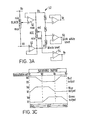
- the circuitry of Fig. 3 allows colour setting to be achieved by selection with one control of a saturated colour of maximum brightness, which may be desaturated by operation of a second control to modify the colour with white without changing its hue, while a third control controls the brightness of this combination and thus effectively adds black. To the user, a sense of being able to add or delete white or black to a colour is achieved.
- the composer circuit receives voltage levels Va and Vf from a conventional power supply (not shown).
- Vf is the reference black level.
- Vrl is a scale setting control with reference to the black level.
- the output of Vrl and Vf are buffered by voltage followers 50 to produce voltage levels Vb and Vf.
- the scale output of Vrl is Vb to Vf, and this is evenly divided into three by resistor chain 52 to produce reference levels Vc and Vd.
- the output of hue control Vr2 is buffered at 54 to produce an output Ve variable from Vb to Vf.
- Variation of the hue control is translated in the circuitry of Fig. 3B to R,B,G signals in the form illustrated in Fig. 3C.
- the horizontal axis of Fig. 3C represents movement of the hue control Vr2. At any point in this movement, one of the R,B,G signals is at Vf, another is at Vd, and the third is between these limits.
- the combined signals define a given hue at full saturation, and are modified by the setting of Vr3 to add white.
- Operation of the three R,B,G translations is similar and consists of translating one-sixth of the variation of Ve twice, once directly and once inverted to vary between Vd and Vf, limiting the variation to Vf and Vd, and summing the two variations to the output.
- amplifiers Al and A2 are set by feedback for a gain of 2.
- Amplifier A2 has Ve applied to its inverting input and Vb to its non-inverting input referred to Vf.
- Ve Vb
- the output of A2 is Vf and a decrease in Ve of one-sixth the range Vb to Vf will produce Vd at the output of A2.
- Further decrease of Ve will cause diode D4 to cut off.
- D4 is conducting D2 is cut off and vice versa.
- the combined output at the junction of D2 and D4 does go more negative than Vf.
- the combined output is passed to a voltage follower A3 which includes a diode D5 in its feedback loop and has its output referred to Vf; this removes any variation more negative than Vf.
- the resulting signal is passed via a further voltage follower A4 to one gang of the saturation potentiometer Vr3 which is referenced at Vd.
- the other channels operate similarly.
- one channel has the output Vd and across its Vr3 there is no voltage drop
- another channel has output Vf and across its Vr3 is the voltage Vd-Vf
- the third channel has across its Vr3 some voltage between Vd and Vf.
- the effect of this is that, with Vr3 at minimum, fully saturated R,B,G signals are output as defined in Fig. 3C with at least one of R,B,G at maximum level.
- Increasing Vr3 increases the non-maximum R,B,G signal(s) in proportion to their original difference from maximum.
- the effect is of adding white to the saturated hue.
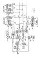
- the circuitry of Fig. 4 is controlled by a master oscillator 20.
- the master frequency is divided by a line divider 22 to drive a line blanking generator 24 and a line sync generator 26 at line frequency.
- the line divider 22 also supplies a twice-line-frequency signal to a field divider 28 which in turn drives a field sync generator 30 and a field blanking generator 32 at field frequency.
- Line and field sync signals are mixed by sync mixer 34 and supplied via amplifier 36 to the v.d.u.
- Line and field blanking signals are mixed by blanking mixer 38 and supplied to an output circuit 40.
- Fig. 4 The remainder of Fig. 4 is concerned with the division of the areas A-G.
- the display can be defined in terms of transitions between the various segments, the transitions being illustrated in Fig. 5.
- the clock frequency of the master oscillator 20 is chosen such that it will divide by a whole number N to provide the desired line frequency.
- a given shift on the raster of one clock period for each sequential line will represent a displacement corresponding to the increment or decrement of a sloped line that is defined line sequentially.
- the line a corresponds to the transition between the side wall and ceiling of the simulated room.
- a signal representing the line a is derived in Fig. 3 by starting a counter 46 at the end of line blanking beginning the last line in field blanking and allowing it to divide (N+l) to the end of the field by means of slope index generator 48.
- the reset pulse derived in the (N+1) division is the line a in Fig. 5A.
- the clock pulse used in the (N+l) division for even fields is an inverted version of the clock pulse used in the odd fields.
- the sloped transition at floor level is obtained by a second counter 46 a and index generator 48 a operating on (N-l) and indexed to a start position at the beginning of line blanking at a selected position down the field.
- the resulting reset signal is the line b of Fig. 5B.
- the width b to c (Fig. 5C) is the number of clock pulses corresponding to the displayed width of the number of raster lines required for the skirting dimension.
- transition d - E lines are vertical and horizontal and are derived by counting line and field information in a vertical segment generator 42 and horizontal segment generator 44 respectively; having defined the transition lines a - p, these signals are processed by logic gates in the output circuit 40 to produce mutually exclusive segments.
- the output circuit 40 derives which segment the v.d.u. trace is in at any instant and gives corresponding enable signals A-G to the gating and switching unit 14, thus allowing the correct R,B,G signals for that instant to be switched to the v.d.u.
- the mixed blanking signals also permit the output circuit 40 to produce line and frame blanking by disabling the switching unit 14.
- the above method of generating the segments gives segments with smooth edges and clean transitions, and -avoids irregular or "corrugated" edges to the simulated parts.
- each colour composer may be assigned directly to a given segment.
- Fig. 6 illustrates a modification using digital techniques in colour generation.
- the circuitry in Fig. 6 may be used to replace that in the lower part of Fig. 2 for supplying the inputs A-G of the gating and switching unit 14.
- a single colour composer 10 is provided; this is identical with that described above.
- the modification of Fig. 6 constrains the apparatus to display prescribed colours only. Prescribed colours are stored as binary numbers in three memories 100, 102, 104 one each for red, green and blue.
- the number of bits (X) depends on the resolution required of the system and a suitable number is 8 which gives a resolution of one part in 2 8 for each R ,B,G component.
- the total possible combinations of R, B , G is 2 24 or over 16 x10 6 .
- Each of the R,B,G numbers selected are entered on a bus 106 which is connected to R,B,G latches such as 108 R,B,G and 110 R,B,G for each of the picture segments and the required analog outputs obtained by digital to analog convertors 111.
- the purpose of the latches 108 etc. is to hold the binary numbers while the buses 106 are supplied with a different set of numbers for another segment.
- Memory size is related to the number of colours to be made available; hence, if a memory of 512 x 8 is used the 512 colours are made available by applying the suitable 9 bit address (Y) to the memories.
- Mode 1 - Keyboard entry If 9 bits are used then up to 512 keys can be installed in a keyboard 114. Operating any key for a particular colour generates the appropriate 9 bit address in a keyboard encoder 116 which is passed to a data selector 118. With the switch 112 in Mode 1 this address is passed to the memories 100, 102, 104 via the data selector 118. The colour selected will be displayed in whichever segment is.chosen by a segment select switch 120. Moving the segment select switch 120 to another segment will cause the previous segment latches 108 etc. to hold the binary numbers currently on the buses l06 even if the buses l06 are then re-numbered. Thus all the segments can be coloured in sequence.
- Mode 2 - External This provides for colour schemes to be entered into the equipment from an external source which may be schemes recorded on an audio tape recorder.
- the data will be entered in serial form in a segment sequence with appropriate latch control information which would be coded at the end of the colour data.
- An interface circuit 122 raises the incoming data stream to * logic levels, separates the memory address data and latch control data, and passes the latch control data to the latch control and the colour address to a serial to parallel converter 124.
- the data selector 118 passes the colour address to the memories 100, 102, 104 and the buses 106 are loaded with the colour information for the appropriate segment.
- the latches of the appropriate segment are enabled and the colour stored. This process is repeated for the next segment until the whole colour scheme is complete.
- an end of sequence pulse code from the recorder could be used to switch off the recorder until a decision is made to allow entry of the next colour scheme and the recorder control overriden.
- Mode 3 - Colour Composer In this mode a colour composer is used as if it had the complete flexibility to compose any colour but is constrained to produce only the prescribed colours.
- the colour composer 10 is as described above.
- the R,B,G outputs from the colour composer 10 are converted to binary numbers in three analog to digital converters 126 and the numbers passed to a digital comparator 128. These numbers are compared with the numbers on the R,B,G buses l06 and if parity is achieved either exactly or within prescribed limits (e.g. + 1 bit) then a parity pulse is generated on line 130. Its use will be described later.
- a Y bit counter 132 (in this case 9 bits) is clocked at reasonably.high rate, say 1 MHz, and all bits are applied to the data selector 118 which in this mode passes them to the memory addresses. Thus all addresses are scanned in approximately .5 msec. If the required parity is obtained in the scan then the parity pulse stops the counter 132 and enables the selected segment latch 108 etc. to display the colour corresponding to this address. If the colour composer controls are then moved to a different setting the parity pulse goes to zero thus causing the colour to latch at the selected segment and then after a built-in delay the counter 132 is enabled and continues to count until parity is again reached.
- the segment pattern could be chosen to be a simulation of another artefact (e.g. a vehicle, an article of furniture, or an article of dress) to allow the relationship of areas of different colour on the artefact to be judged.
- I Circuitry may be included to superimpose a black pattern on a given area, e.g. to simulate the texture of a carpet or folds in a curtain.
- the curtain G of Fig. 1 can be given the appearance of draped folds by modulating the video input during this segment with additional black in the form of a slow sine wave.
- each R,B,G component is modulated in proportion to its level so as to avoid changes of hue during the shading variations.
- the,eye scales the brightness of a source relative to the brightness of the scene as a whole.
- a dark colour as dark except with reference to a light one.
- a brightness reference would be required. This may be a white frame around the picture on the v.d.u., which can easily be derived by gating white-level signals to the appropriate part of the display.
- an external light source may be positioned immediately beside the v.d.u. screen, e.g. a fluorescent tube above the screen and adjusted in brightness to be equal to peak picture white.
- the source should also have a colour temperature compatible the colour temperature under which a realisation of the simulated object would be viewed in practice, e.g. a daylight fluorescent tube.
Landscapes
- Engineering & Computer Science (AREA)
- Physics & Mathematics (AREA)
- Computer Hardware Design (AREA)
- General Physics & Mathematics (AREA)
- Theoretical Computer Science (AREA)
- Multimedia (AREA)
- Signal Processing (AREA)
- Processing Of Color Television Signals (AREA)
Applications Claiming Priority (2)
| Application Number | Priority Date | Filing Date | Title |
|---|---|---|---|
| GB7930627 | 1979-09-04 | ||
| GB7930627 | 1979-09-04 |
Publications (2)
| Publication Number | Publication Date |
|---|---|
| EP0024862A2 true EP0024862A2 (de) | 1981-03-11 |
| EP0024862A3 EP0024862A3 (de) | 1981-03-25 |
Family
ID=10507604
Family Applications (1)
| Application Number | Title | Priority Date | Filing Date |
|---|---|---|---|
| EP80302832A Withdrawn EP0024862A3 (de) | 1979-09-04 | 1980-08-18 | Videogerät, mit dem ausgewählte Farben nebeneinander dargestellt werden können |
Country Status (5)
| Country | Link |
|---|---|
| US (1) | US4329710A (de) |
| EP (1) | EP0024862A3 (de) |
| AU (1) | AU530660B2 (de) |
| BR (1) | BR8005612A (de) |
| ZA (1) | ZA805205B (de) |
Cited By (3)
| Publication number | Priority date | Publication date | Assignee | Title |
|---|---|---|---|---|
| US4539585A (en) * | 1981-07-10 | 1985-09-03 | Spackova Daniela S | Previewer |
| EP0106601A3 (en) * | 1982-09-29 | 1986-02-26 | Fanuc Ltd | Color display unit |
| US5026617A (en) * | 1989-02-13 | 1991-06-25 | Idemitsu Kosan Company Limited | Separator for alkaline cell and alkaline cell prepared by using this separator |
Families Citing this family (35)
| Publication number | Priority date | Publication date | Assignee | Title |
|---|---|---|---|---|
| DE3037779A1 (de) * | 1980-10-07 | 1982-05-13 | Robert Bosch Gmbh, 7000 Stuttgart | System zum mischen zweier farbfernsehsignale |
| US5216755A (en) * | 1980-12-04 | 1993-06-01 | Quantel Limited | Video image creation system which proportionally mixes previously created image pixel data with currently created data |
| US5289566A (en) * | 1980-12-04 | 1994-02-22 | Quantel, Ltd. | Video image creation |
| GB2116407B (en) * | 1982-03-11 | 1986-04-23 | Quantel Ltd | Electonically synthesised video palette |
| US4473838A (en) * | 1982-10-15 | 1984-09-25 | Central Dynamics Ltd. | Digital color generator |
| US4580134A (en) * | 1982-11-16 | 1986-04-01 | Real Time Design, Inc. | Color video system using data compression and decompression |
| US5459529A (en) * | 1983-01-10 | 1995-10-17 | Quantel, Ltd. | Video processing for composite images |
| FR2546021B1 (fr) * | 1983-05-10 | 1986-01-17 | Thomson Csf | Procede et dispositif de reglage d'un fond colore dans une image de television |
| GB2155286B (en) * | 1984-02-27 | 1987-04-23 | Philips Electronic Associated | Character memory addressing for data display |
| US4583186A (en) * | 1984-03-26 | 1986-04-15 | Bremson Data Systems | Computerized video imaging system |
| USRE33244E (en) * | 1984-03-26 | 1990-06-26 | Bremson Data Systems | Computerized video imaging system |
| US4709230A (en) * | 1985-04-19 | 1987-11-24 | Questron, Inc. | Color converter |
| US5053956A (en) * | 1985-06-17 | 1991-10-01 | Coats Viyella | Interactive system for retail transactions |
| US5093717A (en) * | 1987-08-03 | 1992-03-03 | American Film Technologies, Inc. | System and method for digitally coloring images |
| US4984072A (en) * | 1987-08-03 | 1991-01-08 | American Film Technologies, Inc. | System and method for color image enhancement |
| US5726898A (en) * | 1994-09-01 | 1998-03-10 | American Greetings Corporation | Method and apparatus for storing and selectively retrieving and delivering product data based on embedded expert judgements |
| US5550746A (en) * | 1994-12-05 | 1996-08-27 | American Greetings Corporation | Method and apparatus for storing and selectively retrieving product data by correlating customer selection criteria with optimum product designs based on embedded expert judgments |
| US5768142A (en) * | 1995-05-31 | 1998-06-16 | American Greetings Corporation | Method and apparatus for storing and selectively retrieving product data based on embedded expert suitability ratings |
| US5875110A (en) * | 1995-06-07 | 1999-02-23 | American Greetings Corporation | Method and system for vending products |
| US8897596B1 (en) | 2001-05-04 | 2014-11-25 | Legend3D, Inc. | System and method for rapid image sequence depth enhancement with translucent elements |
| US9286941B2 (en) | 2001-05-04 | 2016-03-15 | Legend3D, Inc. | Image sequence enhancement and motion picture project management system |
| US8401336B2 (en) | 2001-05-04 | 2013-03-19 | Legend3D, Inc. | System and method for rapid image sequence depth enhancement with augmented computer-generated elements |
| US8467090B2 (en) * | 2009-03-03 | 2013-06-18 | Columbia Insurance Company | Color selection apparatus and method for producing low metameric color merchandise |
| EP2384904B1 (de) * | 2010-05-04 | 2013-04-24 | Benjamin Moore&Co. | Vorrichtung und Verfahren zur Verteilung von Farbmustern |
| US8730232B2 (en) | 2011-02-01 | 2014-05-20 | Legend3D, Inc. | Director-style based 2D to 3D movie conversion system and method |
| US9407904B2 (en) | 2013-05-01 | 2016-08-02 | Legend3D, Inc. | Method for creating 3D virtual reality from 2D images |
| US9288476B2 (en) | 2011-02-17 | 2016-03-15 | Legend3D, Inc. | System and method for real-time depth modification of stereo images of a virtual reality environment |
| US9241147B2 (en) | 2013-05-01 | 2016-01-19 | Legend3D, Inc. | External depth map transformation method for conversion of two-dimensional images to stereoscopic images |
| US9282321B2 (en) | 2011-02-17 | 2016-03-08 | Legend3D, Inc. | 3D model multi-reviewer system |
| US9007365B2 (en) | 2012-11-27 | 2015-04-14 | Legend3D, Inc. | Line depth augmentation system and method for conversion of 2D images to 3D images |
| US9547937B2 (en) | 2012-11-30 | 2017-01-17 | Legend3D, Inc. | Three-dimensional annotation system and method |
| US9007404B2 (en) | 2013-03-15 | 2015-04-14 | Legend3D, Inc. | Tilt-based look around effect image enhancement method |
| US9438878B2 (en) | 2013-05-01 | 2016-09-06 | Legend3D, Inc. | Method of converting 2D video to 3D video using 3D object models |
| US9609307B1 (en) | 2015-09-17 | 2017-03-28 | Legend3D, Inc. | Method of converting 2D video to 3D video using machine learning |
| JP2017219586A (ja) * | 2016-06-03 | 2017-12-14 | 株式会社ジャパンディスプレイ | 信号供給回路及び表示装置 |
Family Cites Families (5)
| Publication number | Priority date | Publication date | Assignee | Title |
|---|---|---|---|---|
| DE2256674A1 (de) * | 1971-11-18 | 1973-05-24 | Midland Ind Computing | Vorrichtung zur erzeugung von farbigen darstellungen |
| US3978470A (en) * | 1974-07-10 | 1976-08-31 | Midwest Analog And Digital, Inc. | Multi-channel data color display apparatus |
| US4119956A (en) * | 1975-06-30 | 1978-10-10 | Redifon Flight Simulation Limited | Raster-scan display apparatus for computer-generated images |
| US4007327A (en) * | 1975-07-30 | 1977-02-08 | Compagnie Industrielle Des Telecommunications Cit-Alcatel | Apparatus for selectively altering image data for CRT display in order to facilitate image analysis |
| US4229760A (en) * | 1978-05-26 | 1980-10-21 | Rca Corporation | Video games color synthesis |
-
1980
- 1980-08-18 EP EP80302832A patent/EP0024862A3/de not_active Withdrawn
- 1980-08-20 US US06/179,871 patent/US4329710A/en not_active Expired - Lifetime
- 1980-08-22 ZA ZA00805205A patent/ZA805205B/xx unknown
- 1980-08-27 AU AU61789/80A patent/AU530660B2/en not_active Ceased
- 1980-09-03 BR BR8005612A patent/BR8005612A/pt unknown
Cited By (3)
| Publication number | Priority date | Publication date | Assignee | Title |
|---|---|---|---|---|
| US4539585A (en) * | 1981-07-10 | 1985-09-03 | Spackova Daniela S | Previewer |
| EP0106601A3 (en) * | 1982-09-29 | 1986-02-26 | Fanuc Ltd | Color display unit |
| US5026617A (en) * | 1989-02-13 | 1991-06-25 | Idemitsu Kosan Company Limited | Separator for alkaline cell and alkaline cell prepared by using this separator |
Also Published As
| Publication number | Publication date |
|---|---|
| AU530660B2 (en) | 1983-07-21 |
| ZA805205B (en) | 1981-08-26 |
| BR8005612A (pt) | 1981-03-17 |
| EP0024862A3 (de) | 1981-03-25 |
| US4329710A (en) | 1982-05-11 |
| AU6178980A (en) | 1981-03-19 |
Similar Documents
| Publication | Publication Date | Title |
|---|---|---|
| US4329710A (en) | Color composing video system | |
| US4021841A (en) | Color video synthesizer with improved image control means | |
| JPS6022864B2 (ja) | 像結合装置 | |
| CA1215186A (en) | Liquid crystal image display | |
| US4038668A (en) | Apparatus for producing smooth and continuous graphic displays from intermittently sampled data | |
| Davis | Automation of a production switching system | |
| US4093960A (en) | Test signal generating system and method | |
| US4284988A (en) | Control means to provide slow scrolling positioning and spacing in a digital video display system | |
| US5119186A (en) | Color mapping system and method | |
| NL7908906A (nl) | Werkwijze voor kleurbeoordeling van patroonoriginelen voor het bedrukken van textiel, decoratie- en verpakkingsmaterialen en kleurbeoordelingsinrichting. | |
| US20070115360A1 (en) | Video generator with NTSC/PAL conversion capability | |
| US4158200A (en) | Digital video display system with a plurality of gray-scale levels | |
| US3961365A (en) | Color display device | |
| WO1999062267A9 (en) | Automatic test instrument for multi-format video generation and capture | |
| US4577188A (en) | Level display device for audio signal | |
| DE69330692T2 (de) | Vorrichtung zur Überblendung von Videosignalen | |
| CN1090865C (zh) | 在屏幕上显示色调调节状态的彩色图像设备 | |
| US4413273A (en) | System for mixing two color television signals | |
| US3784874A (en) | Lighting control systems | |
| EP0461368A2 (de) | Video-Schnittstellen-Schaltung | |
| EP0268360A2 (de) | System zur Verarbeitung von Fernsehbildsignalen | |
| JPH0258635B2 (de) | ||
| US4536707A (en) | Method and apparatus for displaying one or more measurement values of arbitrary measurement variables on a screen | |
| JPS62249569A (ja) | テレビジヨン作図装置 | |
| JPH033028Y2 (de) |
Legal Events
| Date | Code | Title | Description |
|---|---|---|---|
| PUAI | Public reference made under article 153(3) epc to a published international application that has entered the european phase |
Free format text: ORIGINAL CODE: 0009012 |
|
| PUAL | Search report despatched |
Free format text: ORIGINAL CODE: 0009013 |
|
| AK | Designated contracting states |
Designated state(s): AT BE CH DE FR GB IT NL SE |
|
| AK | Designated contracting states |
Designated state(s): AT BE CH DE FR GB IT NL SE |
|
| 17P | Request for examination filed |
Effective date: 19810904 |
|
| STAA | Information on the status of an ep patent application or granted ep patent |
Free format text: STATUS: THE APPLICATION IS DEEMED TO BE WITHDRAWN |
|
| 18D | Application deemed to be withdrawn |
Effective date: 19850301 |