EP0024913B1 - Electrodes pour stimulateurs cardiaques - Google Patents
Electrodes pour stimulateurs cardiaques Download PDFInfo
- Publication number
- EP0024913B1 EP0024913B1 EP80302946A EP80302946A EP0024913B1 EP 0024913 B1 EP0024913 B1 EP 0024913B1 EP 80302946 A EP80302946 A EP 80302946A EP 80302946 A EP80302946 A EP 80302946A EP 0024913 B1 EP0024913 B1 EP 0024913B1
- Authority
- EP
- European Patent Office
- Prior art keywords
- electrode
- atrial
- catheter
- ventricular
- dual
- Prior art date
- Legal status (The legal status is an assumption and is not a legal conclusion. Google has not performed a legal analysis and makes no representation as to the accuracy of the status listed.)
- Expired
Links
Images
Classifications
-
- A—HUMAN NECESSITIES
- A61—MEDICAL OR VETERINARY SCIENCE; HYGIENE
- A61N—ELECTROTHERAPY; MAGNETOTHERAPY; RADIATION THERAPY; ULTRASOUND THERAPY
- A61N1/00—Electrotherapy; Circuits therefor
- A61N1/02—Details
- A61N1/04—Electrodes
- A61N1/05—Electrodes for implantation or insertion into the body, e.g. heart electrode
- A61N1/056—Transvascular endocardial electrode systems
Definitions
- This invention relates to electrodes for cardiac pacemakers, and particularly to transvenous electrodes suitable for atrial sensing and ventricular pacing, for A-V sequential pacing or bifocal pacing.
- Typical examples of dual electrodes for A-V pacing are described in De-Al-2 605 590 and US-A-3 865 118.
- I provide a dual electrode for use in cardiac pacemaking to enable both ventricular and atrial electrical contact to be made, said electrode comprising:
- the atrial electrodes are preferably formed as prongs extending outwardly from the catheter. At least two, and preferably three such prongs are employed.
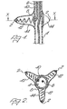
- the dual electrode illustrated has a ventricular stimulating tip electrode at its distal end (not shown) and three atrial electrodes 2.
- the ventricular tip electrode employed may be any of those currently in use, for example a screw-in or contact type, with a surface shape and area as desired.
- the atrial electrodes 2 are disposed approximately 13 to 17 cms back from the tip and are radially-disposed about a central catheter 4 of electrically-insulating flexible plastics tubing.
- An insulated electrical conductor 6 which makes connection with the ventricular tip electrode passes along catheter 4 to the proximal terminal of the electrode, as is conventional.
- An electrically-conductive metal ring 8 makes contact with and circumscribes catheter 4. Electrically connected to ring 8 and passing through the catheter wall is a second insulated electrical conductor 10. Also connected to ring 8 and extending radially outwardly therefrom are three electrically-conductive metal springs 12. The springs are respectively connected to an atrial electrode 2 and enable electrical connection between the atrial electrodes 2 and conductor 10 to be made. The conductor 10 passes along cathether 4 to the proximal terminal of the electrode.
- the atrial electrodes 2 are maintained in a sheath of thin electrically-insulating flexible plastics material 14.
- the electrodes thus form three radially-disposed prongs biassed outwardly under the influence of springs 12.
- the radial length of each prong is typically from 0.5 to 1.5 cms.
- the sheath 14 is sealed to catheter 4 just beyond each side of the prongs.
- the prongs are flexible and therefore allow the entire electrode to be introduced through a vein of suitable size such as the jugular sub- clavian or cephalic.
- the stimulating distal tip of the electrode can be positioned in the ideal position within the right ventricle and the prongs will then make contact with the lateral wall of the right atrium even although the course of the electrical conductors 6 and 10 lies within the cavity of the right atrium, away from the wall.
- the prongs are of such flexibility as to make adequate contact with the right atrial wall at one or more points and the tips are conductive with small area electrodes.
- the stiffness of the prongs can be influenced by the sheath material chosen (such as silicone rubber), by the dimensions and shape of the prongs, or by the incorporation of central stiffness such as the springs illustrated or flexible rod of metal.
- the contact tips of the prongs can be shaped with a small radius of curvature to provide a high current density and pacing will occur through whichever of the prongs is contacting the atrial wall.
- the prongs can alternatively be made conducting-themselves, for example, by "filling" the insulating material 14 with biocompatible conducting elements such as carbon, or by surface coating with a flexible conducting layer of biocompatible material, such as gold.
- the sheath 14 might only be sealed to the catheter 4 on the distal side of the prongs. On the proximal side the sheath 14 could then extend to the proximal end of the electrode with the conductor 10 extending to the proximal end in the annular gap between catheter 4 and sheath 14. In this manner, catheter 4 need not be pierced to allow passage of conductor 10 therethrough and, indeed, the insulation of one or both of conductors 6 and 10 could be omitted if desired.
- the invention is not restricted to the use of three atrial electrodes and more, or less prongs could be employed if wished, although 3, in the configuration illustrated, is thought to be the optimum.
- a single continuous atrial electrode, spaced apart from and circumscribing catheter 4 may be employed.
- the atrial electrode would be similar to a small floppy disc extending outwardly from catheter 4.
- a coaxial cable with twin coaxial conductors may be employed.
Landscapes
- Health & Medical Sciences (AREA)
- Heart & Thoracic Surgery (AREA)
- Vascular Medicine (AREA)
- Cardiology (AREA)
- Engineering & Computer Science (AREA)
- Biomedical Technology (AREA)
- Nuclear Medicine, Radiotherapy & Molecular Imaging (AREA)
- Radiology & Medical Imaging (AREA)
- Life Sciences & Earth Sciences (AREA)
- Animal Behavior & Ethology (AREA)
- General Health & Medical Sciences (AREA)
- Public Health (AREA)
- Veterinary Medicine (AREA)
- Electrotherapy Devices (AREA)
Claims (9)
Priority Applications (1)
| Application Number | Priority Date | Filing Date | Title |
|---|---|---|---|
| AT80302946T ATE4861T1 (de) | 1979-08-28 | 1980-08-26 | Herzschrittmacher-elektroden. |
Applications Claiming Priority (2)
| Application Number | Priority Date | Filing Date | Title |
|---|---|---|---|
| GB7929735 | 1979-08-28 | ||
| GB7929735 | 1979-08-28 |
Publications (2)
| Publication Number | Publication Date |
|---|---|
| EP0024913A1 EP0024913A1 (fr) | 1981-03-11 |
| EP0024913B1 true EP0024913B1 (fr) | 1983-10-05 |
Family
ID=10507448
Family Applications (1)
| Application Number | Title | Priority Date | Filing Date |
|---|---|---|---|
| EP80302946A Expired EP0024913B1 (fr) | 1979-08-28 | 1980-08-26 | Electrodes pour stimulateurs cardiaques |
Country Status (4)
| Country | Link |
|---|---|
| US (1) | US4386615A (fr) |
| EP (1) | EP0024913B1 (fr) |
| AT (1) | ATE4861T1 (fr) |
| DE (1) | DE3065166D1 (fr) |
Families Citing this family (21)
| Publication number | Priority date | Publication date | Assignee | Title |
|---|---|---|---|---|
| US4497326A (en) * | 1981-04-06 | 1985-02-05 | Curry Paul V L | Heart pacing lead |
| WO1988010092A1 (fr) * | 1987-06-25 | 1988-12-29 | Terumo Kabushiki Kaisha | Catheter pourvu d'un fil conducteur incorpore |
| US5423878A (en) * | 1984-03-06 | 1995-06-13 | Ep Technologies, Inc. | Catheter and associated system for pacing the heart |
| EP0159753A1 (fr) * | 1984-04-16 | 1985-10-30 | Eliezer A. Astrinski | Conducteur cardiaque |
| US4608986A (en) * | 1984-10-01 | 1986-09-02 | Cordis Corporation | Pacing lead with straight wire conductors |
| US6738673B2 (en) | 1986-11-14 | 2004-05-18 | Jawahar M. Desai | Method for catheter mapping and ablation |
| US5215103A (en) * | 1986-11-14 | 1993-06-01 | Desai Jawahar M | Catheter for mapping and ablation and method therefor |
| US5365926A (en) * | 1986-11-14 | 1994-11-22 | Desai Jawahar M | Catheter for mapping and ablation and method therefor |
| US5231995A (en) * | 1986-11-14 | 1993-08-03 | Desai Jawahar M | Method for catheter mapping and ablation |
| WO1992004074A1 (fr) * | 1990-09-10 | 1992-03-19 | Ep Technologies Inc. | Dispositif et procede de stimulation cardiaque in vivo |
| US5190052A (en) * | 1990-11-21 | 1993-03-02 | Intermedics, Inc. | Pacer lead with bipolar electrode |
| US5433729A (en) * | 1991-04-12 | 1995-07-18 | Incontrol, Inc. | Atrial defibrillator, lead systems, and method |
| US5674274A (en) * | 1995-12-14 | 1997-10-07 | Pacesetter, Inc. | Implantable adjustable single-pass A-V lead for use with an implantable stimulation device |
| US5922014A (en) * | 1997-09-02 | 1999-07-13 | Medtronic, Inc. | Single pass lead and method of use |
| US5991668A (en) * | 1997-09-25 | 1999-11-23 | Medtronic, Inc. | Medical electrical lead |
| US6148238A (en) * | 1998-08-10 | 2000-11-14 | Medtronic, Inc. | Pacing leads having a brachiocephalic tine or star tine |
| US8442657B2 (en) * | 2007-10-16 | 2013-05-14 | Cardiac Pacemakers, Inc. | Stimulation and sensing lead with non-coiled wire construction |
| US8112160B2 (en) | 2007-12-14 | 2012-02-07 | Cardiac Pacemakers, Inc. | Fixation helix and multipolar medical electrode |
| US9480834B2 (en) | 2012-05-08 | 2016-11-01 | Cardiac Pacemakers, Inc. | Multipolar conductor for an implantable medical device |
| US9072864B2 (en) | 2012-11-28 | 2015-07-07 | Ad-Tech Medical Instrument Corporation | Catheter with depth electrode for dual-purpose use |
| US9750422B2 (en) * | 2014-02-12 | 2017-09-05 | Biosense Webster (Israel) Ltd | Catheter with transverse branches |
Family Cites Families (8)
| Publication number | Priority date | Publication date | Assignee | Title |
|---|---|---|---|---|
| US3348548A (en) * | 1965-04-26 | 1967-10-24 | William M Chardack | Implantable electrode with stiffening stylet |
| US3729008A (en) * | 1970-12-28 | 1973-04-24 | American Optical Corp | Electrode for atrial pacing with curved end for atrial wall engagement |
| US3893461A (en) * | 1972-11-28 | 1975-07-08 | Thomas A Preston | Pacing apparatus and method utilizing improved catheter |
| DE2334049C3 (de) * | 1973-07-04 | 1988-12-22 | Lagergren, Hans, Dr.Med., Stockholm | Endocard-elektrodenanordnung |
| US3865118A (en) * | 1973-12-27 | 1975-02-11 | Univ California | Transvenous coaxial catheter |
| US3949757A (en) * | 1974-05-13 | 1976-04-13 | Sabel George H | Catheter for atrio-ventricular pacemaker |
| US3981309A (en) * | 1974-12-23 | 1976-09-21 | American Optical Corporation | Patient stimulating pacer electrode |
| DE2605590A1 (de) * | 1976-02-12 | 1977-08-18 | Heinz Dr Med Praeuer | Herzschrittmacherelektrode |
-
1980
- 1980-08-04 US US06/175,346 patent/US4386615A/en not_active Expired - Lifetime
- 1980-08-26 EP EP80302946A patent/EP0024913B1/fr not_active Expired
- 1980-08-26 AT AT80302946T patent/ATE4861T1/de not_active IP Right Cessation
- 1980-08-26 DE DE8080302946T patent/DE3065166D1/de not_active Expired
Also Published As
| Publication number | Publication date |
|---|---|
| US4386615A (en) | 1983-06-07 |
| DE3065166D1 (en) | 1983-11-10 |
| ATE4861T1 (de) | 1983-10-15 |
| EP0024913A1 (fr) | 1981-03-11 |
Similar Documents
| Publication | Publication Date | Title |
|---|---|---|
| EP0024913B1 (fr) | Electrodes pour stimulateurs cardiaques | |
| EP0428279B1 (fr) | Conducteurs d'électrode tressés et cathéters pour leur utilisation | |
| US7027852B2 (en) | Lead with distal tip surface electrodes connected in parallel | |
| US4030508A (en) | Low output electrode for cardiac pacing | |
| US5578068A (en) | Medical electrical lead with radially asymmetric tip | |
| US5545201A (en) | Bipolar active fixation lead for sensing and pacing the heart | |
| US7412289B2 (en) | Multi-electrode lead | |
| US5330520A (en) | Implantable electrode and sensor lead apparatus | |
| US6671562B2 (en) | High impedance drug eluting cardiac lead | |
| US4458695A (en) | Multipolar electrode assembly for pacing lead | |
| CA1150775A (fr) | Fils d'electrode munis de fourchons | |
| EP0191238B1 (fr) | Conducteur pour stimulateur cardiaque à sensibilité élevée | |
| US4469104A (en) | Multipolar connector for pacing lead | |
| US7212870B1 (en) | Dual helix active fixation stimulation lead | |
| US5342414A (en) | Transvenous defibrillation lead | |
| US5044375A (en) | Unitary intravascular defibrillating catheter with separate bipolar sensing | |
| US7139614B2 (en) | Leads for pacing and/or sensing the heart from within the coronary veins | |
| US4393883A (en) | Single pass A-V lead | |
| JPH0216768Y2 (fr) | ||
| US6505082B1 (en) | Single pass lead system | |
| US20030060868A1 (en) | High impedance electrode tip | |
| JPH08506263A (ja) | センシング能を有するペーシングおよび除細動用リード | |
| WO2003041791A2 (fr) | Conducteur multifilaire pour conducteurs endocardiques | |
| JP2008521581A (ja) | 電気的医療リードの高インピーダンスのアクティブな固定電極 | |
| GB1537101A (en) | Electromedical leads |
Legal Events
| Date | Code | Title | Description |
|---|---|---|---|
| PUAI | Public reference made under article 153(3) epc to a published international application that has entered the european phase |
Free format text: ORIGINAL CODE: 0009012 |
|
| AK | Designated contracting states |
Designated state(s): AT BE CH DE FR GB IT LI NL SE |
|
| 17P | Request for examination filed |
Effective date: 19810821 |
|
| ITF | It: translation for a ep patent filed | ||
| GRAA | (expected) grant |
Free format text: ORIGINAL CODE: 0009210 |
|
| RAP1 | Party data changed (applicant data changed or rights of an application transferred) |
Owner name: AMERICAN PACEMAKER CORPORATION |
|
| AK | Designated contracting states |
Designated state(s): AT BE CH DE FR GB IT LI NL SE |
|
| REF | Corresponds to: |
Ref document number: 4861 Country of ref document: AT Date of ref document: 19831015 Kind code of ref document: T |
|
| ET | Fr: translation filed | ||
| REF | Corresponds to: |
Ref document number: 3065166 Country of ref document: DE Date of ref document: 19831110 |
|
| PLBE | No opposition filed within time limit |
Free format text: ORIGINAL CODE: 0009261 |
|
| STAA | Information on the status of an ep patent application or granted ep patent |
Free format text: STATUS: NO OPPOSITION FILED WITHIN TIME LIMIT |
|
| PGFP | Annual fee paid to national office [announced via postgrant information from national office to epo] |
Ref country code: FR Payment date: 19840824 Year of fee payment: 5 Ref country code: DE Payment date: 19840824 Year of fee payment: 5 |
|
| PGFP | Annual fee paid to national office [announced via postgrant information from national office to epo] |
Ref country code: CH Payment date: 19840910 Year of fee payment: 5 |
|
| PGFP | Annual fee paid to national office [announced via postgrant information from national office to epo] |
Ref country code: SE Payment date: 19840930 Year of fee payment: 5 Ref country code: BE Payment date: 19840930 Year of fee payment: 5 |
|
| 26N | No opposition filed | ||
| PGFP | Annual fee paid to national office [announced via postgrant information from national office to epo] |
Ref country code: AT Payment date: 19850819 Year of fee payment: 6 |
|
| PGFP | Annual fee paid to national office [announced via postgrant information from national office to epo] |
Ref country code: NL Payment date: 19850831 Year of fee payment: 6 |
|
| PG25 | Lapsed in a contracting state [announced via postgrant information from national office to epo] |
Ref country code: AT Effective date: 19860826 |
|
| PG25 | Lapsed in a contracting state [announced via postgrant information from national office to epo] |
Ref country code: SE Effective date: 19860827 |
|
| PG25 | Lapsed in a contracting state [announced via postgrant information from national office to epo] |
Ref country code: LI Effective date: 19860831 Ref country code: CH Effective date: 19860831 |
|
| BERE | Be: lapsed |
Owner name: AMERICAN PACEMAKER CORP. Effective date: 19860831 |
|
| PG25 | Lapsed in a contracting state [announced via postgrant information from national office to epo] |
Ref country code: NL Effective date: 19870301 |
|
| NLV4 | Nl: lapsed or anulled due to non-payment of the annual fee | ||
| GBPC | Gb: european patent ceased through non-payment of renewal fee | ||
| PG25 | Lapsed in a contracting state [announced via postgrant information from national office to epo] |
Ref country code: FR Free format text: LAPSE BECAUSE OF NON-PAYMENT OF DUE FEES Effective date: 19870430 |
|
| REG | Reference to a national code |
Ref country code: CH Ref legal event code: PL |
|
| PG25 | Lapsed in a contracting state [announced via postgrant information from national office to epo] |
Ref country code: DE Effective date: 19870501 |
|
| REG | Reference to a national code |
Ref country code: FR Ref legal event code: ST |
|
| PG25 | Lapsed in a contracting state [announced via postgrant information from national office to epo] |
Ref country code: GB Effective date: 19881118 |
|
| PG25 | Lapsed in a contracting state [announced via postgrant information from national office to epo] |
Ref country code: BE Effective date: 19890831 |
|
| EUG | Se: european patent has lapsed |
Ref document number: 80302946.1 Effective date: 19870812 |