EP0024969A1 - Messmaschine und Verfahren zur Erzeugung von Verschiebungsanzeigesignalen in einer solchen Maschine - Google Patents
Messmaschine und Verfahren zur Erzeugung von Verschiebungsanzeigesignalen in einer solchen Maschine Download PDFInfo
- Publication number
- EP0024969A1 EP0024969A1 EP80401146A EP80401146A EP0024969A1 EP 0024969 A1 EP0024969 A1 EP 0024969A1 EP 80401146 A EP80401146 A EP 80401146A EP 80401146 A EP80401146 A EP 80401146A EP 0024969 A1 EP0024969 A1 EP 0024969A1
- Authority
- EP
- European Patent Office
- Prior art keywords
- photodetectors
- indicative
- address
- measuring machine
- measurement
- Prior art date
- Legal status (The legal status is an assumption and is not a legal conclusion. Google has not performed a legal analysis and makes no representation as to the accuracy of the status listed.)
- Withdrawn
Links
Images



Classifications
-
- G—PHYSICS
- G01—MEASURING; TESTING
- G01D—MEASURING NOT SPECIALLY ADAPTED FOR A SPECIFIC VARIABLE; ARRANGEMENTS FOR MEASURING TWO OR MORE VARIABLES NOT COVERED IN A SINGLE OTHER SUBCLASS; TARIFF METERING APPARATUS; MEASURING OR TESTING NOT OTHERWISE PROVIDED FOR
- G01D5/00—Mechanical means for transferring the output of a sensing member; Means for converting the output of a sensing member to another variable where the form or nature of the sensing member does not constrain the means for converting; Transducers not specially adapted for a specific variable
- G01D5/26—Mechanical means for transferring the output of a sensing member; Means for converting the output of a sensing member to another variable where the form or nature of the sensing member does not constrain the means for converting; Transducers not specially adapted for a specific variable characterised by optical transfer means, i.e. using infrared, visible, or ultraviolet light
- G01D5/32—Mechanical means for transferring the output of a sensing member; Means for converting the output of a sensing member to another variable where the form or nature of the sensing member does not constrain the means for converting; Transducers not specially adapted for a specific variable characterised by optical transfer means, i.e. using infrared, visible, or ultraviolet light with attenuation or whole or partial obturation of beams of light
- G01D5/34—Mechanical means for transferring the output of a sensing member; Means for converting the output of a sensing member to another variable where the form or nature of the sensing member does not constrain the means for converting; Transducers not specially adapted for a specific variable characterised by optical transfer means, i.e. using infrared, visible, or ultraviolet light with attenuation or whole or partial obturation of beams of light the beams of light being detected by photocells
- G01D5/36—Forming the light into pulses
-
- G—PHYSICS
- G01—MEASURING; TESTING
- G01D—MEASURING NOT SPECIALLY ADAPTED FOR A SPECIFIC VARIABLE; ARRANGEMENTS FOR MEASURING TWO OR MORE VARIABLES NOT COVERED IN A SINGLE OTHER SUBCLASS; TARIFF METERING APPARATUS; MEASURING OR TESTING NOT OTHERWISE PROVIDED FOR
- G01D5/00—Mechanical means for transferring the output of a sensing member; Means for converting the output of a sensing member to another variable where the form or nature of the sensing member does not constrain the means for converting; Transducers not specially adapted for a specific variable
- G01D5/12—Mechanical means for transferring the output of a sensing member; Means for converting the output of a sensing member to another variable where the form or nature of the sensing member does not constrain the means for converting; Transducers not specially adapted for a specific variable using electric or magnetic means
- G01D5/244—Mechanical means for transferring the output of a sensing member; Means for converting the output of a sensing member to another variable where the form or nature of the sensing member does not constrain the means for converting; Transducers not specially adapted for a specific variable using electric or magnetic means influencing characteristics of pulses or pulse trains; generating pulses or pulse trains
- G01D5/24409—Interpolation using memories
-
- G—PHYSICS
- G01—MEASURING; TESTING
- G01P—MEASURING LINEAR OR ANGULAR SPEED, ACCELERATION, DECELERATION, OR SHOCK; INDICATING PRESENCE, ABSENCE, OR DIRECTION, OF MOVEMENT
- G01P13/00—Indicating or recording presence, absence, or direction, of movement
- G01P13/02—Indicating direction only, e.g. by weather vane
- G01P13/04—Indicating positive or negative direction of a linear movement or clockwise or anti-clockwise direction of a rotational movement
Definitions
- This invention relates to a method of producing displacement-indicative signals in a measuring machine and to such a machine of the type comprising: a base including a fixed grating; a movable member coupled to a movable grating positioned adjacent to the fixed grating; and at least first and second photodetectors, each positioned adjacent to the gratings for sensing relative movement of the gratings and each producing a signal indicative of a displacement of a predetermined magnitude of the movable grating.
- Measuring and layout machines typically have measuring systems which provide an indication of a displacement or measurement increment on a relatively gross scale (perhaps hundredths of a millimeter). These systems may create the measurement increment through the use of "Moire-fringe" gratings having five to fifty lines per millimeter in the case of a measuring machine.
- a rotary encoder is frequently provided having a pulse producing member in response to rotation.
- the present invention overcomes the limitations and disadvantages of the prior art systems by providing a measuring machine comprising: a base including a fixed grating; a movable member coupled to a movable grating positioned adjacent to the fixed grating; at least first and second photodetectors, each positioned adjacent to the gratings for sensing relative movement of the gratings and each producing a signal indicative of a displacement of a predetermined magnitude of the movable member; and means adapted to divide said predetermined magnitude into smaller regions and to produce signals for counting such regions, said means comprising: a memory including a stored value at each of a plurality of digital addresses; a logic coupled to the first and second photodetectors and to the memory for generating a binary word based upon present and past conditions of the first and second photodetectors; and means coupled to the memory for obtaining a signal based upon a stored value in the memory at an address corresponding to the binary word generated by the lo - gic, said signal being indicative of movement through a pre
- the present invention has the advantage that substantially all of the buffers and latches associated with prior circuits can be eliminated. Also, a substantial portion of the logic and interconnecting elements necessary in other designs can be eliminated.
- the present invention also has the advantage that conversion of input signals to output is provided by a reliable hard wire element such as a ROM (Read Only Memory) in which the representations of. the present and past states of the photodetectors have been stored to provide an indication of whether an up or down counter should be incremented respectively.
- a reliable hard wire element such as a ROM (Read Only Memory) in which the representations of. the present and past states of the photodetectors have been stored to provide an indication of whether an up or down counter should be incremented respectively.
- the machine according to the present invention is relatively simple to design, easy to troubleshoot and inexpensive to manufacture.
- FIGURE 1 is an enlarged schematic of a Moire fringe system 100 suitable for generating measurement pulses used in the present invention, especially in a coordinate measuring machine.
- This system 100 is also characteristic of other prior art systems to the extent disclosed in this Figure.
- the Moire fringe system 100 includes a first, long stationary grating 110, and a movable transducer 120,
- the transducer 120 carries a second movable grating 122 and a plurality of photodetectors 124,126.
- This transducer 120 also carries a lens and a light source (not shown) and is more specifically described in U.S. Patent 3,713,139.
- the first grating 110 includes a plurality of parallel lines 112'which are precisely positioned to be a fixed distance from the next line and parallel thereto. This grating is fixed to a frame of a measuring machine.
- the transducer 120 is mounted to a measuring probe to movably displace together'with the probe.
- the transducer 120 includes the grating 122 having parallel lines 123 on a transparent piece. These lines 123 are also equidistant one to the next.
- the photodetectors 124,126 are spaced laterally (perpendicular to the motion of the transducer) from each other by one quarter cycle of the periodic optical pattern to create a 90 degree offset of an observed sinusoidal (or converted square wave) pulse pattern between the photodetector outputs. Additional photodetectors could also be used, each spaced an additional one-quarter cycle offset from the adjacent photodetectors.
- the measurement source is frequently provided by a rotary encoder.
- the encoder includes a fixed rack and a movable pinion which rotates in response to linear displacement.
- the encoder provides square waves directly, and the two desired square waves may be chosen to be 90 degrees apart on the pinion rotation.
- FIGURE 2 is a block diagram representation of the present invention in connection with a measuring machine.
- the Moire fringe pattern is detected, as by the transducer 120 in FIGURE 1.
- the Moire fringe pattern is initially a sine wave.
- Offset sine waves created by the photodetectors are converted to square waves at block 220 through a conventional resistor network arrangement in a known manner. While the simple expedient of placing the photodetectors at a lateral offset distance of one quarter of the optical pattern will create a 90 degree offset in the waves created, other methods could be used to create waves having a different offset (i.e., a resistive network could be used with the offset photodetectors to create a plurality of square waves offset by any desired amount one to another). Such resistive networks are well known in the prior art and are not discussed in detail here for that reason.
- offset square waves After offset square waves have been generated, they are analyzed and a binary code is assigned to each of the possible states at block 230.
- the binary code from block 230(present and past) is used as an address in block 240 to look up values stored in a ROM (Read Only Memory) at that address.
- Output lines shown generally by reference numeral 250, transmit stored values from the ROM to indicate'whether the counter should be incremented or decremented. The output is from stored values in the ROM at the address from the binary code generated in the block 230.
- a ROM stored value (the output on lines 250) indicates, based upon the photodetectors present and past states, whether the measurement should be changed and, if so, in which direction.
- FIGURE 3 shows a pulse pattern from the apparatus of FIGURE 1 (after signal conditioning) and a digital code assigned to each combination of pulses.
- a digital code of 00 is produced.
- a digital code of 10 is assigned.
- a digital code of 11 is assigned.
- the photodetector 124 is low and the photodetector 126 is high, a digital code of 01 is assigned.
- the square wave outputs from photodetectors 124,126 are offset by a quarter of the optical pattern and each photodetector square wave has been adjusted to provide a high signal during one half of the cycle and a low signal during the other half of the cycle.
- Other positions and ratios between on time and off time could be used without departing significantly from the scope of the present invention.
- FIGURE 4 is a circuit diagram 400 of the present invention for a divide-by-four circuit of the type described in connection'with FIGURES 1 through 3.
- the circuit 400 includes input lines 401 and 402 indicative of the converted square waves, from photodetectors 124,126,respectively.
- the circuit 400 comprises as its major elements, a first dual D flip-flop 410, a second dual D flip-flop 420, and a ROM 430.
- a clock line 403 is operated at a rate higher than the transition rate of the square wave output to insure that at least one clock signal occurs during each state of the square waves.
- the clock signal on lines 403 is provided to each of the dual D flip-flops 410,420 and the ROM 430.
- the first D flip - flop 410 has inputs 401,402 providing the inputs D11 and D21.
- Outputs Q11 and Q21 are the values D11 and D21, respectively, delayed by one clock value.
- the outputs Q11 and Q21 are provided on lines 411 and 412, which serve as the inputs to the second D flip-flop 420.
- the second flip-flop 420 has inputs D10 and D20 from the lines 411,412, respectively, and has outputs Q10 and Q20 on lines 421 and 422.
- the outputs Q11 and Q21 are the values of the photodetector outputs T1 and T2, respectively, at one point in time, and the outputs Q10 and Q20 are the values of the photodetector outputs T1 and T2, respectively, at the preceding clock pulse.
- the present invention uses a value of the photodetectors at one state in time and the immediate preceding value to create an address for a ROM look up.
- the ROM has preferably been stored with values as shown in FIGURE 5. Such a storage indicates whether the counter should be changed and, if so, in which direction (positive or negative).
- a pulse indicates whether the count should be incremented (an upward or ascending measurement value) or decremented ( downward or descending measurement value).
- the line R5 indicates an upward count or additional value and the line R6 indicates a downward count or decrement from the present measurement value.
- An accumulator of these count pulses would then provide a measurement of the movement of the grating, which in the case of conventional coordinate measuring machines, indicates a movement of the probe in the direction being measured.
- the clock input of the D flip-flops 410,420 is used as an enable input of the ROM 430 to avoid errors caused by the flip-flops failing to simultaneously transfer information.
- FIGURE 5 shows a typical storage chart for the ROM, by address and stored value.
- Q11 equals 0, Q21 equals 0, Q10 equals 0 and Q20 equals 1
- the output would be a pulse on the up line and no pulse on the down line indicating that the grating has moved in direction of ascending measurement or value. This would cause an increment to the count measurement.
- Layout machines have generally a lesser requirement for accuracy and resolution than, for example, coordinate measuring machines. In such machines, it is desirable to measure at least ten times more accurately than the resolution of the machine on which the part is made. In such instances, it may be desirable to divide by ten or twenty parts to create a measurement system for a coordinate measuring machine. Accordingly, the description of FIGURES 6 through 10 addresses this situation with a circuit that is suitable for such measurements and uses a ROM look up system.
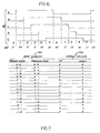
- FIGURE 6 is a view of a divide-by-ten type of pulse trains 600 and a digital code 610 assigned to the pulse trains.
- the pulse trains 600 are offset square waves of a conventional type known in the art, generated from a sinusoidally-varying Moire fringe pattern by a pair of photodetectors and a resistive network.
- FIGURE 7 illustrates a ROM storage technique including a plurality of ROM addresses 710 and a stored value 720 for each address.
- the ROM address 710 includes two bits representative of the present pulse train status and two bits representative of the pulse train status in the immediately preceding state.
- For each ROM address thus created there are two stored values, one a marker or indicator for an "up" count, i.e., an increasing measurement direction, and the other a marker or indicator for a "down" count, i.e., a decrease in the measurement.
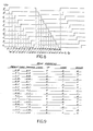
- FIGURES 8-10 show a divide-by-twenty system otherwise similar to that shown in FIGURES 6 and 7.
- FIGURE 8 shows a pulse train scheme and a digital code assignment for such a system.
- FIGURE 9 shows a ROM storage scheme for such a system.
- FIGURE 10 shows a logic diagram 900 for translating the pulses into a ROM address.
- the logic diagram 900 includes two sets 910,920 of five two-input AND gates, each driving a five-input OR gate.
- the first set 910 includes AND gates 911,912,913,914,915 with the output of each AND gate serving as an input to an OR gate 916.
- Each AND gate performs a logic "AND" function on two of the pulse trains of FIGURE 8, with some of the inputs being inverted or negated.
- AND gate 911 provides a logic AND of pulse train C and the negated pulse train E.
- the OR gate 916 has inputs from the AND gates 911, 912,913,914 and 915 and executes an OR function to provide one input to a ROM 930 on a line 931 (indicating a present value D11 as part of the ROM-address and to a dual D flip-flop 940 on a line 941 (to provide a past value on a Q output Q10 of the dual D flip-flop (or latch) 940 in the next period e.g., a D10 part to the ROM address).
- the set 920 of AND gates 921,922,923, 924,925 uses different inputs and have outputs coupled to an OR gate 926 to provide a second digit D21 of the ROM address.
- the dual D flip-flop 940 also provides a delay to generate a D20 input to the address of the ROM.
- a different divisor or digital code could be used to advantage.
- the input measurement signal need not be Moire fringe type nor even optical.
- other forms of memory besides a ROM could be used, e.g., a digital computer, a PROM or a RAM.
- Other types of flip-flops could be used to advantage.
- the digital code might be expanded beyond two digits to provide additional information such as error or transition of more than one count in a single clock signal.
Landscapes
- Physics & Mathematics (AREA)
- General Physics & Mathematics (AREA)
- Length Measuring Devices By Optical Means (AREA)
- Optical Transform (AREA)
- Length Measuring Devices With Unspecified Measuring Means (AREA)
Applications Claiming Priority (2)
| Application Number | Priority Date | Filing Date | Title |
|---|---|---|---|
| US7162579A | 1979-08-31 | 1979-08-31 | |
| US71625 | 1979-08-31 |
Publications (1)
| Publication Number | Publication Date |
|---|---|
| EP0024969A1 true EP0024969A1 (de) | 1981-03-11 |
Family
ID=22102519
Family Applications (1)
| Application Number | Title | Priority Date | Filing Date |
|---|---|---|---|
| EP80401146A Withdrawn EP0024969A1 (de) | 1979-08-31 | 1980-08-01 | Messmaschine und Verfahren zur Erzeugung von Verschiebungsanzeigesignalen in einer solchen Maschine |
Country Status (3)
| Country | Link |
|---|---|
| EP (1) | EP0024969A1 (de) |
| JP (1) | JPS5637504A (de) |
| CA (1) | CA1142345A (de) |
Cited By (4)
| Publication number | Priority date | Publication date | Assignee | Title |
|---|---|---|---|---|
| EP0128519A3 (de) * | 1983-06-14 | 1987-07-01 | Kollmorgen Corporation | Bürstenloser Tachogenerator |
| GB2195762A (en) * | 1986-10-03 | 1988-04-13 | Rank Taylor Hobson Ltd | Interpolator |
| FR2608273A1 (fr) * | 1986-12-16 | 1988-06-17 | Yoshida Kogyo Kk | Procede pour determiner l'angle de rotation d'un corps rotatif |
| EP0770877A1 (de) * | 1995-10-27 | 1997-05-02 | Elan Schaltelemente GmbH | Verfahren zur Überwachung wie Stillstands- und/oder Einrichtungsdrehzahlüberwachung eines Antriebs, insbesondere hochdynamischen Servoantriebs, sowie Lastrelais insbesondere zur Verwendung bei einem entsprechenden Verfahren |
Families Citing this family (1)
| Publication number | Priority date | Publication date | Assignee | Title |
|---|---|---|---|---|
| JPS5948160A (ja) * | 1982-09-14 | 1984-03-19 | Dainippon Printing Co Ltd | 印刷物の走行位置補正方法 |
Citations (5)
| Publication number | Priority date | Publication date | Assignee | Title |
|---|---|---|---|---|
| DE2160247A1 (de) * | 1970-12-07 | 1972-06-22 | Asea Ab | Anordnung zur Zählung vorzeichenbehafteter Impulse |
| US3713139A (en) * | 1971-01-25 | 1973-01-23 | Bendix Corp | Apparatus and method of determining displacements |
| FR2329021A1 (fr) * | 1975-10-25 | 1977-05-20 | Heidenhain Gmbh Dr Johannes | Compteur electronique reversible comportant une memoire morte |
| US4079251A (en) * | 1976-08-12 | 1978-03-14 | Osann Jr Robert | Incremental optical encoder system for absolute position measurement |
| DE2656982A1 (de) * | 1976-12-16 | 1978-06-22 | Ver Flugtechnische Werke | Schaltungsanordnung zur auswertung von impulsfolgen eines digitalen incrementalgebers |
-
1980
- 1980-04-18 CA CA000350207A patent/CA1142345A/en not_active Expired
- 1980-08-01 EP EP80401146A patent/EP0024969A1/de not_active Withdrawn
- 1980-08-30 JP JP11904880A patent/JPS5637504A/ja active Pending
Patent Citations (5)
| Publication number | Priority date | Publication date | Assignee | Title |
|---|---|---|---|---|
| DE2160247A1 (de) * | 1970-12-07 | 1972-06-22 | Asea Ab | Anordnung zur Zählung vorzeichenbehafteter Impulse |
| US3713139A (en) * | 1971-01-25 | 1973-01-23 | Bendix Corp | Apparatus and method of determining displacements |
| FR2329021A1 (fr) * | 1975-10-25 | 1977-05-20 | Heidenhain Gmbh Dr Johannes | Compteur electronique reversible comportant une memoire morte |
| US4079251A (en) * | 1976-08-12 | 1978-03-14 | Osann Jr Robert | Incremental optical encoder system for absolute position measurement |
| DE2656982A1 (de) * | 1976-12-16 | 1978-06-22 | Ver Flugtechnische Werke | Schaltungsanordnung zur auswertung von impulsfolgen eines digitalen incrementalgebers |
Cited By (5)
| Publication number | Priority date | Publication date | Assignee | Title |
|---|---|---|---|---|
| EP0128519A3 (de) * | 1983-06-14 | 1987-07-01 | Kollmorgen Corporation | Bürstenloser Tachogenerator |
| GB2195762A (en) * | 1986-10-03 | 1988-04-13 | Rank Taylor Hobson Ltd | Interpolator |
| US4823000A (en) * | 1986-10-03 | 1989-04-18 | Rank Taylor Hobson Limited | Apparatus for indicating the value of a variable |
| FR2608273A1 (fr) * | 1986-12-16 | 1988-06-17 | Yoshida Kogyo Kk | Procede pour determiner l'angle de rotation d'un corps rotatif |
| EP0770877A1 (de) * | 1995-10-27 | 1997-05-02 | Elan Schaltelemente GmbH | Verfahren zur Überwachung wie Stillstands- und/oder Einrichtungsdrehzahlüberwachung eines Antriebs, insbesondere hochdynamischen Servoantriebs, sowie Lastrelais insbesondere zur Verwendung bei einem entsprechenden Verfahren |
Also Published As
| Publication number | Publication date |
|---|---|
| CA1142345A (en) | 1983-03-08 |
| JPS5637504A (en) | 1981-04-11 |
Similar Documents
| Publication | Publication Date | Title |
|---|---|---|
| CA1203625A (en) | Apparatus for detecting an absolute position and a process thereof | |
| CN100547354C (zh) | 用于绝对位置测量的绝对型圆容栅传感器测量装置 | |
| US4794251A (en) | Apparatus for measuring lengths or angles | |
| EP0042179A2 (de) | Codierer | |
| US4831510A (en) | Encoder and resolver signal processing circuit | |
| EP0042178A2 (de) | Absolutcodierer | |
| US3670324A (en) | Analog-digital shaft position encoder | |
| EP0039082A2 (de) | Verfahren und Einrichtung zum Messen der Verschiebung zwischen einer Kodierplatte und einer Sensoranordnung | |
| EP0287613B1 (de) | Absolutskalenmesssystem | |
| GB2059701A (en) | Apparatus for producing digital electrical signals representative of position | |
| EP0039921B1 (de) | Codiergerät und Verfahren zu seiner Verwendung | |
| CA1142345A (en) | Relatively moving photodiode sensed diffraction grating-type measuring device | |
| GB1569888A (en) | Electronic counting apparatus | |
| JPH11281403A (ja) | 光学式リニヤスケール原点信号発生装置 | |
| US3733472A (en) | Apparatus for the automatic detection of counting errors in a displacement measuring system by encoding and counting | |
| EP0262881B1 (de) | Gerät zum Anzeigen des Wertes einer Variablen | |
| JPH0126003B2 (de) | ||
| KR830001864B1 (ko) | 향상된 안정도를 갖고 측정표시를 주기적으로 발생시키는 장치 | |
| JPH05196451A (ja) | 測長または測角装置 | |
| US3858033A (en) | Inch-metric read-out for a measuring system | |
| JPH0141925B2 (de) | ||
| JP2678386B2 (ja) | 位置検出装置 | |
| JPH0219405B2 (de) | ||
| JP2998314B2 (ja) | アブソリュートスケール装置 | |
| CN218411219U (zh) | 码盘式编码器 |
Legal Events
| Date | Code | Title | Description |
|---|---|---|---|
| PUAI | Public reference made under article 153(3) epc to a published international application that has entered the european phase |
Free format text: ORIGINAL CODE: 0009012 |
|
| 17P | Request for examination filed |
Effective date: 19800807 |
|
| AK | Designated contracting states |
Designated state(s): DE FR GB IT SE |
|
| STAA | Information on the status of an ep patent application or granted ep patent |
Free format text: STATUS: THE APPLICATION IS DEEMED TO BE WITHDRAWN |
|
| 18D | Application deemed to be withdrawn |
Effective date: 19820705 |
|
| RIN1 | Information on inventor provided before grant (corrected) |
Inventor name: TUMBUSH, GERALD LAWRENCE |