EP0024975A1 - Sattelförmiger Seilgreifer mit Führungsgabel und rutschhemmender Vorrichtung für Wagen einer Einseilhängebahn - Google Patents
Sattelförmiger Seilgreifer mit Führungsgabel und rutschhemmender Vorrichtung für Wagen einer Einseilhängebahn Download PDFInfo
- Publication number
- EP0024975A1 EP0024975A1 EP80401182A EP80401182A EP0024975A1 EP 0024975 A1 EP0024975 A1 EP 0024975A1 EP 80401182 A EP80401182 A EP 80401182A EP 80401182 A EP80401182 A EP 80401182A EP 0024975 A1 EP0024975 A1 EP 0024975A1
- Authority
- EP
- European Patent Office
- Prior art keywords
- cable
- harness
- installation according
- fork
- lug
- Prior art date
- Legal status (The legal status is an assumption and is not a legal conclusion. Google has not performed a legal analysis and makes no representation as to the accuracy of the status listed.)
- Granted
Links
- 238000009434 installation Methods 0.000 claims description 14
- 230000008878 coupling Effects 0.000 claims description 13
- 238000010168 coupling process Methods 0.000 claims description 13
- 238000005859 coupling reaction Methods 0.000 claims description 13
- 230000000694 effects Effects 0.000 claims description 5
- 230000010355 oscillation Effects 0.000 claims description 5
- 230000005484 gravity Effects 0.000 claims description 3
- 230000009471 action Effects 0.000 abstract description 5
- 206010012411 Derailment Diseases 0.000 description 2
- 238000005096 rolling process Methods 0.000 description 2
- 238000005452 bending Methods 0.000 description 1
- 238000009432 framing Methods 0.000 description 1
- 238000003780 insertion Methods 0.000 description 1
- 230000037431 insertion Effects 0.000 description 1
- 230000007246 mechanism Effects 0.000 description 1
- 230000035515 penetration Effects 0.000 description 1
- 230000009467 reduction Effects 0.000 description 1
- 230000035945 sensitivity Effects 0.000 description 1
Images

Classifications
-
- B—PERFORMING OPERATIONS; TRANSPORTING
- B61—RAILWAYS
- B61B—RAILWAY SYSTEMS; EQUIPMENT THEREFOR NOT OTHERWISE PROVIDED FOR
- B61B12/00—Component parts, details or accessories not provided for in groups B61B7/00 - B61B11/00
- B61B12/12—Cable grippers; Haulage clips
- B61B12/122—Cable grippers; Haulage clips for aerial ropeways
Definitions
- the invention relates to a continuous cable overhead cable transport installation comprising load support carriages, capable of being coupled to the tractor - carrier cable by harnesses placed on the cable and having reverse V wedging surfaces. which overlap and grip the cable under the effect of the weight of the load transported.
- the object of the present invention is to remedy this drawback.
- each harness is pivotally mounted on the carriage to allow a movement in the vertical plane containing the cable during a lifting of the harness of said cable and that each harness has a fork guide remaining engaged on the cable in the pivoted position of the harness during an untimely lifting of the latter to prevent any stalling of the harness.
- the fork In normal operation, the fork is inactive, its teeth extending parallel to the direction of the cable in the extension of the harnessing surfaces of the harness on the cable.
- the cable emerges from the wedging surfaces in an inverted V and allows the pivoting of the harness bringing the fork into the active, lowered position, straddled on the cable.
- This fork guides the harness which comes to rest automatically on the cable in the coupling position at the end of the oscillation.
- the length of the fork tines must be sufficient to guide the harness during the maximum lifting amplitudes likely to occur during operation.
- the fork latch downward movement is caused by the imbalance between the weight portion ar- "Rière and the front part of the fifth wheel with respect to its pivot axis. This action is accentuated by that of a hairpin spring to increase the speed of movement
- the uncoupling of the load naturally requires a corresponding lifting.
- the fork extends at the rear of the harness to avoid any bending during engagement on the cable, in particular when the load is coupled.
- the assembly is particularly simple and robust and does not require any special locking or control mechanism.
- the harness comprises a movable lug capable of cooperating with the cable to prevent any sliding of the harness on the cable.
- the adhesion of the harness by jamming on the cable may be insufficient on the steep sections and it has already been proposed to increase this adhesion by the use of wedging surfaces at a small angle at the top of the V and / or by striations or pins provided on the surfaces in contact with the cable.
- the reduction of the angle is limited by the obligation to wedge a thinned cable without excessive interlocking, risking obstructing the passage on the pulleys.
- Fixed lugs lose their effectiveness totally or partially on worn cables or due to their own wear, or even when the harness is lifted.
- the movable locking lug By mounting the movable locking lug on the harness, it is ensured that it remains in contact with the cable.
- the edge of the lug in contact with the cable advantageously follows the periphery of the cable and is shaped to be inserted between two strands to increase the locking effect.
- the lug is arranged at the front of the harness so as to be raised in the pivoted position of the harness.
- the load support trolley generally has two coupling harnesses and it is advantageous to determine the spacing between the two harnesses, so that when the lug of one of the harnesses is inserted between two strands of the cable, the lug of the other harness is in abutment on a strand, so as to be assured of the engagement of at least one lug between strands for any relative position of the carriage.
- the rollers or pulleys supporting the cable have laterally grooves in the cable guide groove allowing increased lateral pivoting of the harnesses without risk of contacting the edges of the wedging surfaces with the bottom of the pebble groove.
- This arrangement is particularly advantageous for harnesses with a small angle of wedging surfaces whose penetration depth on the cable varies greatly with the thinning of the cable. This possibility of having smaller angles increases the adhesion of the two surfaces in contact with the cable.
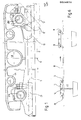
- a tractor-carrier cable 10 of an overhead cable conveyor runs continuously for transporting loads along the line.
- the loads or skips are coupled to the departure station with cable 10 and automatically uncoupled from the arrival station.
- Each bucket is fixed by a hanger of which only the axis 12 is shown, to a carriage 14 by means of a hinge pin 16.
- the carriage 14 comprises two harnesses 18, 20 for coupling to the cable 10, which are pivotally mounted on axes 22, 24 symmetrically of axis 16 and will be described in detail below.
- the carriage 14 further comprises rollers (not shown) capable of rolling on transfer rails in the stations.
- the harnesses 18, 20 are identical and only one 18 is described in detail below, more particularly with reference to FIGS. 3 to 5.
- the body of the harness 18, articulated on the axis 22, has at its base two surfaces wedging 26, 28, or fixed jaws arranged in inverted V to come cover the cable 10 in the coupled position of the harness 18 and tighten the cable 10 under the effect of the weight of the load transported.
- the inclination of the wedging surfaces 26, 28 allows compensation for wear or thinning of the cable 10 and is determined to obtain a maximum wedging force for a given load.
- the wedging surfaces 26, 28 extend behind the harness 18 by two teeth 30, 32 forming a fork capable of framing the cable 10. In the coupling position, shown in the figures, the teeth 30, 32 extend in the longitudinal direction of the cable 10, without increasing the clearance gauge on the support rollers.
- the device works as follows:
- the carriage 14 is brought into line with the cable 10 and by rolling on an inclined rail is placed on the cable 10.
- the harnesses 18, 20 tightened on the cable 10 provide support and training for the load and from the carriage 14 towards the arrival station where the uncoupling takes place automatically by a ramp which lifts the carriage 14.
- the carriage 14 inadvertently lifts during the journey, in particular during an oscillation of the cable 10 towards the position 10 ', the wedging surfaces 26, 28 are released from the cable.
- the harnesses 18, 20 pivot in a counterclockwise direction (FIG. 1) downwards, the cable 10 'remaining trapped in the forks 30, 32.
- the lift of the carriage 14 must be sufficient to release the cable from the forks 30, 32.
- the length of the forks 30, 32 is chosen according to the maximum lift heights of the carriage 14 to avoid any risk of derailment .
- the forks 30, 32 can contribute to guiding the carriage 14 during coupling or uncoupling.
- a pin 34 On the anterior portion 36 of the wheel 18, 20 is slidably mounted a pin 34, within a housing sen - siblement vertical in the fifth wheel coupling position (fig. 2).
- the upper part of the lug 34 carries a head 38 limiting the sinking of the lug 34 and subjected to the action of a leaf spring 40, which pushes the lug 34 to the bottom of its housing.
- the lower part of the lug 34 is shaped as an edge 42 which opens into the bottom of the groove confined by the wedging surfaces 26, 28.
- the edge 42 cooperates with the upper face of the cable 10 engaged between the surfaces 26, 28 and the edge 42 is inclined relative to the axis of the cable 10 by an angle corresponding to the slope of the strands of the cable 10 to allow its insertion between two successive strands.
- the edge 44 of the edge 42 is concave to match the circumference of the cable.
- the stroke of the lug 34 is sufficient to maintain in any case the contact with the cable clamped between the surfaces 26, 28.
- the presence of the lug 38 increases the grip of the harness and allows the crossing of sections with a steep slope.
- the articulation of the harnesses 18, 20 on the carriage 14 avoids any engagement of the lug 34 prior to coupling by wedging between the surfaces 26, 28 and therefore any wear by friction on the cable.
- the spacing of the axes 22, 24 of articulation of the harnesses 18, 20 is determined as a function of the pitch of the helix of the strands of the cable 10, so as to always have at least one of the lugs 34 engaged between strands.
- the lug 34 can easily be replaced in the event of wear and thanks to its mobility it ensures the locking function even on a thinned cable.
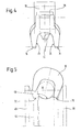
- FIG. 5 there is seen a groove profile of a roller 46 for supporting the cable 10, designed to facilitate the passage of the coupling harnesses 18, 20.
- the cable 10, shown in FIG. 5, is thinned and at the wear limit and the fifth wheel 18 rests practically by its bottom on the cable 10.
- the roller 46 has a central groove 48 for guiding the cable 10 framed on the side and other of grooves 50, 52, the spacing of which corresponds to the spacing of the lower edges 54, 56 of the fixed clamping jaws with wedging surface 26, 28.
- the grooves 50, 52 are delimited laterally by the flanges 58, 60 in the usual manner.
- the assembly is arranged so that only the central position of the cable 10, shown in FIG.
Landscapes
- Engineering & Computer Science (AREA)
- Transportation (AREA)
- Mechanical Engineering (AREA)
- Forklifts And Lifting Vehicles (AREA)
- Electric Cable Installation (AREA)
- Braking Arrangements (AREA)
- Paper (AREA)
- Current-Collector Devices For Electrically Propelled Vehicles (AREA)
- Relays Between Conveyors (AREA)
- Feeding, Discharge, Calcimining, Fusing, And Gas-Generation Devices (AREA)
- Ropes Or Cables (AREA)
- Crystals, And After-Treatments Of Crystals (AREA)
- Storing, Repeated Paying-Out, And Re-Storing Of Elongated Articles (AREA)
- Load-Engaging Elements For Cranes (AREA)
Priority Applications (1)
| Application Number | Priority Date | Filing Date | Title |
|---|---|---|---|
| AT80401182T ATE4039T1 (de) | 1979-08-27 | 1980-08-12 | Sattelfoermiger seilgreifer mit fuehrungsgabel und rutschhemmender vorrichtung fuer wagen einer einseilhaengebahn. |
Applications Claiming Priority (2)
| Application Number | Priority Date | Filing Date | Title |
|---|---|---|---|
| FR7921623A FR2464170A1 (fr) | 1979-08-27 | 1979-08-27 | Sellettes a fourche de guidage et a dispositif anti-glissement pour wagonnets de transporteur aerien monocable |
| FR7921623 | 1979-08-27 |
Publications (2)
| Publication Number | Publication Date |
|---|---|
| EP0024975A1 true EP0024975A1 (de) | 1981-03-11 |
| EP0024975B1 EP0024975B1 (de) | 1983-07-06 |
Family
ID=9229162
Family Applications (1)
| Application Number | Title | Priority Date | Filing Date |
|---|---|---|---|
| EP80401182A Expired EP0024975B1 (de) | 1979-08-27 | 1980-08-12 | Sattelförmiger Seilgreifer mit Führungsgabel und rutschhemmender Vorrichtung für Wagen einer Einseilhängebahn |
Country Status (9)
| Country | Link |
|---|---|
| US (1) | US4364314A (de) |
| EP (1) | EP0024975B1 (de) |
| JP (1) | JPS5634562A (de) |
| AT (1) | ATE4039T1 (de) |
| BR (1) | BR8005330A (de) |
| DE (1) | DE3064041D1 (de) |
| FR (1) | FR2464170A1 (de) |
| IN (1) | IN153938B (de) |
| YU (1) | YU211280A (de) |
Families Citing this family (4)
| Publication number | Priority date | Publication date | Assignee | Title |
|---|---|---|---|---|
| FR2549430B1 (fr) * | 1983-07-21 | 1986-03-21 | Grenoble Inst Nal Polytechni | Dispositif de fixation d'une telecabine ou d'un telesiege sur un cable muni d'une surface de roulement pour galets |
| US4658733A (en) * | 1985-08-19 | 1987-04-21 | Kunczynski Jan K | Aerial tramway grip assembly |
| US4860664A (en) * | 1985-08-19 | 1989-08-29 | Zygmunt A. Kunczynski | Haul rope grip assembly for aerial tramway with elastic block jaw actuating means |
| JP2511035B2 (ja) * | 1986-05-12 | 1996-06-26 | ポマガルスキイ ソシエテ アノニム | 空中ケ−ブル輸送装置 |
Citations (6)
| Publication number | Priority date | Publication date | Assignee | Title |
|---|---|---|---|---|
| DE78956C (de) * | ROPEWAYS SYNDICATE LTD., London | Seilgreifer für Hängebahnwagen | ||
| FR1455899A (fr) * | 1965-05-20 | 1966-10-21 | Pomagalski Jean Sa | Attache embrayable et débrayable pour installations de transport ou de remorquage par câble aérien |
| AT321357B (de) * | 1970-06-26 | 1975-03-25 | Senn Dipl Ing Dr Techn Eduard | Gehänge mit einem Laufwerk und zwei Klemmapparaten Zum An- und Abkuppeln des Gehänges |
| FR2257508A1 (en) * | 1973-09-04 | 1975-08-08 | David Henri | Overhead cable conveyor saddle - has compression springs to absorb shocks caused by passing over pulleys |
| FR2264695A1 (en) * | 1974-03-22 | 1975-10-17 | Baudin Chateauneuf | Cable connection for cable car - has pivotal and sliding blocks in bogie supporting cable |
| AT337249B (de) * | 1970-06-26 | 1977-06-27 | Senn Dipl Ing Dr Techn Eduard | Gehange mit einem laufwerk und zwei klemmapparaten zum an- und abkuppeln des gehanges |
Family Cites Families (6)
| Publication number | Priority date | Publication date | Assignee | Title |
|---|---|---|---|---|
| US530902A (en) * | 1894-12-11 | John pearce roe | ||
| US338615A (en) * | 1886-03-23 | bedling-ton | ||
| US444408A (en) * | 1891-01-06 | Bucket-clip for wire-rope tramways | ||
| US438949A (en) * | 1890-10-21 | Appakatus for transporting loads by means of traveling | ||
| US1364208A (en) * | 1919-04-22 | 1921-01-04 | Rennie William | Trolley |
| US1391741A (en) * | 1920-07-22 | 1921-09-27 | Christian E Liebenberg | Trolley-wheel |
-
1979
- 1979-08-27 FR FR7921623A patent/FR2464170A1/fr active Granted
-
1980
- 1980-08-11 US US06/176,801 patent/US4364314A/en not_active Expired - Lifetime
- 1980-08-12 AT AT80401182T patent/ATE4039T1/de not_active IP Right Cessation
- 1980-08-12 EP EP80401182A patent/EP0024975B1/de not_active Expired
- 1980-08-12 DE DE8080401182T patent/DE3064041D1/de not_active Expired
- 1980-08-21 JP JP11410880A patent/JPS5634562A/ja active Pending
- 1980-08-22 BR BR8005330A patent/BR8005330A/pt unknown
- 1980-08-25 YU YU02112/80A patent/YU211280A/xx unknown
- 1980-08-26 IN IN978/CAL/80A patent/IN153938B/en unknown
Patent Citations (6)
| Publication number | Priority date | Publication date | Assignee | Title |
|---|---|---|---|---|
| DE78956C (de) * | ROPEWAYS SYNDICATE LTD., London | Seilgreifer für Hängebahnwagen | ||
| FR1455899A (fr) * | 1965-05-20 | 1966-10-21 | Pomagalski Jean Sa | Attache embrayable et débrayable pour installations de transport ou de remorquage par câble aérien |
| AT321357B (de) * | 1970-06-26 | 1975-03-25 | Senn Dipl Ing Dr Techn Eduard | Gehänge mit einem Laufwerk und zwei Klemmapparaten Zum An- und Abkuppeln des Gehänges |
| AT337249B (de) * | 1970-06-26 | 1977-06-27 | Senn Dipl Ing Dr Techn Eduard | Gehange mit einem laufwerk und zwei klemmapparaten zum an- und abkuppeln des gehanges |
| FR2257508A1 (en) * | 1973-09-04 | 1975-08-08 | David Henri | Overhead cable conveyor saddle - has compression springs to absorb shocks caused by passing over pulleys |
| FR2264695A1 (en) * | 1974-03-22 | 1975-10-17 | Baudin Chateauneuf | Cable connection for cable car - has pivotal and sliding blocks in bogie supporting cable |
Also Published As
| Publication number | Publication date |
|---|---|
| BR8005330A (pt) | 1981-03-04 |
| YU211280A (en) | 1984-02-29 |
| JPS5634562A (en) | 1981-04-06 |
| ATE4039T1 (de) | 1983-07-15 |
| EP0024975B1 (de) | 1983-07-06 |
| US4364314A (en) | 1982-12-21 |
| IN153938B (de) | 1984-09-01 |
| FR2464170B1 (de) | 1983-05-13 |
| FR2464170A1 (fr) | 1981-03-06 |
| DE3064041D1 (en) | 1983-08-11 |
Similar Documents
| Publication | Publication Date | Title |
|---|---|---|
| EP0114129B2 (de) | Vorrichtung zum Regulieren des Abstands von schaltbaren Seilbahnkabinen oder Sesselliften | |
| CA2820145C (fr) | Siege de remontee mecanique avec verrouillage magnetique de garde-corps | |
| FR2480631A1 (fr) | Procede de tri ou de transport et installation et chariot pour sa mise en oeuvre | |
| CH617892A5 (de) | ||
| EP0170587B1 (de) | Sitze- oder Kabinenantriebsvorrichtung für Seilbahnstationen | |
| EP0056919B1 (de) | Sesselbahn oder Kabinenbahn mit lösbaren Klemmen | |
| EP2384963A1 (de) | Unterwasserverbindungsstück zur Verbindung einer Erdölanlage, das mit einer Trennschutzvorrichtung ausgestattet ist | |
| EP0024975B1 (de) | Sattelförmiger Seilgreifer mit Führungsgabel und rutschhemmender Vorrichtung für Wagen einer Einseilhängebahn | |
| EP2780209B1 (de) | Mechanisches hubfahrzeug | |
| FR2591174A1 (fr) | Installation de transport a cables aeriens dont les vehicules sont associes aux cables par au moins deux suspentes | |
| EP2663481B1 (de) | Vorrichtung zur verbindung elektrischer leiter an bord eines mechanischen hubfahrzeugs | |
| FR2706404A1 (fr) | Installation de téléski. | |
| EP0055955A1 (de) | Drahtseilbahn mit Trag- und Zugseil | |
| WO2014114890A1 (fr) | Ensemble de connexion sous-marin et methode de connexion | |
| EP0227508B1 (de) | Schienengebundene Transportinstallation mit einer Sicherheitsvorrichtung zur Notbremsung wenigstens eines kabelgezogenen Transportfahrzeugs | |
| FR2916211A1 (fr) | Installation pour la pose de caniveaux et de couvercles | |
| EP0842837B1 (de) | Transportanlage mit Luftseil und kuppelbaren Seilklemmen mit Mitteln zum Messen der Klemmkraft der Seilklemmen | |
| EP0192504A1 (de) | Seilbahn mit zwei tragfähigen Förderseilen | |
| EP0769626A1 (de) | Verriegelbarer Haken mit mechanischer Speicherung | |
| EP0265355A1 (de) | Greiferwagen für Doppelkabelbahn | |
| FR2725416A1 (fr) | Convoyeur aerien monorail muni d'un dispositif d'accrochage et de decrochage des charges | |
| FR2586985A1 (fr) | Procede de telepherage et telepherique pour sa mise en oeuvre | |
| FR2586986A1 (fr) | Chariot d'accouplement au cable d'une telecabine ou d'un telesiege | |
| FR2730692A1 (fr) | Installation de transport par cables | |
| FR2648795A1 (fr) | Dispositif pour solidariser ou desolidariser une suspente a un cable sans fin dans une installation de transport de charge |
Legal Events
| Date | Code | Title | Description |
|---|---|---|---|
| PUAI | Public reference made under article 153(3) epc to a published international application that has entered the european phase |
Free format text: ORIGINAL CODE: 0009012 |
|
| AK | Designated contracting states |
Designated state(s): AT CH DE GB IT |
|
| 17P | Request for examination filed |
Effective date: 19810908 |
|
| ITF | It: translation for a ep patent filed | ||
| GRAA | (expected) grant |
Free format text: ORIGINAL CODE: 0009210 |
|
| AK | Designated contracting states |
Designated state(s): AT CH DE GB IT LI |
|
| REF | Corresponds to: |
Ref document number: 4039 Country of ref document: AT Date of ref document: 19830715 Kind code of ref document: T |
|
| REF | Corresponds to: |
Ref document number: 3064041 Country of ref document: DE Date of ref document: 19830811 |
|
| PLBE | No opposition filed within time limit |
Free format text: ORIGINAL CODE: 0009261 |
|
| STAA | Information on the status of an ep patent application or granted ep patent |
Free format text: STATUS: NO OPPOSITION FILED WITHIN TIME LIMIT |
|
| 26N | No opposition filed | ||
| PGFP | Annual fee paid to national office [announced via postgrant information from national office to epo] |
Ref country code: DE Payment date: 19840808 Year of fee payment: 5 |
|
| PGFP | Annual fee paid to national office [announced via postgrant information from national office to epo] |
Ref country code: CH Payment date: 19840820 Year of fee payment: 5 |
|
| PGFP | Annual fee paid to national office [announced via postgrant information from national office to epo] |
Ref country code: AT Payment date: 19860821 Year of fee payment: 7 |
|
| PG25 | Lapsed in a contracting state [announced via postgrant information from national office to epo] |
Ref country code: GB Free format text: LAPSE BECAUSE OF NON-PAYMENT OF DUE FEES Effective date: 19880812 Ref country code: AT Effective date: 19880812 |
|
| PG25 | Lapsed in a contracting state [announced via postgrant information from national office to epo] |
Ref country code: LI Effective date: 19880831 Ref country code: CH Effective date: 19880831 |
|
| REG | Reference to a national code |
Ref country code: CH Ref legal event code: PL |
|
| PG25 | Lapsed in a contracting state [announced via postgrant information from national office to epo] |
Ref country code: DE Effective date: 19890503 |
|
| GBPC | Gb: european patent ceased through non-payment of renewal fee |