EP0025005A1 - Dispositif pour débiter et doser des quantités minimes de liquide - Google Patents
Dispositif pour débiter et doser des quantités minimes de liquide Download PDFInfo
- Publication number
- EP0025005A1 EP0025005A1 EP80730057A EP80730057A EP0025005A1 EP 0025005 A1 EP0025005 A1 EP 0025005A1 EP 80730057 A EP80730057 A EP 80730057A EP 80730057 A EP80730057 A EP 80730057A EP 0025005 A1 EP0025005 A1 EP 0025005A1
- Authority
- EP
- European Patent Office
- Prior art keywords
- membrane
- passage opening
- piezoceramic
- storage container
- opening
- Prior art date
- Legal status (The legal status is an assumption and is not a legal conclusion. Google has not performed a legal analysis and makes no representation as to the accuracy of the status listed.)
- Withdrawn
Links
Images

Classifications
-
- A—HUMAN NECESSITIES
- A61—MEDICAL OR VETERINARY SCIENCE; HYGIENE
- A61M—DEVICES FOR INTRODUCING MEDIA INTO, OR ONTO, THE BODY; DEVICES FOR TRANSDUCING BODY MEDIA OR FOR TAKING MEDIA FROM THE BODY; DEVICES FOR PRODUCING OR ENDING SLEEP OR STUPOR
- A61M5/00—Devices for bringing media into the body in a subcutaneous, intra-vascular or intramuscular way; Accessories therefor, e.g. filling or cleaning devices, arm rests
- A61M5/14—Infusion devices, e.g. infusing by gravity; Blood infusion; Accessories therefor
- A61M5/142—Pressure infusion, e.g. using pumps
- A61M5/14244—Pressure infusion, e.g. using pumps adapted to be carried by the patient, e.g. portable on the body
- A61M5/14276—Pressure infusion, e.g. using pumps adapted to be carried by the patient, e.g. portable on the body specially adapted for implantation
-
- F—MECHANICAL ENGINEERING; LIGHTING; HEATING; WEAPONS; BLASTING
- F04—POSITIVE - DISPLACEMENT MACHINES FOR LIQUIDS; PUMPS FOR LIQUIDS OR ELASTIC FLUIDS
- F04B—POSITIVE-DISPLACEMENT MACHINES FOR LIQUIDS; PUMPS
- F04B43/00—Machines, pumps, or pumping installations having flexible working members
- F04B43/02—Machines, pumps, or pumping installations having flexible working members having plate-like flexible members, e.g. diaphragms
- F04B43/04—Pumps having electric drive
- F04B43/043—Micropumps
- F04B43/046—Micropumps with piezoelectric drive
-
- H—ELECTRICITY
- H10—SEMICONDUCTOR DEVICES; ELECTRIC SOLID-STATE DEVICES NOT OTHERWISE PROVIDED FOR
- H10N—ELECTRIC SOLID-STATE DEVICES NOT OTHERWISE PROVIDED FOR
- H10N30/00—Piezoelectric or electrostrictive devices
- H10N30/20—Piezoelectric or electrostrictive devices with electrical input and mechanical output, e.g. functioning as actuators or vibrators
- H10N30/204—Piezoelectric or electrostrictive devices with electrical input and mechanical output, e.g. functioning as actuators or vibrators using bending displacement, e.g. unimorph, bimorph or multimorph cantilever or membrane benders
- H10N30/2047—Membrane type
-
- A—HUMAN NECESSITIES
- A61—MEDICAL OR VETERINARY SCIENCE; HYGIENE
- A61M—DEVICES FOR INTRODUCING MEDIA INTO, OR ONTO, THE BODY; DEVICES FOR TRANSDUCING BODY MEDIA OR FOR TAKING MEDIA FROM THE BODY; DEVICES FOR PRODUCING OR ENDING SLEEP OR STUPOR
- A61M2205/00—General characteristics of the apparatus
- A61M2205/02—General characteristics of the apparatus characterised by a particular materials
- A61M2205/0211—Ceramics
-
- A—HUMAN NECESSITIES
- A61—MEDICAL OR VETERINARY SCIENCE; HYGIENE
- A61M—DEVICES FOR INTRODUCING MEDIA INTO, OR ONTO, THE BODY; DEVICES FOR TRANSDUCING BODY MEDIA OR FOR TAKING MEDIA FROM THE BODY; DEVICES FOR PRODUCING OR ENDING SLEEP OR STUPOR
- A61M2205/00—General characteristics of the apparatus
- A61M2205/02—General characteristics of the apparatus characterised by a particular materials
- A61M2205/0238—General characteristics of the apparatus characterised by a particular materials the material being a coating or protective layer
-
- A—HUMAN NECESSITIES
- A61—MEDICAL OR VETERINARY SCIENCE; HYGIENE
- A61M—DEVICES FOR INTRODUCING MEDIA INTO, OR ONTO, THE BODY; DEVICES FOR TRANSDUCING BODY MEDIA OR FOR TAKING MEDIA FROM THE BODY; DEVICES FOR PRODUCING OR ENDING SLEEP OR STUPOR
- A61M2205/00—General characteristics of the apparatus
- A61M2205/02—General characteristics of the apparatus characterised by a particular materials
- A61M2205/0272—Electro-active or magneto-active materials
- A61M2205/0294—Piezoelectric materials
Definitions
- the invention relates to a device for conveying and dosing the smallest amounts of liquid, in particular for use in the human or animal body, consisting of a piezoceramic coated membrane, with its edge on all sides against a rigid wall abuts, the pump chamber thus formed having a passage opening which can be closed by appropriate means.
- diabetes mellitus diabetes mellitus
- some diseases such as diabetes in particular, this is aggravated by the fact that the medication requirement is subject to time fluctuations, so that a time-independent dosage with a constant delivery rate is not an adequate solution.
- the insulin requirement of the diabetic due to the rhythm of meals, work, rest, etc., is subject to large fluctuations during the day.
- the necessary rates for an insulin concentration of 500 IU / ml are on the order of a few microliters per hour.
- a diaphragm pump is used, consisting of a retaining ring and two metal membranes coated with piezoceramic on the outside of the pump.
- An electromagnetic 3-way valve is used to control the flow of medication. Due to the high power consumption of such valves and the already mentioned risk of failure, this concept cannot be used for an implantable system.
- the invention specified in claim 1 is based on the object of developing a device of the type mentioned above, which is capable of conveying the smallest and precisely metered liquid volumes with short response times regardless of the back pressure occurring in the surrounding body environment, with a high level of wear resistance and patient safety must be guaranteed at all times.
- the invention is based on the knowledge that the membrane can form an additional seal that increases operational safety in the idle state, which results in the possibility of a particularly compact design with the advantageous inclusion of further components in the membrane.
- a defined volume is thus removed from the storage container and delivered to the body with the aid of two diaphragms glued on both sides with piezoceramic together with a fixed partition wall, and delivered to the body without the need for further valves.
- a membrane glued in this way is used together with a fixed partition, with a self-closing valve taking on the function of a return seal. The valve does not require any electrical energy and even in the event of a failure, no liquid can escape from the storage container in an uncontrolled manner.
- the passage opening in the membrane is advantageously designed as a flow resistance, for which a membrane filter is preferably suitable.
- the device is both implanted in both versions and can be used in a variety of ways for external use.
- the low weight and low electrical consumption are particularly advantageous trical energy and a high degree of safety for the patient, since the system is securely closed in its rest position, as a result of which no liquid can get out of the body into the storage vessel or vice versa.
- the delivery volume is determined solely by the deflection of the membrane, which is proportional to the voltage applied to the piezoceramic, and is therefore only dependent on this voltage.
- the pump chamber is thus determined solely by the space formed between the membrane and the rigid wall, in which the amount present in this space is conveyed practically without residue.
- the dosage can thus be determined extremely precisely and independently of external influences.
- a storage container 1 for the medicament to be dosed which is not shown completely, is arranged on the left in the figure, while it adjoins the body milieu 21 on the right side or to an outflow catheter connected.
- a membrane 7 and 8 which is preferably made of metal, is located on each side of a partition 2 made of ceramic, which can also be made of any other material that is compatible with the body and medication.
- the two membranes can, however, also be made of a drug and body-compatible plastic such as PTFE, etc. They carry a bonded disc 3 to 6 on both sides, which is made of piezoceramic materials.
- the panes are each provided with a conductive layer on their flat surfaces. When a voltage is applied between these surfaces, they expand in the radial direction and the membrane connected to them experiences a corresponding curvature.
- the membranes each have an embossed bead 22 which runs tangentially between the bonded ceramic and the clamping 14 and which serves to ensure optimum deflection of the membrane by material flowing out of the bead with radial expansion or contraction of the piezoceramic disks.
- the discs glued on both sides cause a greater deflection of the membrane compared to a membrane provided with piezoceramic on one side only.
- the two inner ceramic disks 4, 5 together with the partition 2 perform a sealing effect.
- Two membrane filters 9, 10 placed on the outside are attached to the two holes 11 penetrating the ceramic disks 12 and the membrane lying between them.
- These are preferably made of PTFE with a porosity of 2 / um.
- other medicinal and body-compatible materials can also be used.
- the membrane filters serve both as flow resistance and as bacteriological filters.
- Another bore 13 is arranged in the partition 2 offset from the two bores 11, 12.
- the two membranes 7 and 8 with the glued-on ceramic disks 3 to 6 are provided on both sides and the bores 11 and 12 are provided with a coating of tetrafluoroethylene on the inside.
- other protective coatings are also suitable if they meet the medical requirements.
- the cutting disc 2 can be coated either before or after assembly and the clamping 14 together with the membranes.
- the liquid to be dosed is located in the storage container 1. It is preferably under a certain pressure, which is either applied by the container being designed as an overpressure accumulator, or else the pressure is generated by spring force or the like. generated.
- the membrane 7 Due to the overpressure in the storage vessel 1, the membrane 7 is pressed sealingly against the bore 13, even without an electrical voltage being applied to the piezoceramic 3, 4, so that the partition 2 is closed.
- One The outer membrane 8 forms a further closure between the storage vessel 1 and the body environment 21, an additional contact pressure between the membrane 8 and the cutting disc 2 being able to be brought about here by prestressing the membrane. (If the interior of the storage vessel 1 is not to be under pressure during operation, the membrane 7 can also be preloaded accordingly.)
- This construction prevents the liquid stored in the storage vessel from failing under all circumstances by failure of the control of the piezoceramic drives gets unhindered access to the body. In this way, the system ensures optimal patient safety.
- the liquid When relaxing (Fig. 4), which can be supported by opposite polarization of the ceramic discs 5, 6, the liquid is then expelled into the body environment, since the bore 13 is now closed by the membrane 7 (arrow in Fig. 4).
- the amount of liquid remaining in the bore 12 is protected against contamination by the membrane filter 10, which is preferably made of PTFE, against the body environment.
- the voltage pulses are caused by voltage generator means (not shown) which can emit the necessary voltage pulses of opposite polarity in an alternating sequence, as is evident from the description above.
- the pumping direction can easily be reversed for other applications by reversing the order of actuation of the membranes.
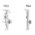
- FIGS. 5 and 6 Components that the Figu ren correspond, are provided with corresponding reference numerals, which also contain a "'".
- the membrane 8 is replaced in this device by a self-closing valve which is attached to the end of a bore 13 '.
- FIG. 5 corresponds to that shown in FIG. 2 for the previously described embodiment.
- the resulting volume is filled through the membrane filter 9 'and the bore 11' with liquid from the reservoir 1 '(arrow in Fig. 5).
- the outlet 13 'to the body side is closed by the valve.
- FIGS. 5 and 6 reproduced in a schematic representation and consists of the valve housing 15, with openings 16 for liquid outlet, made of a body-compatible material or coated with such a material, and provided with a bore 20 for volume compensation during the movement of the valve body 17.
- a ring permanent magnet 18 is arranged, which is made, for example, of a material based on Co / rare earths.
- the valve body 17 consists of a body-compatible material, such as PTFE-coated bar magnet, which is mounted in reverse polarity with respect to the ring magnet, so that the valve is in the rest position, i.e. without external forces, is kept closed by the repulsive forces between the two magnets.
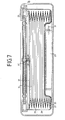
- FIG. 7 shows an embodiment of the dosing device according to the invention as used in an implantable artificial pancreas.
- a hermetically sealed metal housing 22 is next to a separate housing.
- the connecting hose 29 is designed to be elastic so that it only has a slight resistance to the deflection of the membrane opposes.
- the pressure present in the insulin reservoir does not act on the entire surface of the diaphragm pump, but is only exerted in the area of the passage 9 ′′. This means that what is required for the deflection of the inner diaphragm in each pump stroke remains Power so small that it does not overwhelm the relatively small energy reserves in an implantable unit.
- the pump according to the invention forms part of the hermetically sealed outer housing, so that there are no further problems for housing implementation of an outlet for the amount of insulin dispensed.
- the multiple encapsulation chosen is otherwise in accordance with the requirement for the greatest possible patient safety, which must be protected in any case from a larger, uncontrolled amount of insulin.
- the electrical feedthroughs 31 and 32 are also leak-tight, so that extensive security against escaping liquid is also provided here.
Landscapes
- Engineering & Computer Science (AREA)
- Health & Medical Sciences (AREA)
- Hematology (AREA)
- Anesthesiology (AREA)
- Biomedical Technology (AREA)
- Heart & Thoracic Surgery (AREA)
- Vascular Medicine (AREA)
- Life Sciences & Earth Sciences (AREA)
- Animal Behavior & Ethology (AREA)
- General Health & Medical Sciences (AREA)
- Public Health (AREA)
- Veterinary Medicine (AREA)
- Mechanical Engineering (AREA)
- General Engineering & Computer Science (AREA)
- Infusion, Injection, And Reservoir Apparatuses (AREA)
Applications Claiming Priority (2)
| Application Number | Priority Date | Filing Date | Title |
|---|---|---|---|
| DE2933799 | 1979-08-18 | ||
| DE2933799A DE2933799C3 (de) | 1979-08-18 | 1979-08-18 | Vorrichtung zur Förderung und Dosierung kleinster Flüssigkeitsmengen |
Publications (1)
| Publication Number | Publication Date |
|---|---|
| EP0025005A1 true EP0025005A1 (fr) | 1981-03-11 |
Family
ID=6078940
Family Applications (1)
| Application Number | Title | Priority Date | Filing Date |
|---|---|---|---|
| EP80730057A Withdrawn EP0025005A1 (fr) | 1979-08-18 | 1980-08-18 | Dispositif pour débiter et doser des quantités minimes de liquide |
Country Status (2)
| Country | Link |
|---|---|
| EP (1) | EP0025005A1 (fr) |
| DE (1) | DE2933799C3 (fr) |
Cited By (9)
| Publication number | Priority date | Publication date | Assignee | Title |
|---|---|---|---|---|
| WO1988005314A1 (fr) * | 1987-01-27 | 1988-07-28 | Kabivitrum Ab | Pompe et dispositif a perfusion comportant une pompe |
| GB2248891A (en) * | 1990-10-18 | 1992-04-22 | Westonbridge Int Ltd | Membrane micropump |
| US5205819A (en) * | 1989-05-11 | 1993-04-27 | Bespak Plc | Pump apparatus for biomedical use |
| WO1995019502A1 (fr) * | 1994-01-14 | 1995-07-20 | Westonbridge International Limited | Micropompe |
| EP0672834A1 (fr) * | 1994-02-17 | 1995-09-20 | Forschungszentrum Rossendorf e.V. | Micro-manipulateur pour fluides |
| EP0668500A3 (fr) * | 1994-02-17 | 1998-06-17 | Forschungszentrum Rossendorf e.V. | Microanalysateur chimique |
| EP1037680A4 (fr) * | 1997-11-13 | 2001-02-21 | Ronald E Bowden | Conception de coeur artificiel |
| EP2072819A1 (fr) | 2007-12-21 | 2009-06-24 | PARItec GmbH | Chambre de pompe et procédé de fabrication de cette chambre |
| CN111363665A (zh) * | 2020-04-30 | 2020-07-03 | 上海璟良生物工程技术有限公司 | 输送装置及具有该输送装置的生物反应设备 |
Families Citing this family (6)
| Publication number | Priority date | Publication date | Assignee | Title |
|---|---|---|---|---|
| DE3320443C2 (de) * | 1983-06-06 | 1994-08-18 | Siemens Ag | Flüssigkeitspumpe |
| DE3420818A1 (de) * | 1984-05-30 | 1986-01-30 | Andreas Dr. 1000 Berlin Kage | Verfahren zur dosierung von elutionsmitteln in der hplc durch flow-feedback mittels eines dosierventils und eines elutionsmittelunabhaengigen flussmesssystems |
| JP4718691B2 (ja) * | 2001-01-19 | 2011-07-06 | 日機装株式会社 | ダイアフラムポンプ |
| DE10160401A1 (de) * | 2001-11-06 | 2003-05-15 | Consens Gmbh | Membranpumpe mit Piezo-Antrieb |
| US9717298B1 (en) * | 2013-08-26 | 2017-08-01 | Raymond Louis Barrett, Jr. | MEMS valve actuator system |
| CN109821093B (zh) * | 2019-03-01 | 2021-03-12 | 浙江师范大学 | 一种压电堆驱动的输液装置 |
Citations (9)
| Publication number | Priority date | Publication date | Assignee | Title |
|---|---|---|---|---|
| US3107630A (en) * | 1955-01-31 | 1963-10-22 | Textron Inc | Non-magnetic electro-hydraulic pump |
| US3270672A (en) * | 1963-12-23 | 1966-09-06 | Union Oil Co | Pump apparatus |
| US3361067A (en) * | 1966-09-09 | 1968-01-02 | Nasa Usa | Piezoelectric pump |
| DE1453655A1 (de) * | 1962-08-17 | 1971-03-18 | Physics Internat Co | Pumpen durch piezoelektrische Wirkung |
| US3587328A (en) * | 1969-06-05 | 1971-06-28 | Hercules Inc | A fluid-jet deflection type instrument having a diaphragm type pump with piezoelectric actuation |
| US3606592A (en) * | 1970-05-20 | 1971-09-20 | Bendix Corp | Fluid pump |
| US3763385A (en) * | 1970-08-05 | 1973-10-02 | Univ Illinois | Modulator apparatus utilizing piezoelectric plates |
| DE2354249A1 (de) * | 1973-04-25 | 1974-11-14 | Original Odhner Ab | Pumpvorrichtung, bestehend aus einer mit einem piezo-elektrischen kristall verbundenen membran |
| FR2272686A1 (fr) * | 1974-02-04 | 1975-12-26 | Alza Corp |
-
1979
- 1979-08-18 DE DE2933799A patent/DE2933799C3/de not_active Expired
-
1980
- 1980-08-18 EP EP80730057A patent/EP0025005A1/fr not_active Withdrawn
Patent Citations (9)
| Publication number | Priority date | Publication date | Assignee | Title |
|---|---|---|---|---|
| US3107630A (en) * | 1955-01-31 | 1963-10-22 | Textron Inc | Non-magnetic electro-hydraulic pump |
| DE1453655A1 (de) * | 1962-08-17 | 1971-03-18 | Physics Internat Co | Pumpen durch piezoelektrische Wirkung |
| US3270672A (en) * | 1963-12-23 | 1966-09-06 | Union Oil Co | Pump apparatus |
| US3361067A (en) * | 1966-09-09 | 1968-01-02 | Nasa Usa | Piezoelectric pump |
| US3587328A (en) * | 1969-06-05 | 1971-06-28 | Hercules Inc | A fluid-jet deflection type instrument having a diaphragm type pump with piezoelectric actuation |
| US3606592A (en) * | 1970-05-20 | 1971-09-20 | Bendix Corp | Fluid pump |
| US3763385A (en) * | 1970-08-05 | 1973-10-02 | Univ Illinois | Modulator apparatus utilizing piezoelectric plates |
| DE2354249A1 (de) * | 1973-04-25 | 1974-11-14 | Original Odhner Ab | Pumpvorrichtung, bestehend aus einer mit einem piezo-elektrischen kristall verbundenen membran |
| FR2272686A1 (fr) * | 1974-02-04 | 1975-12-26 | Alza Corp |
Non-Patent Citations (2)
| Title |
|---|
| IEEE TRANS. ON SONICS AND ULTRASONICS, Band SU-25, Nr. 3, Mai 1975, Seiten 153-156, W.J. SPENCER et al.: "An Electronically Controlled Piezoelectric Insulin Pump and VAlves" * |
| MEDICAL & BIOLOGICAL ENGINEERING & COMP., Band 18, Nr. 4, Juli 1980, Seiten 527-537, Stevenage, G.B., W. SCHUBERT et al.: "An implantable artificial pancreas" * |
Cited By (13)
| Publication number | Priority date | Publication date | Assignee | Title |
|---|---|---|---|---|
| WO1988005314A1 (fr) * | 1987-01-27 | 1988-07-28 | Kabivitrum Ab | Pompe et dispositif a perfusion comportant une pompe |
| AU600098B2 (en) * | 1987-01-27 | 1990-08-02 | Kabi Pharmacia Ab | A pump and a fluid dispensing device incorporating a pump |
| US5205819A (en) * | 1989-05-11 | 1993-04-27 | Bespak Plc | Pump apparatus for biomedical use |
| GB2248891A (en) * | 1990-10-18 | 1992-04-22 | Westonbridge Int Ltd | Membrane micropump |
| AU679311B2 (en) * | 1994-01-14 | 1997-06-26 | Westonbridge International Limited | Micropump |
| WO1995019502A1 (fr) * | 1994-01-14 | 1995-07-20 | Westonbridge International Limited | Micropompe |
| US5759014A (en) * | 1994-01-14 | 1998-06-02 | Westonbridge International Limited | Micropump |
| EP0672834A1 (fr) * | 1994-02-17 | 1995-09-20 | Forschungszentrum Rossendorf e.V. | Micro-manipulateur pour fluides |
| EP0668500A3 (fr) * | 1994-02-17 | 1998-06-17 | Forschungszentrum Rossendorf e.V. | Microanalysateur chimique |
| EP1037680A4 (fr) * | 1997-11-13 | 2001-02-21 | Ronald E Bowden | Conception de coeur artificiel |
| EP2072819A1 (fr) | 2007-12-21 | 2009-06-24 | PARItec GmbH | Chambre de pompe et procédé de fabrication de cette chambre |
| US8226380B2 (en) | 2007-12-21 | 2012-07-24 | Paritec Gmbh | Chamber, pump having a chamber and method of manufacturing chambers |
| CN111363665A (zh) * | 2020-04-30 | 2020-07-03 | 上海璟良生物工程技术有限公司 | 输送装置及具有该输送装置的生物反应设备 |
Also Published As
| Publication number | Publication date |
|---|---|
| DE2933799B2 (de) | 1981-10-01 |
| DE2933799A1 (de) | 1981-02-26 |
| DE2933799C3 (de) | 1982-05-19 |
Similar Documents
| Publication | Publication Date | Title |
|---|---|---|
| DE69100844T2 (de) | Programmierbare ventilpumpe. | |
| DE2916835C2 (fr) | ||
| DE2933799C3 (de) | Vorrichtung zur Förderung und Dosierung kleinster Flüssigkeitsmengen | |
| EP0242351B1 (fr) | Dispositif pour délivrer un médicament liquide à débit constant | |
| DE60310244T2 (de) | Membranpumpe mit dehnbarer pumpenmembran | |
| EP3012600B1 (fr) | Dispositif de dosage pour un système d'infusion | |
| DE69011631T2 (de) | Mikropumpe. | |
| DE68904930T2 (de) | Einrichtung zur abgabe von fluessigkeit und hierfuer vorgesehene ventileinrichtung. | |
| DE2626348C3 (de) | Implantierbare Dosiereinrichtung | |
| CH659774A5 (de) | Einpflanzbares miniaturventil. | |
| DE2826033C2 (de) | Infusionspumpe | |
| DE69111591T2 (de) | Ventil mit positionsdetektor und damit versehener mikropumpe. | |
| DE2652026C2 (de) | Gerät zur Infusion von Flüssigkeiten | |
| DE69308578T2 (de) | Speicher für implantierbare pumpe | |
| DE3688391T2 (de) | Künstliche Drüse zur Implantation in den menschlichen Körper. | |
| DE69500529T2 (de) | Mikropumpe | |
| DE2513467B2 (de) | Gerät zur Infusion von Flüssigkeiten in den menschlichen oder tierischen Körper | |
| EP0624101A1 (fr) | Systeme de transfusion a cartouches | |
| EP0272530A2 (fr) | Appareil pour l'application de substances fluides | |
| DE2651962A1 (de) | Geraet zur infusion von fluessigkeiten | |
| DE19809483A1 (de) | Injektomat | |
| DE3515624A1 (de) | Medikamentendosiergeraet mit einem hauptspeicher und einer dosierkammer | |
| DE3343708A1 (de) | Verfahren und vorrichtung zum ausgeben eines infusionsmittels an einen koerper eines saeugers | |
| DE3915708A1 (de) | Sicherheitsventil fuer minimale durchflussmengen, insbesondere fuer implantierbare infusionspumpen | |
| AT378123B (de) | Implantierbare infusionspumpe |
Legal Events
| Date | Code | Title | Description |
|---|---|---|---|
| PUAI | Public reference made under article 153(3) epc to a published international application that has entered the european phase |
Free format text: ORIGINAL CODE: 0009012 |
|
| AK | Designated contracting states |
Designated state(s): AT CH DE FR GB IT LI NL SE |
|
| STAA | Information on the status of an ep patent application or granted ep patent |
Free format text: STATUS: THE APPLICATION IS DEEMED TO BE WITHDRAWN |
|
| 18D | Application deemed to be withdrawn |
Effective date: 19820214 |
|
| RIN1 | Information on inventor provided before grant (corrected) |
Inventor name: SCHALDACH, MAX, PROF. DR.-ING. Inventor name: THULL, ROGER, DR. Inventor name: SCHUBERT, WALTER |