EP2072819A1 - Chambre de pompe et procédé de fabrication de cette chambre - Google Patents
Chambre de pompe et procédé de fabrication de cette chambre Download PDFInfo
- Publication number
- EP2072819A1 EP2072819A1 EP08172351A EP08172351A EP2072819A1 EP 2072819 A1 EP2072819 A1 EP 2072819A1 EP 08172351 A EP08172351 A EP 08172351A EP 08172351 A EP08172351 A EP 08172351A EP 2072819 A1 EP2072819 A1 EP 2072819A1
- Authority
- EP
- European Patent Office
- Prior art keywords
- chamber
- halves
- seam
- deformation
- opening
- Prior art date
- Legal status (The legal status is an assumption and is not a legal conclusion. Google has not performed a legal analysis and makes no representation as to the accuracy of the status listed.)
- Granted
Links
- 238000004519 manufacturing process Methods 0.000 title claims abstract description 19
- 238000000034 method Methods 0.000 title claims description 27
- 239000012530 fluid Substances 0.000 claims description 21
- 238000003466 welding Methods 0.000 claims description 12
- 229910000831 Steel Inorganic materials 0.000 claims description 8
- 239000002184 metal Substances 0.000 claims description 8
- 229910052751 metal Inorganic materials 0.000 claims description 8
- 239000010959 steel Substances 0.000 claims description 8
- 238000004891 communication Methods 0.000 claims description 7
- 238000005304 joining Methods 0.000 claims description 5
- 239000011796 hollow space material Substances 0.000 abstract 1
- 238000007493 shaping process Methods 0.000 abstract 1
- 239000007788 liquid Substances 0.000 description 14
- 239000000463 material Substances 0.000 description 11
- 238000005086 pumping Methods 0.000 description 10
- 238000004080 punching Methods 0.000 description 10
- 239000000443 aerosol Substances 0.000 description 9
- 239000007789 gas Substances 0.000 description 9
- 239000000243 solution Substances 0.000 description 8
- 239000011800 void material Substances 0.000 description 6
- 239000000853 adhesive Substances 0.000 description 4
- 238000004026 adhesive bonding Methods 0.000 description 4
- 230000001070 adhesive effect Effects 0.000 description 4
- 238000010276 construction Methods 0.000 description 4
- 210000004379 membrane Anatomy 0.000 description 4
- 238000003860 storage Methods 0.000 description 4
- 230000006870 function Effects 0.000 description 3
- 238000003754 machining Methods 0.000 description 3
- 239000012528 membrane Substances 0.000 description 3
- 150000002739 metals Chemical class 0.000 description 3
- 238000011109 contamination Methods 0.000 description 2
- 238000005520 cutting process Methods 0.000 description 2
- 230000006866 deterioration Effects 0.000 description 2
- 230000010355 oscillation Effects 0.000 description 2
- 238000007789 sealing Methods 0.000 description 2
- 229910001220 stainless steel Inorganic materials 0.000 description 2
- 239000010935 stainless steel Substances 0.000 description 2
- 229910000639 Spring steel Inorganic materials 0.000 description 1
- 230000006978 adaptation Effects 0.000 description 1
- 230000015572 biosynthetic process Effects 0.000 description 1
- 230000000740 bleeding effect Effects 0.000 description 1
- 238000006243 chemical reaction Methods 0.000 description 1
- 230000006835 compression Effects 0.000 description 1
- 238000007906 compression Methods 0.000 description 1
- 238000007796 conventional method Methods 0.000 description 1
- 238000012937 correction Methods 0.000 description 1
- 230000003247 decreasing effect Effects 0.000 description 1
- 230000007850 degeneration Effects 0.000 description 1
- 238000011161 development Methods 0.000 description 1
- 230000008030 elimination Effects 0.000 description 1
- 238000003379 elimination reaction Methods 0.000 description 1
- 238000005516 engineering process Methods 0.000 description 1
- 238000005530 etching Methods 0.000 description 1
- 239000000835 fiber Substances 0.000 description 1
- 238000001746 injection moulding Methods 0.000 description 1
- 238000009434 installation Methods 0.000 description 1
- 238000005555 metalworking Methods 0.000 description 1
- 230000003647 oxidation Effects 0.000 description 1
- 238000007254 oxidation reaction Methods 0.000 description 1
- 230000000737 periodic effect Effects 0.000 description 1
- 230000002093 peripheral effect Effects 0.000 description 1
- 239000000843 powder Substances 0.000 description 1
- 238000003825 pressing Methods 0.000 description 1
- 238000012545 processing Methods 0.000 description 1
- 239000003566 sealing material Substances 0.000 description 1
- 239000000725 suspension Substances 0.000 description 1
Images



Classifications
-
- F—MECHANICAL ENGINEERING; LIGHTING; HEATING; WEAPONS; BLASTING
- F04—POSITIVE - DISPLACEMENT MACHINES FOR LIQUIDS; PUMPS FOR LIQUIDS OR ELASTIC FLUIDS
- F04B—POSITIVE-DISPLACEMENT MACHINES FOR LIQUIDS; PUMPS
- F04B43/00—Machines, pumps, or pumping installations having flexible working members
- F04B43/02—Machines, pumps, or pumping installations having flexible working members having plate-like flexible members, e.g. diaphragms
- F04B43/04—Pumps having electric drive
- F04B43/043—Micropumps
- F04B43/046—Micropumps with piezoelectric drive
-
- B—PERFORMING OPERATIONS; TRANSPORTING
- B23—MACHINE TOOLS; METAL-WORKING NOT OTHERWISE PROVIDED FOR
- B23K—SOLDERING OR UNSOLDERING; WELDING; CLADDING OR PLATING BY SOLDERING OR WELDING; CUTTING BY APPLYING HEAT LOCALLY, e.g. FLAME CUTTING; WORKING BY LASER BEAM
- B23K1/00—Soldering, e.g. brazing, or unsoldering
- B23K1/0008—Soldering, e.g. brazing, or unsoldering specially adapted for particular articles or work
-
- F—MECHANICAL ENGINEERING; LIGHTING; HEATING; WEAPONS; BLASTING
- F05—INDEXING SCHEMES RELATING TO ENGINES OR PUMPS IN VARIOUS SUBCLASSES OF CLASSES F01-F04
- F05C—INDEXING SCHEME RELATING TO MATERIALS, MATERIAL PROPERTIES OR MATERIAL CHARACTERISTICS FOR MACHINES, ENGINES OR PUMPS OTHER THAN NON-POSITIVE-DISPLACEMENT MACHINES OR ENGINES
- F05C2201/00—Metals
- F05C2201/04—Heavy metals
- F05C2201/0433—Iron group; Ferrous alloys, e.g. steel
- F05C2201/0448—Steel
- F05C2201/046—Stainless steel or inox, e.g. 18-8
-
- Y—GENERAL TAGGING OF NEW TECHNOLOGICAL DEVELOPMENTS; GENERAL TAGGING OF CROSS-SECTIONAL TECHNOLOGIES SPANNING OVER SEVERAL SECTIONS OF THE IPC; TECHNICAL SUBJECTS COVERED BY FORMER USPC CROSS-REFERENCE ART COLLECTIONS [XRACs] AND DIGESTS
- Y10—TECHNICAL SUBJECTS COVERED BY FORMER USPC
- Y10T—TECHNICAL SUBJECTS COVERED BY FORMER US CLASSIFICATION
- Y10T156/00—Adhesive bonding and miscellaneous chemical manufacture
- Y10T156/10—Methods of surface bonding and/or assembly therefor
- Y10T156/1002—Methods of surface bonding and/or assembly therefor with permanent bending or reshaping or surface deformation of self sustaining lamina
- Y10T156/1043—Subsequent to assembly
Definitions
- the present invention relates to a chamber, in particular a pump chamber, of two halves of which at least one is provided with an opening and between which a cavity is formed. Furthermore, the present invention includes a method of manufacturing such a chamber and a pump including such a chamber.
- the chamber of the present invention is particularly suitable for use in micropumps.
- the present invention has for its object to provide a chamber with increased stability, which can be used as a pump chamber in particular in a pump, and to provide a method for simple and inexpensive production of the chamber.
- the chamber of the invention comprises a first half and a second half, wherein the first and the second half are connected to one another in a flat manner by a closed connecting seam, and at least one of the two halves has at least one opening which lies within the connecting seam. At least the second half is thermally deformed within the closed joint seam so that it is arched relative to the joint surface with the first half, so that a cavity is formed between the first and the second half.
- the first and second halves are here in particular plate-shaped, ie a body whose lateral dimensions along a plane are greater than its extent in a direction perpendicular to the plane at each point of the plane, which vertical extent need not be constant along the plane ,
- the cavity formed between the two halves can be used for receiving, storing and dispensing liquids, gases or multiphase solutions that can be taken up and discharged through the opening.
- the chamber eg as a filter, storage or for the generation of aerosols
- filter elements eg in powder or membrane form
- storage elements eg sponges
- the cavity can serve as a resonance or protection space for a sensor element housed therein (eg for measuring pressure fluctuations).
- the curvature of the second half is achieved by thermal deformation, ie by targeted application of heat.
- the desired deformation can be effected by the joining process or additionally by a deformation step carried out separately after the connection of the two halves. Since this technique is also applicable to materials with a high degree of hardness, such. As metals, can be applied, it is possible to form the second half of a hard material and thus to ensure increased stability and rigidity of the chamber. This is especially important when the chamber is used as a pumping chamber, e.g. In a micropump, since in this case considerable dynamic forces act on the first half of the chamber.
- the first half may be formed flat, ie without significant elevations or depressions (eg when used as a pump chamber), or curved within the closed connecting seam relative to the connecting surface with the second half (eg Use as a container or filter), which increases the volume of the cavity.
- This curvature can z. B. by thermal deformation (as in the case of the second half) or by deep drawing can be achieved.
- the connecting seam of the first and second chamber half is a weld, preferably a laser weld.
- a weld preferably a laser weld.
- This allows a stable connection of the two halves and a reliable tightness of the cavity formed between them.
- no additional sealing materials are necessary, which facilitates the production of the chamber.
- the second half has at least one deformation seam, which lies within the connecting seam and can be closed or open. This ensures a uniform deformation of the second chamber half and thus a precise control of the void volume.
- the deformation seam leads only to a material degeneration (but not to a material deterioration) of the second half, but not to a connection with the first half. While a single deformation seam is normally sufficient for the formation of a controlled buckle of the second half, several deformation seams may also be formed, e.g. Example, if a more complex arching profile is desired, depending on the intended use of the chamber.
- the chamber has at least one closed deformation seam.
- the chamber has at least one open deformation seam.
- the deformation seam can be z. B. circumferentially or radially.
- deformation seams are possible, wherein z. B. some of the deformation seams closed and some may be open.
- the deformation seams can be rectilinear, curved or both.
- the at least one deformation seam is a laser forming seam.
- laser forming heat can be applied locally at precisely defined locations on the second half of the chamber, allowing for precise regulation of material deformation and thus accurate control of void volume.
- the void volume can be measured and, if necessary, deformation corrections can be made by further laser forming until the desired volume is achieved.
- This technique is also applicable to hardened metals, such as As hardened spring steel, applicable, thus allowing to maximize the stability of the chamber.
- the first and second chamber halves have a thickness perpendicular to their surface, and preferably the thickness of the first half is less than that of the second half.
- This structure is particularly advantageous when the chamber as a pump chamber, z. B. in a micropump, is used.
- the thickness of the second half can be chosen large enough to ensure sufficient stability against the occurring dynamic forces.
- the thickness of the first half can be chosen to be smaller in order to achieve increased flexibility (with sufficient stability) and thus preferably to allow elastic deflection of the first half relative to the second half in the direction perpendicular to its surface (by acting on an outer half) Force).
- the volume of the cavity formed between the first and second chamber half can be increased or decreased depending on the deflection of the first half, whereby in the chamber according to a negative or positive pressure is generated.
- liquids, gases or multiphase solutions can be taken into the chamber and released from it again, ie by using the first half as a pumping membrane, the chamber can be used as a pumping element.
- the deflection takes place elastically, ie, the first chamber half returns when no external force more she acts, returns to her starting position. It is thus possible to exert the external force for the deflection of the first half only in one direction and to use the restoring force of the first half for a deflection movement in the opposite direction.
- the cavity could be compressed by pressing the first half in the direction of the second half and would automatically expand after elimination of the externally applied force again until it has reached its original volume.
- a storage element contained in the cavity can be compressed by a controlled deflection of the first chamber half, so that a part of the fluid stored in the chamber (or the entire stored fluid) via the opening of the chamber is discharged to the outside.
- the curvature of the second half is adapted to the maximum deflection of the first half.
- a high compression ratio is achieved, allowing for high flow rates, improved backpressure capabilities, and increased tolerance to gas bubbles. Since the maximum deflection of the first half is relatively small (typically a few hundred microns) such adaptation requires accurate and controlled deformation of the second chamber half, which is made possible by the present invention.
- the first half is connected to a piezoelectric element with which the deflection of the first half can be controlled.
- the piezoelectric element can be used bipolar, ie by applying a positive or negative voltage, the first half in each one of two deflected opposite directions, or unipolar be used, ie, it is applied only either a positive or a negative voltage, so that the first half is deflected by the piezoelectric element in a certain direction, and the deflection in the opposite direction is effected by the restoring force of the first half. While the latter configuration allows a simpler construction of the pump, in the former configuration, the stroke volume of the pump can be increased. The pump structure can thus be modified depending on the application of the pump.
- the first half and / or the second half made of metal, preferably made of steel.
- Such a structure allows a stable construction of the chamber, which is particularly useful when using the chamber as a pumping chamber, e.g. B. in a micropump, is advantageous.
- a high stability of the second, but also the first chamber half important.
- the first half is continuously deformed by deflection elastic, resulting in wear and tear, and thus to a deterioration of the elastic properties or even damage, such. As fractures can result.
- metals, especially steel as the material for the first half of the chamber can thus be ensured a longer life of the pump.
- steel has the advantage that it is biocompatible and toxicologically safe so that contamination of the liquid (or gas or solution) in the chamber can be precluded.
- Steel is a material that is widely used in industry and that has been extensively studied in terms of processing technology. It is inexpensive and can be effectively processed using conventional techniques. In particular, steel has a smooth surface, which facilitates the manufacture of the chamber.
- a valve is arranged in fluid communication with the opening of the second half.
- the valve can be in or at the opening or can be connected to it via a line (eg a hose).
- a line eg a hose.
- the valve can in this case z. B. as a single valve, double valve (especially when using the chamber as a pump chamber) or three-way valve be designed.
- the invention further includes a pump having a chamber constructed as described above.
- a pump having a chamber constructed as described above.
- Many of the advantages offered by such a chamber when used as a pumping chamber have already been described in detail above.
- the exact control of void volume possible in the present chamber allows the reliable construction of small volume chambers down to a few ⁇ l.
- the chamber constructed in accordance with the invention is therefore ideally suited as a pump chamber for micropumps.
- the closed connecting seam forming the pump chamber can also be contoured in such a way that several (for example three) chamber segments connected via channels are formed.
- the pump comprises a plurality of the chambers constructed as described above, wherein at least two of the chambers are in fluid communication with each other.
- the chambers may in this case be connected in series or in parallel with each other in order to achieve an increase in the stroke volume and / or the counter-pressure capability.
- the various chambers may each contain one or more valves and one piezoelectric element each. When operating the pump, a control of the valves and the piezo elements can be matched with each other, z. B. by an electrical circuit, so as to ensure an optimal flow of the pumping operation.
- microfluidic components such as. As hoses, tubes, etc., can be attached by gluing or clamping and sealing on the pump or directly to the chamber.
- the object of the invention is, as mentioned, also solved by a method for producing a chamber, comprising the following steps: production of a plate-shaped first half and a plate-shaped second half, surface-bonding the first and the second half together by a closed connecting seam, and deforming the second half connected to the first half to form a cavity between the first and second halves.
- the plate-shaped halves can in this case z. B. are produced by stamping, etching or cutting of a metal sheet. Since the deformation takes place with or after the connection of the two halves with each other, the two halves can be placed substantially flat against each other during the bonding process. This simplifies the connection process and thus facilitates the manufacture of the chamber.
- the method may further include a step of providing at least one of the two halves with an opening, the seam later surrounding the opening.
- the step for forming the opening takes place here before the connection of the two chamber halves with each other.
- the joining of the first and the second half takes place by welding, preferably by laser welding.
- the deformation of the second half takes place by thermal deformation, preferably by laser beam forming.
- laser beam forming makes it possible to apply heat locally at precisely defined locations of the second half of the chamber, allowing the deformation step to be easily and effectively after the joining step of the two halves perform together.
- the deformation process can be carried out until the desired void volume is reached.
- first chamber half and / or the second chamber half made of metal, preferably made of steel.
- the two chamber halves are respectively fitted or integrated into a frame via webs.
- the frames eg, punching frames
- the webs are preferably chosen to be flexible, so that on the one hand the frames are not influenced by the deformations of the chamber halves during machining and essentially retain their original shape.
- the deformation of the chamber halves is "decoupled” by the flexible webs of the frame, whereby an unhindered deformation of the halves is made possible without being affected by the frame.
- the chambers can be released from the frame in a subsequent step, in which the webs are severed.
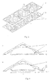
- Fig. 1 shows a perspective view of several inventive second chamber halves 12 with openings 14 (intermediate) according to a preferred embodiment, which were prepared by punching from a stainless steel sheet and are connected by narrow webs 15 with the punch frame 16.
- the halves 12 are flat and round and have a thickness of 0.3 mm and an outer diameter of 30 mm.
- the opening 14 is square with a side length of 6 mm. In other preferred embodiments, the thickness and diameter of the second half 12 are typically in the range of 0.2-0.6 mm and 10-50 mm, respectively.
- the shape of the opening 14 can be chosen arbitrarily and z. B. adapted to the shape of a valve to be fitted.
- the opening 14 may be rectangular, triangular, oval or circular, with diameters typically in the range of 1-15 mm.
- Fig. 2 shows a perspective view of a plurality of first chamber halves 10 (intermediate) according to the same preferred embodiment as in Fig. 1 shown.
- the first halves 10 were also made by punching from a stainless steel sheet, are connected by narrow webs 15 with the punching frame 18 and like the second halves 12 are flat and round formed with a thickness of 0.1 mm (typical range 0.05-2 mm) and a diameter of 30 mm (typical range 10-50 mm). While the first 10 and second halves 12 in the present embodiment have identical diameters, in other preferred embodiments, the diameters of the two halves 10, 12 may also be selected to be different from each other. For example, the diameter of the first half 10 may be greater than that of the second half 12. As in Fig.
- the two punching frames 16, 18 are simply superposed on each other, whereby at least in each case a contained in frame 16 first half 10 and a frame 18 contained in the second half 12 are exactly above each other.
- the punching frames 16, 18 can also be designed as endless belts, which facilitates the automation of the machining processes.
- Fig. 4A shows a cross-sectional view of a congruently laid over a second chamber half 12 first chamber half 10 before the connecting step.
- the two superimposed halves 10, 12 are laser welded together from the side of the first half 10.
- this joining step can also take place from the side of the second half. Since the connected halves 10, 12 are removed from the frames 16, 18 only after the deformation step of the second half 12, that is, when the chamber forming process is completed, automation of the manufacturing process is facilitated.
- Fig. 4B shows a cross-sectional view of the interconnected by laser welding in Fig. 4A shown first 10 and second chamber half 12 (intermediate).
- a CW fiber laser with a wavelength of 1064 nm (typical range 800-1200 nm), a power of 100 W (typical range 50-200 W) and a focused laser spot diameter of 30 ⁇ m (typical range 20- 40 ⁇ m), although other lasers are also suitable for metalworking.
- the lateral jet velocity during the Welding process was 300 mm / sec (typical range 200-600 mm / sec).
- the laser weld 20 is circular in shape and has a diameter of 28 mm (typical range 10-50 mm, depending on the dimensions of the two chamber halves 10, 12). How out Fig. 4B It can be seen, there is already in the welding process to a first deformation (and thus curvature) of the two chamber halves 10, 12. This creates a cavity 30 between the circular chamber halves 10, 12. The curvature of the clamp halves 10, 12 is simultaneously with a slight reduction 31 of the halves 10, 12 connected in the radial direction (shrinking). Since the webs 15 are formed narrow and flexible, the deformations of the chamber halves 10, 12 have no influence on the punching frames 16, 18, so that they retain their original shape.
- the webs serve as a suspension for the chamber halves in the punching frame 16,18.
- the "decoupling" of the deformation of the chamber halves 10, 12 from the frames 16, 18 by the narrow and flexible webs 15 enables the halves 10, 12 to be reliably deformed without interference from the frames 16, 18. Otherwise, as the halves deform, the frames may deform and stiffen.
- FIG. 5 shows a cross-sectional view of the interconnected first 10 and second chamber halves 12 after deformation of the second chamber half 12 according to the present embodiment.
- the same laser was used as for the welding step with the configuration described above (in further embodiments, the parameters of the laser in the areas described above vary).
- Laser beam forming was carried out at a lateral jet velocity of 600 mm / sec (typical range 100-800 mm / sec) and with a focused laser spot with a diameter of 50 ⁇ m (typical range 40-80 ⁇ m).
- a lateral jet velocity typically range 100-800 mm / sec
- a focused laser spot typically range 40-80 ⁇ m.
- the second chamber half 12 has a closed circular deformation seam 22 and a plurality of open, radially arranged and rectilinear deformation seams 22 of different lengths.
- any number of deformation seams 22 of any shape can be selected, wherein a curvature of the second chamber half 12 can also be achieved by a single seam 22.
- the diameters (or generally lateral dimensions) of closed deformation seams 22 are typically in the range of 15-50 mm depending, inter alia, on the dimensions of the chamber halves 10, 12. In the present, in Fig.
- Fig. 6a and b show plan views of integrated in stamping frames 16, 18 chambers of different embodiments, wherein the in Fig. 6a illustrated configuration of the in the Fig. 4B and 5 shown corresponds.
- Fig. 6b shown embodiment in which the two chambers are in fluid communication with each other via a narrow connection is in particular for use in pumps, preferably in micropumps, advantageous.
- Other chamber geometries are conceivable.
- the chamber may be provided with a valve, not shown, which is in fluid communication with the opening 14.
- the valve can z. B. in or at the opening 14, or via a conduit (eg hose) are connected to this.
- the valve used here can be a check valve, z. B. of Si, metal or plastic.
- the valve may be in or at the opening 14 z. B. be attached by gluing or clamping and sealing.
- a piezoelectric element may be attached to the outer surface of the first half 10 of the chamber.
- the piezoelectric element may in this case be formed in different shapes, for. B. as a disc or ring, and be connected in different ways with the chamber, for. B. by gluing.
- An embodiment of the piezoelectric element as a ring is particularly advantageous if both chamber halves 10, 12 are provided with openings 14, z. B. when using the chamber as a filter, or in general, when an opening 14 is provided on the provided with the piezoelectric element half 10, 12, for. B. when using the chamber for generating aerosols (see Fig. 10a ).
- the piezoring can be arranged around one of the openings 14, so that unimpeded liquid intake or discharge through the respective opening 14 is possible.
- the arrangement of the piezoelectric element relative to the weld 20 can be chosen differently, for.
- the weld 20 may be within a piezoring, depending on the configuration of the chamber.
- Fig. 7a shows a cross-sectional view of a micropump according to a first embodiment of the invention.
- the micropump comprises a pump chamber made of sheet steel with a first chamber half 10 and a second chamber half 12 of the in the Fig. 1 to 6 a shown embodiment.
- the thicknesses (thicknesses) of the chamber halves 10, 12, as well as the dimensions of the other components are in Figure 7 , shown out of proportion.
- a disc-shaped piezoelectric element 48 is arranged, which is connected via a not-shown electrical connection to a voltage source and is used bipolar in the present embodiment.
- a double valve 52 is provided which includes a first 56 and a second blade member 54.
- These two blade elements are arranged as they function as check valves in each of the inlet 44 and the outlet channel 46, respectively.
- the valve is closed.
- the first blade element 56 is elastically deflectable only in the direction of the opening 14 of the chamber (whereby a fluid passage between the inlet channel 44 and the chamber opening 14 is formed by the deflection) and the second blade element 54 is elastically deflectable only in the opposite direction (FIG the deflection of a fluid passage between the chamber opening 14 and the outlet channel 46 is formed).
- a liquid or a gas, a solution
- a voltage of a certain polarity is applied to the piezo element 48 and the double valve 52 is closed.
- the voltage is reversed to the piezoelectric element 48 by the voltage source, not shown, whereby the first chamber half 10 in the direction of the second chamber half 12 is deflected (see Fig. 7b ).
- the volume of the formed between the two chamber halves 10, 12 cavity 30 is reduced and there is an overpressure in the pump chamber.
- This over-pressure causes the second blade member 54 to deflect toward the outlet port 46 and transport the liquid (or gas, solution) contained within the chamber out of the cavity 30 through the outlet port 46. If, as in Fig. 7c shown, the first chamber half 10 is fully deflected, no fluid is contained in the chamber.
- the pressure exerted by the first half 10 drops to 0 and the second blade member 54 returns to its original position, so that the double valve 52 is closed. If the polarity of the voltage applied to the piezoelectric element 48 is reversed again, the first chamber half 10 returns to its initial position, as in FIG Fig. 7d shown, which increases the volume of the cavity 30 and creates a negative pressure in the chamber. By this negative pressure, the first sheet member 56 is deflected toward the chamber opening 14 and liquid (or gas, solution) is transported through the inlet opening 44 into the chamber 30. By periodically reversing the voltage applied to the piezoelectric element 48, liquid (or gas, solution) is thus continuously transported from the inlet channel 44 into the cavity 30 and out of the cavity 30 into the outlet channel 46, ie the pump is in the conveying mode.
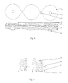
- Fig. 8 shows a bottom view of a three-part chamber according to the invention (above) and a cross-sectional view of a micropump according to a second embodiment, which uses the three-part chamber as the pumping chamber (below).
- the chamber comprises a first 50 and a second half 52, each having three round segments and as explained above and based on the Fig. 1 to 6 described interconnected and thermally deformed.
- the two outer edge segments of the second half 52 each have one Opening 54, which is for the use of the chamber as a pump chamber in the in Fig. 8 (below) is provided with a valve seat 56.
- an independently controllable actuator 53 eg a piezoelement
- the respective segment of the first half 50 can be brought into contact with the corresponding valve seat 56 such that no fluid intake or delivery via the respective opening 54 is possible (ie the valve is closed).
- This contact can be released by reversely actuating the corresponding actuator 53 (eg, by reversing the applied voltage when using a piezo element as the actuator 53), thereby opening the valve.
- the two edge segments of the chamber are in fluid communication with the central segment via short channels 58.
- the pump described above is only one field of use for the chamber (s) of the invention.
- Other uses have already been mentioned above, such as use as a filter chamber, sensor chamber or for the production of aerosols.
- Fig. 9a and b show basic sketches to explain the function of an oscillating membrane for generating aerosols.
- One or more similar apertures 64 of small exit diameter are provided in a chamber wall 62 and are in contact with a liquid 74 contained in the chamber.
- the chamber exterior is open to the atmosphere.
- the fluid 74 is subjected to pressure fluctuations, which are generated by rapid oscillations of a chamber wall.
- the pressure fluctuations drive the liquid 74 through the openings 64 in the form of small droplets, whereby an aerosol is formed on the atmosphere side.
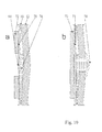
- Fig. 10a and b show cross-sectional views of chambers of different embodiments for generating aerosols.
- one or more small openings 64 in the first chamber half 10 are provided.
- An actuator 70 for generating pressure oscillations is realized by a bimorph combination of the first chamber half 10 with a piezoelectric ring 72.
- the actuator 70 is excited with an alternating voltage in the ultrasonic frequency range (typical frequencies 40 to 200 kHz), preferably in the vicinity of a mechanical resonance of the chamber.
- the chamber is at least partly with a liquid 74 filled, so that the openings 64 are wetted at least with the liquid 74.
- the small openings 64 can also be mounted in the second chamber half 12, which is optionally provided with a thin wall segment 78 ( Fig. 10b ).
- the actuator 71 may be either as in Fig. 10a shown actuator 70 may be constructed or the piezoelectric ring 72 may, for. B. be replaced by a piezoelectric disc 73, since in such an embodiment, no opening of the piezoelectric element is necessary.
Landscapes
- Engineering & Computer Science (AREA)
- Mechanical Engineering (AREA)
- General Engineering & Computer Science (AREA)
- Reciprocating Pumps (AREA)
- Shaping Metal By Deep-Drawing, Or The Like (AREA)
- Lining Or Joining Of Plastics Or The Like (AREA)
- External Artificial Organs (AREA)
Applications Claiming Priority (1)
| Application Number | Priority Date | Filing Date | Title |
|---|---|---|---|
| DE102007061920A DE102007061920A1 (de) | 2007-12-21 | 2007-12-21 | Kammer, Pumpe mit Kammer und Verfahren zur Herstellung von Kammern |
Publications (2)
| Publication Number | Publication Date |
|---|---|
| EP2072819A1 true EP2072819A1 (fr) | 2009-06-24 |
| EP2072819B1 EP2072819B1 (fr) | 2011-02-09 |
Family
ID=40469974
Family Applications (1)
| Application Number | Title | Priority Date | Filing Date |
|---|---|---|---|
| EP08172351A Not-in-force EP2072819B1 (fr) | 2007-12-21 | 2008-12-19 | Chambre de pompe et procédé de fabrication de cette chambre |
Country Status (5)
| Country | Link |
|---|---|
| US (1) | US8226380B2 (fr) |
| EP (1) | EP2072819B1 (fr) |
| AT (1) | ATE498070T1 (fr) |
| DE (2) | DE102007061920A1 (fr) |
| ES (1) | ES2363745T3 (fr) |
Cited By (1)
| Publication number | Priority date | Publication date | Assignee | Title |
|---|---|---|---|---|
| DE102018203728A1 (de) | 2018-03-13 | 2019-09-19 | Audi Ag | Verfahren zur Erzeugung einer Springbeule in einem Blechteil |
Families Citing this family (2)
| Publication number | Priority date | Publication date | Assignee | Title |
|---|---|---|---|---|
| CN102884352B (zh) * | 2010-03-05 | 2014-06-18 | 弗兰霍菲尔运输应用研究公司 | 弯曲换能器、微型泵和微型阀的制造方法以及微型泵和微型阀 |
| WO2021106301A1 (fr) * | 2019-11-28 | 2021-06-03 | 株式会社村田製作所 | Actionneur et dispositif de régulation de fluide |
Citations (7)
| Publication number | Priority date | Publication date | Assignee | Title |
|---|---|---|---|---|
| US3606592A (en) | 1970-05-20 | 1971-09-20 | Bendix Corp | Fluid pump |
| EP0025005A1 (fr) | 1979-08-18 | 1981-03-11 | Schaldach, Max, Prof. Dr. Ing. | Dispositif pour débiter et doser des quantités minimes de liquide |
| DE4140533A1 (de) * | 1991-12-09 | 1993-06-17 | Joseph Voegele Ag | Verfahren und vorrichtung zum mikrodosieren von schmierstoff |
| DE19720482A1 (de) | 1997-05-16 | 1998-11-19 | Inst Mikrotechnik Mainz Gmbh | Mikromembranpumpe |
| WO2002028532A2 (fr) * | 2000-10-06 | 2002-04-11 | Protasis Corporation | Ensemble substrat a microfluide et procede de realisation de ce dernier |
| DE10238585B3 (de) | 2002-08-22 | 2004-04-22 | Fraunhofer-Gesellschaft zur Förderung der angewandten Forschung e.V. | Zweiteiliges Fluidmodul |
| WO2004081390A1 (fr) * | 2003-03-11 | 2004-09-23 | Fraunhofer-Gesellschaft zur Förderung der angewandten Forschung e. V. | Microvanne normalement doublement fermee |
Family Cites Families (4)
| Publication number | Priority date | Publication date | Assignee | Title |
|---|---|---|---|---|
| DE3320443C2 (de) * | 1983-06-06 | 1994-08-18 | Siemens Ag | Flüssigkeitspumpe |
| US5632841A (en) | 1995-04-04 | 1997-05-27 | The United States Of America As Represented By The Administrator Of The National Aeronautics And Space Administration | Thin layer composite unimorph ferroelectric driver and sensor |
| US20060232167A1 (en) * | 2005-04-13 | 2006-10-19 | Par Technologies Llc | Piezoelectric diaphragm with aperture(s) |
| US20060245949A1 (en) * | 2005-04-13 | 2006-11-02 | Par Technologies, Llc | Electromagnetically bonded pumps and pump subassemblies and methods of fabrication |
-
2007
- 2007-12-21 DE DE102007061920A patent/DE102007061920A1/de not_active Withdrawn
-
2008
- 2008-12-19 AT AT08172351T patent/ATE498070T1/de active
- 2008-12-19 DE DE502008002552T patent/DE502008002552D1/de active Active
- 2008-12-19 ES ES08172351T patent/ES2363745T3/es active Active
- 2008-12-19 EP EP08172351A patent/EP2072819B1/fr not_active Not-in-force
- 2008-12-19 US US12/339,432 patent/US8226380B2/en not_active Expired - Fee Related
Patent Citations (7)
| Publication number | Priority date | Publication date | Assignee | Title |
|---|---|---|---|---|
| US3606592A (en) | 1970-05-20 | 1971-09-20 | Bendix Corp | Fluid pump |
| EP0025005A1 (fr) | 1979-08-18 | 1981-03-11 | Schaldach, Max, Prof. Dr. Ing. | Dispositif pour débiter et doser des quantités minimes de liquide |
| DE4140533A1 (de) * | 1991-12-09 | 1993-06-17 | Joseph Voegele Ag | Verfahren und vorrichtung zum mikrodosieren von schmierstoff |
| DE19720482A1 (de) | 1997-05-16 | 1998-11-19 | Inst Mikrotechnik Mainz Gmbh | Mikromembranpumpe |
| WO2002028532A2 (fr) * | 2000-10-06 | 2002-04-11 | Protasis Corporation | Ensemble substrat a microfluide et procede de realisation de ce dernier |
| DE10238585B3 (de) | 2002-08-22 | 2004-04-22 | Fraunhofer-Gesellschaft zur Förderung der angewandten Forschung e.V. | Zweiteiliges Fluidmodul |
| WO2004081390A1 (fr) * | 2003-03-11 | 2004-09-23 | Fraunhofer-Gesellschaft zur Förderung der angewandten Forschung e. V. | Microvanne normalement doublement fermee |
Cited By (1)
| Publication number | Priority date | Publication date | Assignee | Title |
|---|---|---|---|---|
| DE102018203728A1 (de) | 2018-03-13 | 2019-09-19 | Audi Ag | Verfahren zur Erzeugung einer Springbeule in einem Blechteil |
Also Published As
| Publication number | Publication date |
|---|---|
| EP2072819B1 (fr) | 2011-02-09 |
| DE102007061920A1 (de) | 2009-06-25 |
| ES2363745T3 (es) | 2011-08-12 |
| US8226380B2 (en) | 2012-07-24 |
| ATE498070T1 (de) | 2011-02-15 |
| US20090158923A1 (en) | 2009-06-25 |
| DE502008002552D1 (de) | 2011-03-24 |
Similar Documents
| Publication | Publication Date | Title |
|---|---|---|
| EP2389529B1 (fr) | Soupape, en particulier pour un composant de la technique des microfluides | |
| EP2118542B1 (fr) | Microsoupape | |
| DE4402119C2 (de) | Verfahren zur Herstellung von Mikromembranpumpen | |
| DE4332720C2 (de) | Mikromembranpumpe | |
| EP2207963B1 (fr) | Pompe et ensemble pompe | |
| EP2962758B1 (fr) | Cellule d'écoulement dotée d'une zone de stockage et d'un canal de transport pouvant s'ouvrir à un point de rupture | |
| DE102011003856B4 (de) | Mikrosystem für fluidische Anwendungen sowie Herstellungsverfahren und Benutzungsverfahren für ein Mikrosystem für fluidische Anwendungen | |
| EP2611594B1 (fr) | Procedé de fabrication d'un dispositif microfluidique et appareil de laminage qui y sont associés | |
| DE10293217T5 (de) | Dichtung aus Polymer/Metall-Laminat-Konstruktionen | |
| EP2531760A1 (fr) | Elément structural microfluidique conçu pour la manipulation d'un fluide et puce microfluidique | |
| DE112018005660B4 (de) | Pumpe und fluidsteuerungsvorrichtung | |
| EP3884527B1 (fr) | Dispositif de transport comprenant un actionneur et une couche de séparation | |
| EP3382238B1 (fr) | Membrane et son procédé de fabrication | |
| EP2072819B1 (fr) | Chambre de pompe et procédé de fabrication de cette chambre | |
| DE69313766T2 (de) | Mikrosteuervorrichtung fuer fluidum und verfahren zu deren herstellung | |
| WO2017178208A1 (fr) | Élément de soupape à puce rfid | |
| WO2010031559A1 (fr) | Vanne microfluidique, pompe microfluidique, système microfluidique et procédé de production | |
| DE19844518A1 (de) | Hydraulischer Wegverstärker für Mikrosysteme | |
| DE102015207964A1 (de) | Verfahren zur Herstellung einer Bipolarplatte und Fertigungsvorrichtung | |
| WO2010058029A1 (fr) | Mécanisme d'entraînement pour le déplacement d'un objet sur un axe de déplacement et microvanne | |
| EP3236081B1 (fr) | Aube de ventilateur centrifuge fabriquée en tôle pliée avec un joint sur l'extrados ou sur l'intrados | |
| WO2001094234A1 (fr) | Conteneur a parois minces et son procede de fabrication | |
| EP1525378B1 (fr) | Couche metallique a parties presentant des epaisseurs de materiau differentes, son procede de production et corps en nid d'abeille produits au moins partiellement a partir desdites couches metalliques | |
| EP2024704A1 (fr) | Dispositif échangeur de chaleur | |
| EP2522427A1 (fr) | Dispositif microfluidique et son procédé de fabrication |
Legal Events
| Date | Code | Title | Description |
|---|---|---|---|
| PUAI | Public reference made under article 153(3) epc to a published international application that has entered the european phase |
Free format text: ORIGINAL CODE: 0009012 |
|
| AK | Designated contracting states |
Kind code of ref document: A1 Designated state(s): AT BE BG CH CY CZ DE DK EE ES FI FR GB GR HR HU IE IS IT LI LT LU LV MC MT NL NO PL PT RO SE SI SK TR |
|
| AX | Request for extension of the european patent |
Extension state: AL BA MK RS |
|
| 17P | Request for examination filed |
Effective date: 20091221 |
|
| AKX | Designation fees paid |
Designated state(s): AT BE BG CH CY CZ DE DK EE ES FI FR GB GR HR HU IE IS IT LI LT LU LV MC MT NL NO PL PT RO SE SI SK TR |
|
| GRAP | Despatch of communication of intention to grant a patent |
Free format text: ORIGINAL CODE: EPIDOSNIGR1 |
|
| GRAS | Grant fee paid |
Free format text: ORIGINAL CODE: EPIDOSNIGR3 |
|
| GRAA | (expected) grant |
Free format text: ORIGINAL CODE: 0009210 |
|
| AK | Designated contracting states |
Kind code of ref document: B1 Designated state(s): AT BE BG CH CY CZ DE DK EE ES FI FR GB GR HR HU IE IS IT LI LT LU LV MC MT NL NO PL PT RO SE SI SK TR |
|
| REG | Reference to a national code |
Ref country code: GB Ref legal event code: FG4D Free format text: NOT ENGLISH |
|
| REG | Reference to a national code |
Ref country code: CH Ref legal event code: EP |
|
| REG | Reference to a national code |
Ref country code: IE Ref legal event code: FG4D Free format text: LANGUAGE OF EP DOCUMENT: GERMAN |
|
| REF | Corresponds to: |
Ref document number: 502008002552 Country of ref document: DE Date of ref document: 20110324 Kind code of ref document: P |
|
| REG | Reference to a national code |
Ref country code: DE Ref legal event code: R096 Ref document number: 502008002552 Country of ref document: DE Effective date: 20110324 |
|
| REG | Reference to a national code |
Ref country code: NL Ref legal event code: VDEP Effective date: 20110209 |
|
| LTIE | Lt: invalidation of european patent or patent extension |
Effective date: 20110209 |
|
| PG25 | Lapsed in a contracting state [announced via postgrant information from national office to epo] |
Ref country code: HR Free format text: LAPSE BECAUSE OF FAILURE TO SUBMIT A TRANSLATION OF THE DESCRIPTION OR TO PAY THE FEE WITHIN THE PRESCRIBED TIME-LIMIT Effective date: 20110209 Ref country code: LV Free format text: LAPSE BECAUSE OF FAILURE TO SUBMIT A TRANSLATION OF THE DESCRIPTION OR TO PAY THE FEE WITHIN THE PRESCRIBED TIME-LIMIT Effective date: 20110209 Ref country code: GR Free format text: LAPSE BECAUSE OF FAILURE TO SUBMIT A TRANSLATION OF THE DESCRIPTION OR TO PAY THE FEE WITHIN THE PRESCRIBED TIME-LIMIT Effective date: 20110510 Ref country code: SE Free format text: LAPSE BECAUSE OF FAILURE TO SUBMIT A TRANSLATION OF THE DESCRIPTION OR TO PAY THE FEE WITHIN THE PRESCRIBED TIME-LIMIT Effective date: 20110209 Ref country code: NO Free format text: LAPSE BECAUSE OF FAILURE TO SUBMIT A TRANSLATION OF THE DESCRIPTION OR TO PAY THE FEE WITHIN THE PRESCRIBED TIME-LIMIT Effective date: 20110509 Ref country code: LT Free format text: LAPSE BECAUSE OF FAILURE TO SUBMIT A TRANSLATION OF THE DESCRIPTION OR TO PAY THE FEE WITHIN THE PRESCRIBED TIME-LIMIT Effective date: 20110209 Ref country code: PT Free format text: LAPSE BECAUSE OF FAILURE TO SUBMIT A TRANSLATION OF THE DESCRIPTION OR TO PAY THE FEE WITHIN THE PRESCRIBED TIME-LIMIT Effective date: 20110609 |
|
| REG | Reference to a national code |
Ref country code: ES Ref legal event code: FG2A Ref document number: 2363745 Country of ref document: ES Kind code of ref document: T3 Effective date: 20110812 |
|
| PG25 | Lapsed in a contracting state [announced via postgrant information from national office to epo] |
Ref country code: SI Free format text: LAPSE BECAUSE OF FAILURE TO SUBMIT A TRANSLATION OF THE DESCRIPTION OR TO PAY THE FEE WITHIN THE PRESCRIBED TIME-LIMIT Effective date: 20110209 Ref country code: FI Free format text: LAPSE BECAUSE OF FAILURE TO SUBMIT A TRANSLATION OF THE DESCRIPTION OR TO PAY THE FEE WITHIN THE PRESCRIBED TIME-LIMIT Effective date: 20110209 Ref country code: BG Free format text: LAPSE BECAUSE OF FAILURE TO SUBMIT A TRANSLATION OF THE DESCRIPTION OR TO PAY THE FEE WITHIN THE PRESCRIBED TIME-LIMIT Effective date: 20110509 Ref country code: CY Free format text: LAPSE BECAUSE OF FAILURE TO SUBMIT A TRANSLATION OF THE DESCRIPTION OR TO PAY THE FEE WITHIN THE PRESCRIBED TIME-LIMIT Effective date: 20110209 Ref country code: NL Free format text: LAPSE BECAUSE OF FAILURE TO SUBMIT A TRANSLATION OF THE DESCRIPTION OR TO PAY THE FEE WITHIN THE PRESCRIBED TIME-LIMIT Effective date: 20110209 Ref country code: PL Free format text: LAPSE BECAUSE OF FAILURE TO SUBMIT A TRANSLATION OF THE DESCRIPTION OR TO PAY THE FEE WITHIN THE PRESCRIBED TIME-LIMIT Effective date: 20110209 |
|
| REG | Reference to a national code |
Ref country code: IE Ref legal event code: FD4D |
|
| PG25 | Lapsed in a contracting state [announced via postgrant information from national office to epo] |
Ref country code: EE Free format text: LAPSE BECAUSE OF FAILURE TO SUBMIT A TRANSLATION OF THE DESCRIPTION OR TO PAY THE FEE WITHIN THE PRESCRIBED TIME-LIMIT Effective date: 20110209 Ref country code: DK Free format text: LAPSE BECAUSE OF FAILURE TO SUBMIT A TRANSLATION OF THE DESCRIPTION OR TO PAY THE FEE WITHIN THE PRESCRIBED TIME-LIMIT Effective date: 20110209 Ref country code: IE Free format text: LAPSE BECAUSE OF FAILURE TO SUBMIT A TRANSLATION OF THE DESCRIPTION OR TO PAY THE FEE WITHIN THE PRESCRIBED TIME-LIMIT Effective date: 20110209 |
|
| PG25 | Lapsed in a contracting state [announced via postgrant information from national office to epo] |
Ref country code: CZ Free format text: LAPSE BECAUSE OF FAILURE TO SUBMIT A TRANSLATION OF THE DESCRIPTION OR TO PAY THE FEE WITHIN THE PRESCRIBED TIME-LIMIT Effective date: 20110209 Ref country code: SK Free format text: LAPSE BECAUSE OF FAILURE TO SUBMIT A TRANSLATION OF THE DESCRIPTION OR TO PAY THE FEE WITHIN THE PRESCRIBED TIME-LIMIT Effective date: 20110209 Ref country code: RO Free format text: LAPSE BECAUSE OF FAILURE TO SUBMIT A TRANSLATION OF THE DESCRIPTION OR TO PAY THE FEE WITHIN THE PRESCRIBED TIME-LIMIT Effective date: 20110209 |
|
| PLBE | No opposition filed within time limit |
Free format text: ORIGINAL CODE: 0009261 |
|
| STAA | Information on the status of an ep patent application or granted ep patent |
Free format text: STATUS: NO OPPOSITION FILED WITHIN TIME LIMIT |
|
| 26N | No opposition filed |
Effective date: 20111110 |
|
| REG | Reference to a national code |
Ref country code: DE Ref legal event code: R097 Ref document number: 502008002552 Country of ref document: DE Effective date: 20111110 |
|
| BERE | Be: lapsed |
Owner name: PARITEC G.M.B.H. Effective date: 20111231 |
|
| PG25 | Lapsed in a contracting state [announced via postgrant information from national office to epo] |
Ref country code: MC Free format text: LAPSE BECAUSE OF NON-PAYMENT OF DUE FEES Effective date: 20111231 |
|
| PG25 | Lapsed in a contracting state [announced via postgrant information from national office to epo] |
Ref country code: BE Free format text: LAPSE BECAUSE OF NON-PAYMENT OF DUE FEES Effective date: 20111231 |
|
| PG25 | Lapsed in a contracting state [announced via postgrant information from national office to epo] |
Ref country code: MT Free format text: LAPSE BECAUSE OF FAILURE TO SUBMIT A TRANSLATION OF THE DESCRIPTION OR TO PAY THE FEE WITHIN THE PRESCRIBED TIME-LIMIT Effective date: 20110209 |
|
| PG25 | Lapsed in a contracting state [announced via postgrant information from national office to epo] |
Ref country code: LU Free format text: LAPSE BECAUSE OF NON-PAYMENT OF DUE FEES Effective date: 20111219 |
|
| PG25 | Lapsed in a contracting state [announced via postgrant information from national office to epo] |
Ref country code: IS Free format text: LAPSE BECAUSE OF FAILURE TO SUBMIT A TRANSLATION OF THE DESCRIPTION OR TO PAY THE FEE WITHIN THE PRESCRIBED TIME-LIMIT Effective date: 20110209 |
|
| REG | Reference to a national code |
Ref country code: CH Ref legal event code: PL |
|
| PG25 | Lapsed in a contracting state [announced via postgrant information from national office to epo] |
Ref country code: TR Free format text: LAPSE BECAUSE OF FAILURE TO SUBMIT A TRANSLATION OF THE DESCRIPTION OR TO PAY THE FEE WITHIN THE PRESCRIBED TIME-LIMIT Effective date: 20110209 |
|
| PG25 | Lapsed in a contracting state [announced via postgrant information from national office to epo] |
Ref country code: HU Free format text: LAPSE BECAUSE OF FAILURE TO SUBMIT A TRANSLATION OF THE DESCRIPTION OR TO PAY THE FEE WITHIN THE PRESCRIBED TIME-LIMIT Effective date: 20110209 Ref country code: LI Free format text: LAPSE BECAUSE OF NON-PAYMENT OF DUE FEES Effective date: 20121231 Ref country code: CH Free format text: LAPSE BECAUSE OF NON-PAYMENT OF DUE FEES Effective date: 20121231 |
|
| PGFP | Annual fee paid to national office [announced via postgrant information from national office to epo] |
Ref country code: GB Payment date: 20131217 Year of fee payment: 6 |
|
| PGFP | Annual fee paid to national office [announced via postgrant information from national office to epo] |
Ref country code: IT Payment date: 20131218 Year of fee payment: 6 Ref country code: FR Payment date: 20131213 Year of fee payment: 6 Ref country code: ES Payment date: 20131216 Year of fee payment: 6 |
|
| PGFP | Annual fee paid to national office [announced via postgrant information from national office to epo] |
Ref country code: DE Payment date: 20131217 Year of fee payment: 6 |
|
| REG | Reference to a national code |
Ref country code: AT Ref legal event code: MM01 Ref document number: 498070 Country of ref document: AT Kind code of ref document: T Effective date: 20131219 |
|
| PG25 | Lapsed in a contracting state [announced via postgrant information from national office to epo] |
Ref country code: AT Free format text: LAPSE BECAUSE OF NON-PAYMENT OF DUE FEES Effective date: 20131219 |
|
| REG | Reference to a national code |
Ref country code: DE Ref legal event code: R119 Ref document number: 502008002552 Country of ref document: DE |
|
| GBPC | Gb: european patent ceased through non-payment of renewal fee |
Effective date: 20141219 |
|
| REG | Reference to a national code |
Ref country code: FR Ref legal event code: ST Effective date: 20150831 |
|
| PG25 | Lapsed in a contracting state [announced via postgrant information from national office to epo] |
Ref country code: DE Free format text: LAPSE BECAUSE OF NON-PAYMENT OF DUE FEES Effective date: 20150701 Ref country code: GB Free format text: LAPSE BECAUSE OF NON-PAYMENT OF DUE FEES Effective date: 20141219 |
|
| PG25 | Lapsed in a contracting state [announced via postgrant information from national office to epo] |
Ref country code: FR Free format text: LAPSE BECAUSE OF NON-PAYMENT OF DUE FEES Effective date: 20141231 |
|
| PG25 | Lapsed in a contracting state [announced via postgrant information from national office to epo] |
Ref country code: IT Free format text: LAPSE BECAUSE OF NON-PAYMENT OF DUE FEES Effective date: 20141219 |
|
| REG | Reference to a national code |
Ref country code: ES Ref legal event code: FD2A Effective date: 20160127 |
|
| PG25 | Lapsed in a contracting state [announced via postgrant information from national office to epo] |
Ref country code: ES Free format text: LAPSE BECAUSE OF NON-PAYMENT OF DUE FEES Effective date: 20141220 |