EP0025438B1 - Axial piston pump - Google Patents
Axial piston pump Download PDFInfo
- Publication number
- EP0025438B1 EP0025438B1 EP80900429A EP80900429A EP0025438B1 EP 0025438 B1 EP0025438 B1 EP 0025438B1 EP 80900429 A EP80900429 A EP 80900429A EP 80900429 A EP80900429 A EP 80900429A EP 0025438 B1 EP0025438 B1 EP 0025438B1
- Authority
- EP
- European Patent Office
- Prior art keywords
- pump
- port
- distribution plate
- plate
- cylinder block
- Prior art date
- Legal status (The legal status is an assumption and is not a legal conclusion. Google has not performed a legal analysis and makes no representation as to the accuracy of the status listed.)
- Expired
Links
- 239000012530 fluid Substances 0.000 claims abstract description 31
- 238000010992 reflux Methods 0.000 claims abstract description 26
- 238000005086 pumping Methods 0.000 claims abstract description 16
- 230000007935 neutral effect Effects 0.000 claims abstract description 10
- 230000007246 mechanism Effects 0.000 claims description 3
- 230000004941 influx Effects 0.000 claims 1
- 238000012423 maintenance Methods 0.000 claims 1
- 238000006073 displacement reaction Methods 0.000 description 6
- 239000003921 oil Substances 0.000 description 4
- 230000001419 dependent effect Effects 0.000 description 1
- 230000000694 effects Effects 0.000 description 1
- 238000001914 filtration Methods 0.000 description 1
- 230000020169 heat generation Effects 0.000 description 1
- 239000010720 hydraulic oil Substances 0.000 description 1
- 230000006872 improvement Effects 0.000 description 1
- 230000003993 interaction Effects 0.000 description 1
- 230000001095 motoneuron effect Effects 0.000 description 1
- 230000002277 temperature effect Effects 0.000 description 1
Images


Classifications
-
- F—MECHANICAL ENGINEERING; LIGHTING; HEATING; WEAPONS; BLASTING
- F04—POSITIVE - DISPLACEMENT MACHINES FOR LIQUIDS; PUMPS FOR LIQUIDS OR ELASTIC FLUIDS
- F04B—POSITIVE-DISPLACEMENT MACHINES FOR LIQUIDS; PUMPS
- F04B1/00—Multi-cylinder machines or pumps characterised by number or arrangement of cylinders
- F04B1/12—Multi-cylinder machines or pumps characterised by number or arrangement of cylinders having cylinder axes coaxial with, or parallel or inclined to, main shaft axis
- F04B1/20—Multi-cylinder machines or pumps characterised by number or arrangement of cylinders having cylinder axes coaxial with, or parallel or inclined to, main shaft axis having rotary cylinder block
- F04B1/2014—Details or component parts
- F04B1/2042—Valves
Definitions
- the present invention relates to an axial piston pump of the kind defined in the precharacterizing part of claim 1.
- Pumps are also known having a variable displacement.
- One such pump is disclosed in DE-A-25 01 867.
- the fluid in the known pump is controlled by means of the distribution plate and a slide arrangement which means that the reflux to the pump is restricted.
- Another known axial piston-type pump comprises a rotatable cylinder bloc, tiltable in only one direction; a distribution plate provided with an inlet slot and an outlet slot and a stationary port plate provided with an outlet port and one inlet reflux port.
- the inlet- reflux port permits the used pressure fluid to return to the pump housing and to the pump intake opening.
- One main object of the present invention is to provide a new type of axial piston pump in which the disadvantageous effects described above are eliminated, which is accomplished as described in the characterizing portion of claim 1.
- the pump shown in Figure 1 comprises a housing 10 represented diagrammatically and enclosing a rotatably mounted drive shaft 12 with drive shaft flange 14, which drive shaft is actuated by a drive motor not shown here.
- Pivotably mounted in the housing is a cylinder barrel or block 16 containing at least one cylinder 18 within which a piston 20 is received for reciprocating movement.
- the pistons 20 are mounted in usual manner in the drive shaft flange 14 e.g. by means of ball-formed bearings so that the cylinder block rotates with the drive shaft flange.
- the cylinder block 16 can be tilted relatively to the drive shaft flange 14 whereby the pistons on rotation of the cylinder block 16 are imparted a reciprocating movement within the cylinders, the stroke of which movement becomes dependent on the angle between the drive shaft 12 and the cylinder block 16.
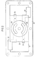
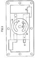
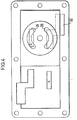
- a valve or distribution plate 22 Disposed overhead of the cylinder block is a valve or distribution plate 22 which is formed with slots 24, 26 ( Figures 2-4), the pistons moving in outward direction through one of the slots 24, 26 becoming connected with an intake or suction port in the housing and the pistons which are on their way into the bores through the other slot 24, 26 being in communication with an exhaust or pressure port in the pump housing 10.
- the exhaust or pressure port and the reflux port are denoted A or B in the figures.
- the described pump according to the invention has variable or adjustable displacement, i.e. the angle between the drive shaft flange and the cylinder block can be varied to an inclination from 0 to about 25 degrees in both directions from the neutral position shown in Figure 1 where the angle is 0.
- the angle is thus varied in the shown embodiment by a tilting displacement of the cylinder block 16 and the distribution plate 22 to the left or the right in the shown figure about the pivot point x.
- the distribution plate 22 is rotationally stationary and thus does not participate in the rotation of the cylinder block 16.
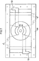
- a stationary port plate 28 in which the reflux and exhaust ports A or B are provided.
- the port plate 28 is fixed to the pump housing and thus does not participate in the angular setting of the cylinder block 16 and the distribution plate 22. From Figure 2 there is evident the positioning of the ports when the distribution plate 22 is in the neutral position of the pump with the angle 0, i.e. the position shown in Figure 1.
- the sector surface of the housing 10 at the top portion of the pump is surrounded by a flange 30 by which the port plate 28 is rigidly secured to the pump housing.
- the distribution plate 22 which extends to the tight abutment against the sector surface of the housing 10 contains, as described earlier, the valve slots 24, 26, and about these valve slots the sector surface of the cylinder block 16 is indicated in the form of a ring. Further, there are shown diagrammatically port openings 32 for feed oil to the cylinder block 16 and the ports A and B, of which in the following description the port A will be denoted reflux port and the port B exhaust port. Of course, the relation of the ports to one another will be reversed when the direction of rotation is changed, which means that the port B will become the reflux port and the port A the exhaust port. It will be easily understood from Figure 2 that no fluid, such as oil, in the neutral position is supplied to the ports A, B from the cylinders 18 in the cylinder block 16.
- the distribution plate 22 leaves both in the port A and in the port B a gap 34, the function of which will be described nearer hereinafter. From said Figure 2 it will be evident also that the feed ports 32 are extended nearer to the centre line of the cylinder block 16 and the valve slots 24, 26 than the ports A and B in order not to obtain too small an open area of the feed port 32 when the pumping operation is started, since otherwise cavitation could be caused.
- Figure 4 shows the corresponding position with the highest volume to the exhaust port B, i.e. when the cylinder block 16 has been tilted to the right as far as possible in Figure 1, usually by about 25° relative the centre line of the drive shaft flange 14.
- the shown and described axial shaft pump forms part of a system presented diagrammatically in Figure 1 and including a control cylinder 36 with piston 38.
- the pressure fluid from the pump is fed through the pipe 40 from the pump 10 to the cylinder 36 and is returned through the pipe 42 from the opposite part of the cylinder.
- Inserted into each circuit or duct 40, 42 are non-return valves 44 and overflow valves 46 which through pipes 48 are coupled to the reverse circuit to or from, respectively, the cylinder 36.
- the pre-feeding may be effected by means of, for example, a separate pump 64 from the receptacle 56.
- Slipping clutch devices are found in known pumps which devices require power even when no fluid is taken out to any operational circuit because of the circulation by pumping of the fluid.
- the cylinder block 16 and the distribution plate 22 are tilted so much only as the operation requires, which means that when an operation with little volume is desired, it is possible also with constant number of revolutions of the driving motor to achieve much softer starts, and the operations can be run for a long time at low speed without any negative temperature effects.
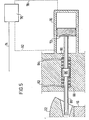
- the positive guiding may be effected by means of, for example, the servo mechanism shown in Figure 5 for controlling and centering the tilting of the pump.
- Hydraulic fluid is supplied to servo cylinder 70 with servo piston 72 through, for example, pipe 74 and a servo control device 76.
- the servo fluid may be, for example, a branch portion of the pre-feed fluid (the pipe 50) to the pump in Figure 1.
- the pump When the pressure reaches the desired highest value, the pump is returned so that the pumping is discontinued even if the servo pressure is still active in the pipe 78. The same holds true when the pressure fluid instead is supplied to the servo pipe on the front side of the piston, viz. through pipe 92.
- the piston 86 also may have different piston areas on its one and other side (not shown).
- the ports A and B are exhaust or reflux ports, depending on in what direction the cylinder block 16 and the distribution member 22 are inclined.
- the inclination movement in the one direction may be limited by means of a mechanical stopper (not shown) so as to obtain a lower maximum volume for the pump flow to the front side (with the piston rod 39) of the piston 38 which side has the smallest area. In this way the same speed is obtained for both directions of movement of the cylinder 36.
- the non-return valves 44 and overflow valves 46 in each pipe 40, 42 are preferably devised as sleeve type valves so that overflow of fluid from one side to the other results in slow opening of the non-return valve so as to prevent sudden pressure drop to occur in the reflux fluid.
- the pre-feed pressure is no absolute necessity in the system, but it renders many advantages in a system having a plurality of operative functions. As described, it can be used through the servo control device 76 to select direction and speed, in which connection also a very small risk of cavitation exists. Oil exchange and filtering are effected, as described, via throttle valve 58 and pressure limiting valve 60 and filter 63 to receptacle 56.
- Fig. 6 shows a view similar to Figure 1 of a modified embodiment and Figure 7 shows a section along line VII-VII in Figure 6, the same reference numerals being employed as before under addition of the number one hundred.
- reference sign 110 denotes the pumphousing, 114 the drive shaft flange, 116 the cylinder block 124 and 126 the slots, 128 the port plate and 130 the port plate flange.
- the exhausts A" and B" may here open on both sides of the distribution plate 122.
- the passage of each port to the associated intake duct 132 is realized as before. To equalize the pressure which in axial direction acts against the bearing, the port in this position becomes closed against the sector surface, and balance can be reached.
- the system according to the invention affords the possibility of direct reciprocity between deflection of the control rod and the speed of the operative function irrespective of the magnitude of the load.
- the port plate comprises at least one feed opening for supply of pressure fluid to the pump and that the arrangement of the exhaust and reflux channels in the stationary port plate is of such a kind that the outlet and inlet slots or apertures by outward inclination of the distribution plate from zero position are brought to gradually increasing communication with the feed opening and the exhaust channel (A or B) for the discharge of fluid from the pump, the reflux channel (B or A) for the reflux to the pump becoming opened gradually simultaneously by the distribution plate, which reflux channel is connected to the pressure fluid feed to the pump, more distinctly the pump housing 10, which serves as reservoir for the pressure fluid.
- the volume difference between the two faces of the piston 38 of the pressure fluid cylinder 36 is prevented from influencing the operative function.
Landscapes
- Engineering & Computer Science (AREA)
- Mechanical Engineering (AREA)
- General Engineering & Computer Science (AREA)
- Reciprocating Pumps (AREA)
Applications Claiming Priority (2)
| Application Number | Priority Date | Filing Date | Title |
|---|---|---|---|
| SE7901669 | 1979-02-23 | ||
| SE7901669A SE417354B (sv) | 1979-02-23 | 1979-02-23 | Axialkolvpump |
Publications (2)
| Publication Number | Publication Date |
|---|---|
| EP0025438A1 EP0025438A1 (en) | 1981-03-25 |
| EP0025438B1 true EP0025438B1 (en) | 1983-05-25 |
Family
ID=20337385
Family Applications (1)
| Application Number | Title | Priority Date | Filing Date |
|---|---|---|---|
| EP80900429A Expired EP0025438B1 (en) | 1979-02-23 | 1980-09-10 | Axial piston pump |
Country Status (6)
| Country | Link |
|---|---|
| US (1) | US4434709A (da) |
| EP (1) | EP0025438B1 (da) |
| DE (1) | DE3063411D1 (da) |
| DK (1) | DK435280A (da) |
| SE (1) | SE417354B (da) |
| WO (1) | WO1980001822A1 (da) |
Families Citing this family (2)
| Publication number | Priority date | Publication date | Assignee | Title |
|---|---|---|---|---|
| JPS63235672A (ja) * | 1987-03-20 | 1988-09-30 | Komatsu Ltd | 可変容量型油圧モ−タ |
| DE19857378A1 (de) * | 1998-12-12 | 2000-06-21 | Lfk Gmbh | Hydraulischer Manipulator |
Citations (1)
| Publication number | Priority date | Publication date | Assignee | Title |
|---|---|---|---|---|
| DE2401331B1 (de) * | 1974-01-11 | 1975-02-20 | Hydromatik Gmbh, 7900 Ulm | Axialkolbenpumpe mit schwenkbarer Zylindertrommel |
Family Cites Families (4)
| Publication number | Priority date | Publication date | Assignee | Title |
|---|---|---|---|---|
| FR2049526A5 (da) * | 1969-06-12 | 1971-03-26 | Peugeot & Renault | |
| DE2121267A1 (de) | 1971-04-30 | 1972-11-16 | G.L. Rexroth Gmbh, 8770 Lohr | Verstellpumpe mit Verstellvorrichtung |
| DE2501867C3 (de) * | 1975-01-17 | 1979-11-08 | Hydromatik Gmbh, 7900 Ulm | Axialkolbenmaschine in Schrägachsen-Bauweise mit schwenkbarer Zylindertrommel |
| DE2522718A1 (de) | 1975-05-22 | 1976-12-02 | Linde Ag | Aus einem gehaeuse ansaugende axialkolbenpumpe |
-
1979
- 1979-02-23 SE SE7901669A patent/SE417354B/sv not_active IP Right Cessation
-
1980
- 1980-02-22 WO PCT/SE1980/000050 patent/WO1980001822A1/en not_active Ceased
- 1980-02-22 US US06/197,095 patent/US4434709A/en not_active Expired - Lifetime
- 1980-02-22 DE DE8080900429T patent/DE3063411D1/de not_active Expired
- 1980-09-10 EP EP80900429A patent/EP0025438B1/en not_active Expired
- 1980-10-14 DK DK435280A patent/DK435280A/da not_active Application Discontinuation
Patent Citations (1)
| Publication number | Priority date | Publication date | Assignee | Title |
|---|---|---|---|---|
| DE2401331B1 (de) * | 1974-01-11 | 1975-02-20 | Hydromatik Gmbh, 7900 Ulm | Axialkolbenpumpe mit schwenkbarer Zylindertrommel |
Also Published As
| Publication number | Publication date |
|---|---|
| US4434709A (en) | 1984-03-06 |
| DE3063411D1 (en) | 1983-07-07 |
| SE417354B (sv) | 1981-03-09 |
| DK435280A (da) | 1980-10-14 |
| WO1980001822A1 (en) | 1980-09-04 |
| EP0025438A1 (en) | 1981-03-25 |
| SE7901669L (sv) | 1980-08-24 |
Similar Documents
| Publication | Publication Date | Title |
|---|---|---|
| US3250227A (en) | Torque control apparatus for hydraulic power units | |
| US5852933A (en) | Hydraulic drives system for a press | |
| US5971717A (en) | Axial piston machine having a cooling circuit for the cylinders and pistons | |
| US2298850A (en) | Pump or motor | |
| EP0691474B2 (en) | Axial piston pump | |
| JPH0730940Y2 (ja) | 分流ポンプ | |
| US5398507A (en) | Hydraulic circuit system | |
| US3753627A (en) | Pump bypass liquid control | |
| US3830594A (en) | Variable displacement pump having pressure compensator control method | |
| US3256830A (en) | Pressure compensator unloading control | |
| US6196109B1 (en) | Axial piston pump and improved valve plate design therefor | |
| US10487940B2 (en) | Hydraulic mechanical transmission with increased efficiency | |
| US4434709A (en) | Axial piston pump | |
| US4413548A (en) | Hydraulic motor with adjustable flow volume | |
| US3901032A (en) | Reversible hydrostatic transmission | |
| GB1073216A (en) | Improvements relating to swash plate pumps and motors | |
| US4566274A (en) | Control device for a hydrostatic drive | |
| US4768420A (en) | Control arrangement for controlling a hydraulic drive for driving a piston pump | |
| US2284146A (en) | Hydraulic pump or motor | |
| US3980003A (en) | Variable hydrostatic bearing between barrel and head of axial piston units | |
| CA1119463A (en) | Pressure compensated pump | |
| EP0461063B1 (en) | Control for an axial piston pump | |
| KR20080009056A (ko) | 플로팅 컵 원리에 따른 정수 피스톤 장치 | |
| US3415160A (en) | Multi-speed fluid translator | |
| JP2000161060A (ja) | 冷却用ファンの駆動装置 |
Legal Events
| Date | Code | Title | Description |
|---|---|---|---|
| PUAI | Public reference made under article 153(3) epc to a published international application that has entered the european phase |
Free format text: ORIGINAL CODE: 0009012 |
|
| AK | Designated contracting states |
Designated state(s): CH DE FR GB |
|
| 17P | Request for examination filed |
Effective date: 19810317 |
|
| GRAA | (expected) grant |
Free format text: ORIGINAL CODE: 0009210 |
|
| AK | Designated contracting states |
Designated state(s): CH DE FR GB |
|
| PG25 | Lapsed in a contracting state [announced via postgrant information from national office to epo] |
Ref country code: CH Effective date: 19830525 |
|
| REF | Corresponds to: |
Ref document number: 3063411 Country of ref document: DE Date of ref document: 19830707 |
|
| REG | Reference to a national code |
Ref country code: CH Ref legal event code: PL |
|
| ET | Fr: translation filed | ||
| PLBE | No opposition filed within time limit |
Free format text: ORIGINAL CODE: 0009261 |
|
| STAA | Information on the status of an ep patent application or granted ep patent |
Free format text: STATUS: NO OPPOSITION FILED WITHIN TIME LIMIT |
|
| 26N | No opposition filed | ||
| PGFP | Annual fee paid to national office [announced via postgrant information from national office to epo] |
Ref country code: FR Payment date: 19900212 Year of fee payment: 11 |
|
| PGFP | Annual fee paid to national office [announced via postgrant information from national office to epo] |
Ref country code: GB Payment date: 19900228 Year of fee payment: 11 |
|
| PGFP | Annual fee paid to national office [announced via postgrant information from national office to epo] |
Ref country code: DE Payment date: 19900308 Year of fee payment: 11 |
|
| PG25 | Lapsed in a contracting state [announced via postgrant information from national office to epo] |
Ref country code: GB Effective date: 19910222 |
|
| GBPC | Gb: european patent ceased through non-payment of renewal fee | ||
| PG25 | Lapsed in a contracting state [announced via postgrant information from national office to epo] |
Ref country code: FR Effective date: 19911031 |
|
| PG25 | Lapsed in a contracting state [announced via postgrant information from national office to epo] |
Ref country code: DE Effective date: 19911101 |
|
| REG | Reference to a national code |
Ref country code: FR Ref legal event code: ST |