EP0025666A2 - Verfahren und System zur numerischen Steuerung - Google Patents
Verfahren und System zur numerischen Steuerung Download PDFInfo
- Publication number
- EP0025666A2 EP0025666A2 EP80303063A EP80303063A EP0025666A2 EP 0025666 A2 EP0025666 A2 EP 0025666A2 EP 80303063 A EP80303063 A EP 80303063A EP 80303063 A EP80303063 A EP 80303063A EP 0025666 A2 EP0025666 A2 EP 0025666A2
- Authority
- EP
- European Patent Office
- Prior art keywords
- machine
- data
- control apparatus
- signal
- address
- Prior art date
- Legal status (The legal status is an assumption and is not a legal conclusion. Google has not performed a legal analysis and makes no representation as to the accuracy of the status listed.)
- Granted
Links
Images

Classifications
-
- G—PHYSICS
- G05—CONTROLLING; REGULATING
- G05B—CONTROL OR REGULATING SYSTEMS IN GENERAL; FUNCTIONAL ELEMENTS OF SUCH SYSTEMS; MONITORING OR TESTING ARRANGEMENTS FOR SUCH SYSTEMS OR ELEMENTS
- G05B19/00—Program-control systems
- G05B19/02—Program-control systems electric
- G05B19/18—Numerical control [NC], i.e. automatically operating machines, in particular machine tools, e.g. in a manufacturing environment, so as to execute positioning, movement or co-ordinated operations by means of program data in numerical form
- G05B19/408—Numerical control [NC], i.e. automatically operating machines, in particular machine tools, e.g. in a manufacturing environment, so as to execute positioning, movement or co-ordinated operations by means of program data in numerical form characterised by data handling or data format, e.g. reading, buffering or conversion of data
-
- G—PHYSICS
- G05—CONTROLLING; REGULATING
- G05B—CONTROL OR REGULATING SYSTEMS IN GENERAL; FUNCTIONAL ELEMENTS OF SUCH SYSTEMS; MONITORING OR TESTING ARRANGEMENTS FOR SUCH SYSTEMS OR ELEMENTS
- G05B2219/00—Program-control systems
- G05B2219/30—Nc systems
- G05B2219/33—Director till display
- G05B2219/33182—Uart, serial datatransmission, modem
-
- G—PHYSICS
- G05—CONTROLLING; REGULATING
- G05B—CONTROL OR REGULATING SYSTEMS IN GENERAL; FUNCTIONAL ELEMENTS OF SUCH SYSTEMS; MONITORING OR TESTING ARRANGEMENTS FOR SUCH SYSTEMS OR ELEMENTS
- G05B2219/00—Program-control systems
- G05B2219/30—Nc systems
- G05B2219/35—Nc in input of data, input till input file format
- G05B2219/35534—Conversion input data
Definitions
- the present invention relates to a numerical controlling method, as well as to a numerical controlling system, and, more particularly, to a numerical controlling method and system which permit the reduction of number of cables between the numerical control apparatus and the machine to be controlled.
- a numerical controlling system having a numerical controlling apparatus and a machine to be controlled such as machine tool, robot or the like
- the of the desired control of machining or/ robot task is performed through the exchange of signals between the numerical control apparatus and the machine.
- various a commands such as /miscellaneous function command (M func- a tion command), /tool exchange command (T function command), a ⁇ spindle rotation speed command (S function command) and so forth are derived from a punched paper sheet or the like.
- the numerical control apparatus delivers, as such a command is issued, the command to the machine side so that the machine actuates machine elements such as relays in accordance with the delivered command.
- the machine produces and sends an operation completion signal FIN back to the numerical control apparatus.
- an Various limit switches such aslover-travel detection switch, as well as sensors, are provided in the machine side. The states of these limit switches and sensors are transmitted to the numerical control apparatus to enable the latter to perform necessary processing operation.
- the invention provides a numerical controlling method and system which the permits a reduction of /number of cables connected between numerical control apparatus and a machine to be controlled.
- the invention provides a numerical controlling method and system in which data is transmitted and exchanged in a bit-serial manner between the numerical control apparatus and the machine.
- the invention p ro - vide s a numerical controlling method and system, wherein an address signal transmitted from the numerical control apparatus or an address signal produced at the machine side is decoded by a decoder circuit provided in the machine side, data transmitted from the numerical control apparatus being delivered to a desired circuit in accordance with the decoding result thereby to attain the desired machine control.
- the invention provides a numerical controlling method and system, wherein data transmission is efficiently performed making use of vacant time of/ a BUS line, thanks to the provision of a direct memory access controller which permits a direct access to the memory and direct writing and reading of data into and out of the memory.
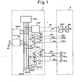
- a reference numeral 1 denotes a numerical control apparatus having an ordinary construction as a computer-equipped numerical control apparatus.
- a central processing unit CPU which may be a microprocessor is adapted to execute the desired numerical control process in accordance with the control program and machining program.
- a memory MEM has an area for storing or memorizing parameters such as acceleration and deceleration time constants, as well as other data such as present position of tool, an area for storing the control program, an area for storing data such an -4- as address corresponding to a contact signal transmitted from the machine side.
- a symbol PT represents a paper tape in which the machining program is stored by punching.
- a pulse distributor ITP is adapted to execute a known pulse distribution operation to produce distribution pulses Xp and Yp, upon receipt of feed speed command F and X and Y-axes displacement commands X and Y which are read out from the paper tape PT by a tape reader TR.
- a data input circuit DI incorporates receivers R 1 through R n adapted to receive signals transmitted from various limit switches, relays and so forth of the machine side, AND gates G 1 through G n and a decoder DEC 1 adapted to decode the address signals to open the desired AND gate.
- a data output circuit D 0 includes a multiplicity of latch circuits L 1 through L m for memorizing various commands such as a two-digit (eight bit) M function command in the form of .
- binary coded decimal (BCD) a two-digit S function command in the form of BCD
- a two-digit T function command in the form of BCD and so forth
- drivers D 1 through D m for corresponding ones of the latch circuits L 1 through L m , the drivers being adapted to send the latch circuit output signals to the machine tool
- a decoder DEC 2 which allows prescribed latch circuits to be set or reset upon decoding the address signals.
- a control signal BUS CBUS is provided for the exchange of control signals
- An address BUS for the transfer of address signals and a data BUS for transferring various data are represented by ABUS and DBUS, respectively.
- Cables 1 11 and 1 12 , 1 21 through 1 2n and 1 31 through 1 3m are provided for data exchange between the numerical control apparatus and the machine.
- a machine tool to be controlled in designated at a reference numeral 2.
- Servo control circuits SVX and SVY are adapted to drive the servo motors MX and MY upon receipt of the distribution pulses Xp and Yp, respectively.
- Symbols RC 1 through RC n represent, for example, relay contacts adapted to open and close in accordance with the states of over travel limit switches for X and Y directions, deceleration limit switches and so forth and deliver their outputs to the receivers R 1 through R n of the numerical control apparatus via the cables 1 21 through 1 2n .
- Relays RL 1 through RL m are adapted to operate in response to the drivers D 1 through D m of the numerical control apparatus so as to perform various machine controls such as spindle rotation control, spindle speed control, tool change control and so forth.
- the numerical controlling system shown in Fig. 1 operates in a manner described hereinunder.
- a machining program consisting of a multiplicity of blocks is stored in the paper tape PT by punching.
- the position command information (feed speed information F, position information X, Y) is read by the tape reader TR out of the blocks. This information F, X, Y is delivered to the pulse distributor ITP.
- the pulse distri- butorITP executes a known pulse distribution operation and produces output pulses Xp, Yp which are delivered to the machine side servo control circuits SVX, SVY through the cables 1 11 through 1 12 so as to drive the motors MX and MY thereby to control the movement of the movable part such as a tool, table or the like in accordance with the command.
- the processing unit delivers an address signal AD(m) corresponding to the M function to the address BUS ABUS, and transmits through the control signal BUS CBUS a control signal for actuating only the decoder DEC 2 .
- the processing unit delivers a signal "03" (0000 0011) to the data BUS DBUS.
- the address signal AD(m) is decoded by the decoder DEC 2 and only eight latches L 1 through L 8 for storing the two-digit (eight bit) M function command in the form of a binary coded decimal are turned into settable and resettable states.
- the data "03" (0000 0011) on the data BUS DBUS is set in the latches L 1 through L 8 .
- latches L 1 and L 2 are set while the latches L 3 through L 8 are reset.
- the data is then transmitted to the machine 2 via the cables 1 31 through 1 38 to effect the on/off control of the relays RL 1 through RL 8 .
- the machine 2 operates to turn the flow of coolant on.
- the reading of the contact signals RC 1 through RC n transmitted from the machine 2 to the numerical control apparatus is conducted as follows.
- Addresses AD(rC l ), AD(rC 2 ).. AD(rCn) corresponding to the contact signals RC 1 , RC 2 .. RCn are memorized in order in the address storage area of the memory MEM.
- the central processing unit CPU successively reads out the addresses AD(rC 1 ), AD(rC2) ,.. AD(rCn) making use of the idle time of each BUS line, and transmits the same to the address BUS ABUS.
- the central processing unit CPU transmits the control signal through the control signal BUS CBUS to make such a control as to permit only the decoder DEC 1 to operate.
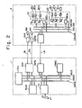
- Fig. 2 is a circuit block diagram of a circuit embodying the numerical controlling method and system of the present invention, in which the same reference numeri- cals are used to denote the same parts as those of the conventional system shown in Fig. 1, and detailed description of such parts is omitted.
- an interface circuit INFN incorporated in the numerical control apparatus 1 is adapted to convert the parallel information into serial information (this conversion is referred to as P/S conversion) and delivers the serial information as its output.
- the interface circuit INFN is further provided with conversion means for converting the serial information transmitted from the machine side in a bit-serial manner into parallel information (this conversion is referred to as S/P conversion).
- a direct memory access controller DMAC is adapted to make a direct access to the memory MEM and to write and read the data into and out of the latter, in accordance with the command issued from the central processing unit CPU. Namely, when the central processing unit CPU issues a command for a transfer of N-byte data from a predetermined address of the memory MEM, the direct memory access controller DMAC cyclically reads out the stored data byte by byte directly from the predetermined address, making use of the idle time of the BUS lines, and transmits the read-out data to the interface circuit INFN. The exchange of data between the machine 2 and the numerical control apparatus 2 is made through a cable LN.
- An interface circuit INFM incorporated in the machine 2 is provided with P/S conversion means and S/P conversion means as in the case of the interface circuit INFN of the numerical control apparatus 1.
- a control signal BUS, address BUS and data BUS of the machine side are represented by CBUSM, ABUSM and DBUSM, respectively.
- the numerical controlling system shown in Fig. 2 differs from the conventional system shown in Fig. 1 in the following points.
- M function command "M03" is read out of the paper tape PT by the tape reader TR.
- the following operation is performed even when another command such as S function command or T function command is read out.
- the two-digit signal "03" in the form of binary coded decimal (BCD) is stored at the predetermined address of the memory MEM adapted to store the two-digit M function command of BCD.
- the direct memory access controller DMAC which is ordered by the central processing unit CPU to cyclically read N-byte information out of addresses AD 1 through AD N , reads out this information from the memory MEM and delivers the same to the interface circuit INFN making use of the idle time of the BUS lines CBUS, ABUS and DBUS.
- the direct memory access controller DMAC reads the above-mentioned control signal, the address AD(m) and the data (BCD two-digit "03") out of the address ADl of the memory MEM and delivers the same to the interface circuit INFN.
- the interface circuit INFN delivers the information read out of the memory MEM to the interface circuit INFM of the machine 2 in a bit-serial manner through the cable LN, after a P/S conversion.
- the interface circuit INFM of the machine then effects an S/P conversion of the serial information, which has been transferred in the bit-serial manner and consists of the aforementioned control signal, address and the data, to convert the information into parallel information, and delivers the control signal, address AD(m) and the BCD two-digit data "03" to the control signal BUS CBUS, address BUS ABUS and the data BUS DBUS, respectively.
- the decoder DEC 2 becomes operative and decodes the address AD(m), so as to allow the setting and resetting of dnly the latches L 1 through L 8 which are adapted to store the two-digit M.function command (8 bit).
- the latches L 1 and L 2 are set, while the latches L 3 to L 8 are reset by the BCD two-digit data "03", so that the relays RL 1 and RL 2 are turned on, while the relays RL 3 through RL 8 are turned off through the action of the drivers D 1 through D 8 , so that the machine operation such as turning on of the flow of coolant is conducted.
- the control signal, address AD(m) and the BCD two-digit data have been described to be stored at a single or common address in the memory MEM, they may be stored at independent addresses.
- the transmission of the command such as M, S and T function commands from the numerical control apparatus to the machine 2 is conducted in the manner explained above.
- a control signal for permitting the operation of only the decoder DEC 1 is stored at a predetermined address ADj of the memory MEM, together with the address information AD(rC 18 ) corresponding to the contacts RC 1 through RC 8 , although the control signal and the address information AD(rC 18 ) may be stored at independent addresses.
- the direct memory access controller DMAC reads the control signal and the address information AD(rC 18 ) from the address AD. of the memory MEM and delivers the same to the interface circuit INFN through the data BUS.
- the interface circuit INFN then transmits, after a P/S conversion, the control signal and the address AD(rC 18 ) in a bit-serial manner through the cable LN to the interface circuit INFM of the machine 2.
- the interface circuit INFM then effects an S/P conversion of the bit-serially transmitted control signal and the address information AD(rC 18 ), and delivers the control signal and the address information to the control signal BUS CBUSM and to the address BUS ABUSM, respectively.
- the interface circuit INFM upon receipt of the 8-bit contact signal (data), effects a P/S conversion of the data and sends the same in a bit-serial manner to the interface circuit INFN of the numerical control apparatus 1, via the cable LN.
- the interface circuit INFN then effects an S/P conversion of the bit-serially transmitted data to send the same to the central processing unit CPU through the data BUS DBUS.
- the heading of other contact signals RC 9 through RC n is performed in the same manner, so that all contact signals are read by the numerical control apparatus 1.
- control signal, address and the data are stored at the same address of the memory.
- This, however, is not exclusive. Namely, it is possible to store the control signal, address and the data at different address and to read and bit-serially transfer them successively to the machine side.
- control BUS CBUS, CBUSM is not essential and can be neglected. In such a case, only the address and the data are transferred.
- the address signal is exchanged in a bit-serial manner between the numerical control apparatus 1 and the machine 2.
- the exchange of the address signal may be omitted if the machine 2 is provided with an address signal generating circuit adapted to be triggered by a synchronizing signal delivered by the numerical control apparatus 1 to the machine 2. Namely, the transfer of the address signal can be neglected by making the address signal generating circuit generate the address signal in synchronism with the transfer of the data read out from the memory MEM.
- Fig. 3 is a block diagram of a numerical controlling system constructed in accordance with another embodiment of the invention in which the address signal is generated at the machine side.
- the parts similar or identical to those of Fig. 2 are designated at the same reference numerals, and the detailed description thereof is omitted.
- a shift register SFR is adapted to make parallel writing and reading, as well as serial writing and reading.
- a gate GT controls the writing and reading of the data into and out of the shift register SFR.
- a transfer control circuit TRCN produces a clock pulse CLK - in the transfer of the data and produces a synchronization signal SYNC in advance of the operation of the direct memory access controller DMAC (Fig. 2).
- the transfer control circuit TRCN is further adapted to control the state of the gate circuit GT by generating a gate signal GS upon in accordance with an address signal which is delivered through the address BUS ABUS.
- a shift register /permits, as in the case of the aforementioned shift register SFR, parallel writing and reading, as well as serial writing and reading, of the data.
- a bit counter BTC has a capacity equal to the bit number (8 bit) of one item of parallel data, and is adapted to count the clock pulses delivered by the numerical control apparatus 1. The bit counter produces one carry pulse CP each time it counts 8 (eight) clock pulses CLK, i.e. at each transfer of 8-bit data.
- An address counter ADC counts the carry pulses CP and delivers the counted number to the address BUS ABUSM as the address signal.
- central processing unit CPU central processing unit CPU
- memory MEM direct memory access controller DMAC
- pulse distributor ITP pulse distributor ITP
- tape reader TR data input circuit DI
- data output circuit DO relays RL 1 through RL m
- contacts RC 1 through RC m and so forth are included by the system shown in Fig. 3.
- a synchronization signal SYNC is generated by the transfer control circuit TRCN of the numerical control apparatus 1. This signal SYNC is transmitted to the machine 2 through the cable L 2 and is applied to the address counter ADC and the bit counter BTC to make the initial clear of the contents of these counters.
- the direct memory access controller DMAC starts to operate to successively read out the data from the memory (Fig. 2) and writes this data in a parallel manner in the shift register SFR. Thereafter, this data is transmitted to the data cable L o while being shifted bit-by-bit by the clock pulse CLK. Namely, the parallel data is converted into serial data DATA and is transmitted in a bit-serial manner. Simultaneously, the clock pulses CLK are transmitted through the cable L l in order to show the positions of the serial data DATA.
- the transmitted serial data DATA is sampled by the clock pulses CLK.
- the sampled data is then serially written in the shift register SFRM while being shifted bit-by-bit and is then subjected to an S/P conversion.
- the clock pulse CLK is delivered to the bit counter BTC so that the number of the clock pulses CLK is counted by the bit counter BTC.
- the bit counter BTC produces the carry pulse CP as it counts 8 (eight) clock pulses the length of which corresponds to the length (8 bit) of the bit-serially transmitted data, and the address counter makes one carry by this carry pulse.
- the S/P conversion of the serial data DATA is completed by one carry of the address counter ADC, and the data is written from the shift register SFRM in a parallel manner into the latches L 1 through L 8 (Fig. 2) corresponding to the number counted by the address counter ADC, i.e. corresponding to the first address.
- the content of the address counter ADC is carried step by step so that the address counter produces the first address signal, second address signal and the i-th address signal which select the corresponding latches.
- the clock pulses CLK may be produced at the machine side in response to the synchronization signal SYNC.
- the signal to be transferred is exchanged in a bit-serial manner between the numerical control apparatus and the machine, after a P/S conversion, so that the number of cables is remarkably reduced and the wiring work is very much facilitated, while attaining a high reliability of the signal exchange.
- the data.transfer time is further shortened if such an arrangement is adapted that the synchronization signal is transmitted to the machine in place of the address to permit the machine to generate the address signal by itself.
- the load imposed on the central processing unit CPU is remarkably reduced if the numerical control apparatus incorporates the direct memory access controller DMAC, because, by so doing, the exchange of data between the machine and the numerical control apparatus is made under the control of the direct memory access controller DMAC.
Landscapes
- Engineering & Computer Science (AREA)
- Human Computer Interaction (AREA)
- Manufacturing & Machinery (AREA)
- Physics & Mathematics (AREA)
- General Physics & Mathematics (AREA)
- Automation & Control Theory (AREA)
- Numerical Control (AREA)
Applications Claiming Priority (2)
| Application Number | Priority Date | Filing Date | Title |
|---|---|---|---|
| JP113254/79 | 1979-09-04 | ||
| JP11325479A JPS5636709A (en) | 1979-09-04 | 1979-09-04 | Numerical control system |
Publications (3)
| Publication Number | Publication Date |
|---|---|
| EP0025666A2 true EP0025666A2 (de) | 1981-03-25 |
| EP0025666A3 EP0025666A3 (en) | 1981-04-01 |
| EP0025666B1 EP0025666B1 (de) | 1986-12-10 |
Family
ID=14607480
Family Applications (1)
| Application Number | Title | Priority Date | Filing Date |
|---|---|---|---|
| EP80303063A Expired EP0025666B1 (de) | 1979-09-04 | 1980-09-03 | Verfahren und System zur numerischen Steuerung |
Country Status (4)
| Country | Link |
|---|---|
| US (1) | US4368511A (de) |
| EP (1) | EP0025666B1 (de) |
| JP (1) | JPS5636709A (de) |
| DE (1) | DE3071859D1 (de) |
Cited By (3)
| Publication number | Priority date | Publication date | Assignee | Title |
|---|---|---|---|---|
| EP0053771A3 (de) * | 1980-12-05 | 1984-04-18 | KEARNEY & TRECKER CORPORATION | Tragbarer Steuerkoffer für numerisch gesteuerte Werkzeugmaschinen |
| EP0224588A4 (de) * | 1985-03-30 | 1989-07-26 | Fanuc Ltd | Numerisch gesteuerte werkzeugmaschine. |
| EP0550864A1 (de) * | 1991-12-19 | 1993-07-14 | Mitsubishi Denki Kabushiki Kaisha | Übertragungssteuervorrichtung |
Families Citing this family (10)
| Publication number | Priority date | Publication date | Assignee | Title |
|---|---|---|---|---|
| JPS5851306A (ja) * | 1981-09-22 | 1983-03-26 | Fanuc Ltd | 数値制御装置 |
| JPS59174916A (ja) * | 1983-03-25 | 1984-10-03 | Mitsubishi Electric Corp | 数値制御装置 |
| JPS6054009A (ja) * | 1983-09-02 | 1985-03-28 | Amada Co Ltd | バス接続型プログラマブルコントロ−ラ |
| JPS6120104A (ja) * | 1984-07-06 | 1986-01-28 | Fanuc Ltd | 数値制御方式 |
| JPS63298404A (ja) * | 1987-05-28 | 1988-12-06 | Fanuc Ltd | 機械インタ−フェイス回路 |
| JP3308386B2 (ja) * | 1994-04-25 | 2002-07-29 | ファナック株式会社 | 制御システム |
| DE10104712C1 (de) * | 2001-02-02 | 2002-12-12 | Siemens Ag | Steuerungsverfahren sowie Regelungsstruktur zur Bewegungsführung, Vorsteuerung und Feininterpolation von Objekten in einem Drehzahlreglertakt, der schneller als der Lagereglertakt ist |
| JP2005108082A (ja) * | 2003-10-01 | 2005-04-21 | Okuma Corp | デバイスドライバのインターフェース方法 |
| JP4388427B2 (ja) * | 2004-07-02 | 2009-12-24 | オークマ株式会社 | スクリプト言語で記述されたプログラムを呼出し可能な数値制御装置 |
| US7945745B2 (en) | 2007-09-17 | 2011-05-17 | General Electric Company | Methods and systems for exchanging data |
Family Cites Families (12)
| Publication number | Priority date | Publication date | Assignee | Title |
|---|---|---|---|---|
| US3898373A (en) * | 1971-09-09 | 1975-08-05 | Leo F Walsh | Data communication system |
| DE2150397B1 (de) * | 1971-10-09 | 1973-03-01 | Licentia Gmbh | Numerische Arbeitsmaschinensteuerung |
| US3895355A (en) * | 1972-06-05 | 1975-07-15 | Shorell Limited | Pattern control system |
| DE2445814A1 (de) * | 1974-09-25 | 1976-04-08 | Siemens Ag | Einrichtung zur korrektur und/oder ergaenzung von aus einem mechanischen datentraeger entnehmbaren informationen |
| US4071911A (en) * | 1975-04-22 | 1978-01-31 | Continental Can Co. Inc. | Machine control system with machine serializing and safety circuits |
| US4078196A (en) * | 1976-03-01 | 1978-03-07 | Vapor Corporation | Digital valve and pump control system |
| US4065662A (en) * | 1976-05-26 | 1977-12-27 | Peripheral Dynamics, Inc. | Card reader system with improved interface |
| US4107785A (en) * | 1976-07-01 | 1978-08-15 | Gulf & Western Industries, Inc. | Programmable controller using microprocessor |
| US4200936A (en) * | 1976-08-17 | 1980-04-29 | Cincinnati Milacron Inc. | Asynchronous bidirectional direct serial interface linking a programmable machine function controller and a numerical control |
| US4064395A (en) * | 1976-08-17 | 1977-12-20 | Cincinnati Milacron Inc. | Machine control system employing a programmable machine function controller |
| JPS5438482A (en) * | 1977-08-31 | 1979-03-23 | Toshiba Corp | Group control system |
| US4215395A (en) * | 1978-08-24 | 1980-07-29 | Texas Instruments Incorporated | Dual microprocessor intelligent programmable process control system |
-
1979
- 1979-09-04 JP JP11325479A patent/JPS5636709A/ja active Pending
-
1980
- 1980-09-02 US US06/183,038 patent/US4368511A/en not_active Expired - Lifetime
- 1980-09-03 EP EP80303063A patent/EP0025666B1/de not_active Expired
- 1980-09-03 DE DE8080303063T patent/DE3071859D1/de not_active Expired
Cited By (4)
| Publication number | Priority date | Publication date | Assignee | Title |
|---|---|---|---|---|
| EP0053771A3 (de) * | 1980-12-05 | 1984-04-18 | KEARNEY & TRECKER CORPORATION | Tragbarer Steuerkoffer für numerisch gesteuerte Werkzeugmaschinen |
| EP0224588A4 (de) * | 1985-03-30 | 1989-07-26 | Fanuc Ltd | Numerisch gesteuerte werkzeugmaschine. |
| EP0550864A1 (de) * | 1991-12-19 | 1993-07-14 | Mitsubishi Denki Kabushiki Kaisha | Übertragungssteuervorrichtung |
| US5507004A (en) * | 1991-12-19 | 1996-04-09 | Mitsubishi Denki Kabushiki Kaisha | Communication control system for either providing blank areas or overwriting areas in a receiving RAM depending on deficient or execess word counts in received frames |
Also Published As
| Publication number | Publication date |
|---|---|
| EP0025666B1 (de) | 1986-12-10 |
| JPS5636709A (en) | 1981-04-10 |
| DE3071859D1 (en) | 1987-01-22 |
| US4368511A (en) | 1983-01-11 |
| EP0025666A3 (en) | 1981-04-01 |
Similar Documents
| Publication | Publication Date | Title |
|---|---|---|
| US4396987A (en) | Machine tool and robot control apparatus | |
| CA1325683C (en) | Peer-to-peer register exchange controller for plcs | |
| EP0025666B1 (de) | Verfahren und System zur numerischen Steuerung | |
| US4616307A (en) | Programmable controller alarm display method | |
| EP0034017A2 (de) | Programmierbare Folgesteuervorrichtung | |
| US4109188A (en) | Index device for tool storage magazine | |
| JPS6224802B2 (de) | ||
| EP0089193B1 (de) | Verfahren und Gerät zum Anzeigen von Leiterdiagrammen | |
| EP0088804B1 (de) | Numerische steuereinheit | |
| US3657627A (en) | Tool selection system | |
| US5126956A (en) | Method and apparatus for displaying segments of a ladder diagram which turn on an operator specified relay | |
| EP0137852A1 (de) | Numerisches kontrollsystem | |
| US4096563A (en) | Machine tool control system and method | |
| US4396973A (en) | Programmable sequence controller | |
| EP0074412B1 (de) | Numerische steuereinheit | |
| EP0097444A2 (de) | Verfahren zur Anzeige eines Leiterdiagrams | |
| EP0092312B1 (de) | Verfahren und Gerät zum Anzeigen von Leiterdiagrammen | |
| US5136496A (en) | Master/slave numerical control apparatus in which the master can identify types and order of the slaves | |
| KR830002111B1 (ko) | 수치제어 방법 | |
| US4090120A (en) | Method and means for controlling energization by commands | |
| EP0089194B1 (de) | Verfahren und Gerät zum Anzeigen von Leiterdiagrammen | |
| SU1605211A1 (ru) | Устройство дл программного управлени объектом | |
| SU744465A1 (ru) | Устройство дл числового программного управлени станком | |
| JP2664492B2 (ja) | Cncの協調動作方式 | |
| US3158429A (en) | System for recording registered data |
Legal Events
| Date | Code | Title | Description |
|---|---|---|---|
| PUAI | Public reference made under article 153(3) epc to a published international application that has entered the european phase |
Free format text: ORIGINAL CODE: 0009012 |
|
| PUAL | Search report despatched |
Free format text: ORIGINAL CODE: 0009013 |
|
| AK | Designated contracting states |
Designated state(s): DE FR GB |
|
| AK | Designated contracting states |
Designated state(s): DE FR GB |
|
| RBV | Designated contracting states (corrected) |
Designated state(s): DE FR GB |
|
| 17P | Request for examination filed |
Effective date: 19810915 |
|
| RAP1 | Party data changed (applicant data changed or rights of an application transferred) |
Owner name: FANUC LIMITED |
|
| RAP1 | Party data changed (applicant data changed or rights of an application transferred) |
Owner name: FANUC LTD |
|
| GRAA | (expected) grant |
Free format text: ORIGINAL CODE: 0009210 |
|
| AK | Designated contracting states |
Kind code of ref document: B1 Designated state(s): DE FR GB |
|
| REF | Corresponds to: |
Ref document number: 3071859 Country of ref document: DE Date of ref document: 19870122 |
|
| ET | Fr: translation filed | ||
| PLBE | No opposition filed within time limit |
Free format text: ORIGINAL CODE: 0009261 |
|
| STAA | Information on the status of an ep patent application or granted ep patent |
Free format text: STATUS: NO OPPOSITION FILED WITHIN TIME LIMIT |
|
| 26N | No opposition filed | ||
| PGFP | Annual fee paid to national office [announced via postgrant information from national office to epo] |
Ref country code: GB Payment date: 19910806 Year of fee payment: 12 |
|
| PGFP | Annual fee paid to national office [announced via postgrant information from national office to epo] |
Ref country code: FR Payment date: 19910813 Year of fee payment: 12 |
|
| PGFP | Annual fee paid to national office [announced via postgrant information from national office to epo] |
Ref country code: DE Payment date: 19910910 Year of fee payment: 12 |
|
| PG25 | Lapsed in a contracting state [announced via postgrant information from national office to epo] |
Ref country code: GB Effective date: 19920903 |
|
| GBPC | Gb: european patent ceased through non-payment of renewal fee |
Effective date: 19920903 |
|
| PG25 | Lapsed in a contracting state [announced via postgrant information from national office to epo] |
Ref country code: FR Effective date: 19930528 |
|
| PG25 | Lapsed in a contracting state [announced via postgrant information from national office to epo] |
Ref country code: DE Effective date: 19930602 |
|
| REG | Reference to a national code |
Ref country code: FR Ref legal event code: ST |