EP0025729A1 - Schalter mit mehreren Lagen von Kreuzungspunkten - Google Patents
Schalter mit mehreren Lagen von Kreuzungspunkten Download PDFInfo
- Publication number
- EP0025729A1 EP0025729A1 EP80401188A EP80401188A EP0025729A1 EP 0025729 A1 EP0025729 A1 EP 0025729A1 EP 80401188 A EP80401188 A EP 80401188A EP 80401188 A EP80401188 A EP 80401188A EP 0025729 A1 EP0025729 A1 EP 0025729A1
- Authority
- EP
- European Patent Office
- Prior art keywords
- plug
- head
- rod
- plies
- switch according
- Prior art date
- Legal status (The legal status is an assumption and is not a legal conclusion. Google has not performed a legal analysis and makes no representation as to the accuracy of the status listed.)
- Granted
Links
Images








Classifications
-
- H—ELECTRICITY
- H04—ELECTRIC COMMUNICATION TECHNIQUE
- H04Q—SELECTING
- H04Q1/00—Details of selecting apparatus or arrangements
- H04Q1/02—Constructional details
- H04Q1/14—Distribution frames
- H04Q1/145—Distribution frames with switches arranged in a matrix configuration
-
- H—ELECTRICITY
- H01—ELECTRIC ELEMENTS
- H01H—ELECTRIC SWITCHES; RELAYS; SELECTORS; EMERGENCY PROTECTIVE DEVICES
- H01H67/00—Electrically-operated selector switches
- H01H67/22—Switches without multi-position wipers
- H01H67/26—Co-ordinate-type selector switches not having relays at cross-points but involving mechanical movement, e.g. cross-bar switch, code-bar switch
-
- H—ELECTRICITY
- H02—GENERATION; CONVERSION OR DISTRIBUTION OF ELECTRIC POWER
- H02B—BOARDS, SUBSTATIONS OR SWITCHING ARRANGEMENTS FOR THE SUPPLY OR DISTRIBUTION OF ELECTRIC POWER
- H02B1/00—Frameworks, boards, panels, desks, casings; Details of substations or switching arrangements
- H02B1/20—Bus-bar or other wiring layouts, e.g. in cubicles, in switchyards
- H02B1/207—Cross-bar layouts
Definitions
- the present invention relates to a matrix switch with several layers of crossing points usable in particular in telephone or other distributors, or in similar devices. More particularly, the invention relates to such a switch with selection by coordinates.
- Cross bar telephone switches have been known for a long time. Recently, multi-layer switches have been developed such as those described in French patents 1,584,604 and 2,106,738. These switches consist of several first layers of parallel wires oriented in a first direction and of several second layers of parallel wires interposed between the first layers and oriented in a direction perpendicular to the first layers. We thus define, in a direction normal to the plies of wires, multiple crossing points which are open or closed by sorts of multi-contact plugs displaced perpendicular to the plies. In French patent 2,038,444, multicontact plugs are also used which are rotated to close or break the contacts. These switches have been designed to constitute fast-functioning switches involved in establishing communications between subscribers.
- An object of the present invention is to provide a switch for making distributors while avoiding the drawbacks mentioned above.
- Another object of the invention consists in providing a matrix switch with several layers of plug crossing points usable in particular in telephone distributors, which avoids the drawbacks mentioned above and which can be automated in a relatively simple manner.
- Another object of the invention consists in providing a switch of this type, the switching plugs of which can be twisted to establish or break contacts.
- Another object of the invention consists in providing a control member capable of selectively rotating a switching plug in the matrix of plugs associated with the crossing points of the switching matrix.
- a switch with several layers of crossing points consisting of several first plies of parallel wires oriented in a first direction and several second plies of wires oriented in a direction perpendicular to the first plies, the first and second plies being interposed, each ply of wires being carried by a grid of insulating material with square meshes, each mesh being crossed by a wire parallel to one of its sides, the grids of the second plies being angularly offset by a quarter turn, all in the same direction, by relative to the grids of the first layers, a crossing point consisting of two superimposed adjacent meshes and a conductive surface of a plug electrically connecting the wire segment of the upper mesh to the wire segment of the lower mesh.
- each plug inserted in a stack of crossing points comprises as many conductive cylindrical rings as superimposed crossing points, each ring having a height adapted to constitute the conductive surface of a single crossing point.
- each plug inserted in a crossover point stack comprises as many sectors of conductive cylindrical rings as superimposed crosspoints, each ring sector having a height and an angle at the apex adapted to constitute the conductive surface of a crossing point.
- the sheets include crescent-shaped heads whose horns cooperate with the flexible teeth of selection bars deformable by the teeth of work bars, the selection and work bars being crossed, each selection bar pushed in a determining direction with each work bar at work the rotation of a plug head by a quarter turn in one direction, and pulled in the other direction determining with a work bar adjacent to work the rotation of said head a quarter turn in the other direction.
- Another object of the present invention is to provide a control member for the rotary plug heads which requires access only on one face of the switch, while retaining the advantages of the above switches.
- Another object of the invention is to provide a control of movable plug heads in translation, which also requires access only on one side of the switch, while retaining the advantages of the above switches.
- a switch comprising a switching member comprising two parallel rods whose active ends are each provided with a hook which can be lowered (or mounted) in conjunction with a translational movement of the corresponding rod, the hook of a lowered (or mounted) rod driving one of the two hooking faces of the head of a switching plug in one direction, which turns the plug a quarter of a turn in a sense, the hook of the other rod lowered (or mounted) causing the other hooking face, which turns the plug a quarter of a turn in the other direction.
- each rod has the shape of a flat head connected to the body of the rod by a flexible part, the head carrying a lug engaged in a slot in a rigid plate of the member control, the slot having, in a vertical plane, the shape of an S, such that the translational movement of the rod in the member which causes the movement of the lug in the slot, makes that descend (or raise) that -this, then finish its course with a simple movement of translation, the hook of the head describing a trajectory parallel to that of the lug.
- the heads of the plugs comprise a cylindrical lower part and an upper part in the form of a circular sector having a cylindrical bulge at its center, the sector having an angle at the center slightly less than 180 °.
- the center of the cylindrical bulge is surmounted by a conical pin.
- a switch comprising a switching member comprising two parallel rods, the active ends of which are each provided with a pusher which can be lowered (or mounted) in conjunction with a translational movement of the corresponding rod, the lowered (or mounted) pusher driving one of the lateral sides of the frame forming the head of the plug, which lowers (or raises) the plug in the stack, a rod being associated with a pusher which descends and another to an upward push button.
- the switch element of FIG. 1 is constituted by a square grid 1 made of insulating plastic material having square openings 2 forming alignments parallel to the external sides 3 to 6 of the grid. In the alignments, the openings 2 are regularly spaced.
- Metal bands or beams 7 pass right through the grid 1 perpendicular to the sides 3 and 5. Each beam 7 crosses an alignment of openings 2 parallel to the sides 4 and 6, with in each opening crossed an apparent segment 8. The height of each beam 7 is less than the thickness of the grid 1 with its longitudinal axis in the median plane of the grid.
- the associated segment 8 does not pass through the center of the opening 2, but is offset by a distance r less than the side of the opening.
- the ends 9 of the beams 7, which are outside the grid, are used to connect the beams to connecting cables.
- the beams 7 are electrically conductive and made of a material whose elasticity is compatible with a reasonable contact pressure.
- Sheet 49 of FIG. 2 is a plug of a known type. It comprises a cylindrical body around which are provided circular contact rings 50 of the same height as 25 and separated from one another as 25, 26 and 27. The head 51 of 49 does not have a slot.
- the plug 49 is designed to be inserted manually in the stack 35 to create contacts by plugging in, which can be advantageous in rudimentary switches. In this case, to saturate a matrix, it suffices a number of sheets 49 equal to the numbers of beams on the shortest side of the matrix.
- FIG. 3 shows a stack of grids 10 to 15, all identical to grid 1.
- the plies 16, 18 and 20 of the grids 10, 12 and 14 are oriented in a direction perpendicular to the plies 17, 19 and 21 grids 11, 13 and 15.
- FIG. 3 also shows a plug 22 comprising a cylindrical body 23 provided with a head 24, the assembly of 23 and 24 being made of insulating plastic.
- the body 23 carries contact strips 25, 26 and 27, all identical, made of metal or a good conductive alloy.
- the contact strips 25 to 27 are regularly spaced along the body. They do not completely surround the body 23 and have a height of the order of the thickness of a grid plus the height of a beam 7.
- Fig. 4 the cross section of the plug 22 has been shown in the plane passing through the strip 25. It appears that the diameter of the body 23 is less than a + h so that the body 23 alone can be introduced into a grid opening without simultaneously carrying on the edges of the grid and the beam segment 8.
- the section of the strip 25 is substantially in an arc of 270 °, the diameter of the circle of 25 being greater than that of 23.
- the extreme edges 28 and 29 of 25 are wound on themselves and are lodged in longitudinal grooves 30 and 31 hollowed out in the body 23. Given the difference in diameter between 25 and 23, the strip 25 progressively moves away from the surface of 23 from from its edges 28 and 29.
- the diameter of 25 is such that the whole of the body 23 and of the strip 25 comes into contact with the sides of the square defined by the beam 16, the beam 17 and the faces of the corresponding openings. Under these conditions, the strip 25 deforms and balances each contact, allowing easier rotations.
- the height of the strip 25 is greater than the thickness of a grid, but less than twice this thickness. Therefore, the strip 25 can come into contact, at the same time, with the beams 16 and 17.
- FIG. 4 shows the plug 22 in the working position, 25 being in contact with 16 and 17. It also shows a second plug 32, identical to 22, but turned a quarter of a turn, in an anticlockwise direction , so that 25 is only in contact with 17. The plug 32 is in the rest position.
- the head 24 of the plug 22 is provided with a slot 33 making it possible to turn the plug a quarter of a turn anticlockwise or in the direct direction to put it at rest or again at job. Note that if we turn plug 22 of a quarter turn clockwise, it remains in the working position. In practice, as will be seen below in describing the control device, the plug 22 can only take two positions, without ambiguity.
- each grid includes 4x4 openings 2 allows the insertion of four plugs, such as 22, to make four separate connections.
- the stack of FIG. 3 has only been shown as an example to illustrate the basic structure of the switch according to the invention.
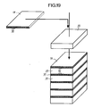
- a stack 34 formed from elongated grids, such as the grid 35 shown before it is placed on the stack.
- the grid 35 has a rectangular shape comprising four lines of openings 2, each line having 19 openings.
- the grid 35 is crossed by a sheet of four conductive beams 36 each of which passes respectively through a line of openings, parallel to the length of the grid 35.
- the respective positions of the bare segments of the beams are identical to those of the grid 1.
- the grid 35 differs from the grid 1 only in that in one direction it has a greater number of openings.
- the stack 34 is formed of eight levels 37 to 44, each level being formed by four grids 35 arranged parallel next to each other, their long sides being adjacent. In each level, the adjacent grids 35 are separated from each other by an interval t equal to the pitch of the openings in the grid 35.
- the grids of the odd levels 37, 39, 41 and 43 are oriented in the same direction while that the grids of even levels 38, 40, 42 and 44 are oriented in the perpendicular direction.
- the levels being superimposed, the openings create vertical alignments as in the stack of Fig. 2.
- a grid of the type of that of 35 consists of n lines of holes, which corresponds to a sheet of n conductive beams parallel to the pitch p.
- Each line can include g holes.
- Length and width are then obtained by multiplying n and g by the step E.
- a basic grid may include a sheet of 10 conductors with a pitch of 5mm. Each conductor has a section of 1 x 0.2 mm and the grid with a thickness of 2.5 mm is overmolded on the sheet.
- the length of a grid can reach 120 steps or more. To obtain the grids, a very long strip is made overmolded on a sheet of wire, then the strip is cut to the desired length.
- Fig. 6 shows a cylindrical post 45 provided at a crossing point of two bars 46 and 47 of the grid 35 on one face of this grid.
- a cylindrical blind hole 48 is provided on the other face of the grid, opposite the tenon 45.
- the grid 35 thus comprises a certain number of torque composed of a tenon 45 and a blind hole 48, and it the same is true of the other grids of the stack 34.
- These couples are provided to ensure the correct positioning of the superimposed grids, a lug 45 of a lower grid coming to be housed in a corresponding hole of the immediately upper grid.
- the distribution of couples takes into account the fact that a level to another the direction of the grids changes and that empty intervals are provided between grids parallel to one level.
- the tenons and the holes are made during the overmolding of the beams 36 to obtain the grid.
- the cell 35 thus obtained is rigid and solid, and, moreover, practically dustproof.
- a stack 35 comprising eight levels.
- fourteen levels are required, which leads to a thickness of 10 mm.
- a battery 35 which is capped with a control module 52.
- the control module supports the heads of the switching plugs which are inserted in the holes of the battery 35 when the module 52 is installed
- the module 52 comprises selection bars 53 which cross it right through and whose first ends are visible on the side 54 of the module. It also includes control bars 55 which pass right through it and whose first ends are visible on the side 56 of the module. We will see in the following how by pushing or pulling these bars 53 and 55 in an adequate way, we can turn the plugs a quarter of a turn to the right or to the left, to obtain the closing or opening of crossing in the matrix formed by the stack 35.
- the sections of the bars 55 are in the form of an inverted T, the soles of the T serving to retain the heads of the plugs.
- the module 52 is, moreover, provided on its upper face with studs, not shown, of the type 45 and has holes 48 on its lower face. Thus, by its holes 48, the module 52 fits well on the first level of 35.
- Fig. 8 shows that it is possible to constitute columns of stacks 35, respectively surmounted by their modules 52, stacked one on the other.
- the lugs 45 of the modules 52 allow the positioning of the stack immediately above. Obviously, such a column is only feasible because the bars 53 and 55 of the control modules are accessible from the sides.
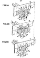
- Figs. 9a to 9b illustrate the structure of a control module 52, as well as its operation.
- a conductive beam 57 carried by a bar 58 of a grid 35
- a conductive beam 59 carried by a bar 60 of another grid 35 placed under the first and oriented perpendicularly
- a plug 61 constituted by a body 62, similar to 23, and a head 63.
- the body 62 carries a contact strip 64, similar to 25.
- the head 63 has a cylindrical bottom part 65, which rests on the edges of the soles of the control bars 55 adjacent to T profile and a crescent-shaped upper part 66 having a cylindrical bulge at its center.
- FIG. 10 which is a plan view, schematically shows a certain number of heads 64 showing, for each one a crescent 66 comprising a cylindrical external part of the same diameter as 65, two horns 67a and 67b, as well as the bulged cylindrical part 68 of which the axis coincides with that of 65.
- Each horn 67a or 67b is connected to the cylinder 68 by a concave surface 69a and 69b.
- the ends of the horns 67a and 67b intervene directly in the state switching of the plug, while the central part 68 is only retained to make the crescent less fragile.
- a selection bar 53 and two control bars 55a and 55b have also been shown.
- the control bar 53 is parallel to the beam 57 while the bars 55a and 55b are parallel to the beam 59. More specifically, the bar is in the vertical plane of the bar, not shown, parallel to 60 on the other side of the plug 61, the bar 55a is in the vertical plane of the bar 58, and the bar 55b is in the vertical plane of the bar, not shown, parallel to 58 on the other side of the plug 61.
- the selection bar 53 has the shape of a comb, the teeth 70a, 70b, 70c, etc., are flexible and are arranged in a pitch equal to the pitch of the grids.
- the back of the comb 53 is located substantially above the top of the heads 64 of the plugs 61 and the teeth are long enough so that their lower parts are at the level of the horns 67a and 67b, but above the base 65.
- Each bar control 55a or 55b carries rigid teeth, such as 71a and 71b, which are distributed along the bar following the pitch of the grids.
- the bottom of the bar 55a or 55b is below the base 65 and the top of the teeth 71a or 71b is at a level higher than the bottom of the teeth 70a, 70b, ...
- the selection bar 53 is placed so that each tooth 70a, 70b, 70c, etc., is respectively opposite the axis of a plug 61.
- the control bars 55a and 55b are placed so that the teeth are respectively opposite the axes of the plugs.
- the width of a tooth 70a, 70b, etc. is such that, in the position indicated, the control bars 55a and 55b can be moved without the teeth 71a or 71b touching the teeth 70a or 70b, but passing freely between them.
- the bar 53 can be moved with its teeth passing between the teeth of the control bars.
- the plug 61 is in a position such that the horn 67a is further from the tooth 70b than the horn 67b.
- the contact strip 64 is then in contact only with the beam 57 and the current cannot pass from 57 to 59.
- FIG. 9b illustrates the operation of the switching which switches the plug 61 from the rest state to the working state.
- the bar 53 is first of all pushed in the direction of the arrow F1, by means not shown, so that the part of the tooth 70b which was in front of the horn 67a comes in front of the horn 67b.
- the other part of the tooth 70b is then in front of the tooth 71b of the working bar 55b.
- the bar 55b is pushed, in the direction of the arrow F2, so that the tooth 71b pushes the flexible bottom of the tooth 70b, which comes into contact with the horn 67b of the head of the plug, then pushes this horn which causes the rotation of the plug 61.
- the stroke of the working bar 55b is such that the plug 61 rotates a quarter of a turn, so that the contact strip 64 comes into contact, at the same time, with the beams 57 and 59.
- the current can pass from 57 to 59.
- the bar 55b is released so that it returns to its initial position in FIG. 9a, for example under the action of a return spring not shown.
- the selection bar 53 is released and returns to its initial position, for example also under the action of a spring. reminder.
- the plug 61 keeps the position it has reached during the switching so that the contact is maintained without external energy supply and without causing mechanical stress, as in some switches where an element remains stuck in extension.
- FIG. 9c illustrates the operation of the switching which switches the plug 61 from the working state to the resting state.
- the bar 53 is firstly pulled in the direction of the arrow F3, by means not shown, so that the part of the tooth 70b which was, at rest, in front of the horn 67b comes in front of the horn 67a.
- the other part of tooth 70b is then in front of tooth 71a of the work bar 55a.
- the bar 55a is pushed, in the direction of the arrow F2, so that the tooth 71a pushes the flexible bottom of the tooth 70b, which comes into contact with the horn 67a of the head of the plug, then pushes this horn which causes the rotation of the plug 61.
- the stroke of the working bar 55a is such that the plug 61 turns backwards by a quarter of a turn, so that it returns to the rest position indicated in FIG . 9a. Then, the selection bars 53 and working bars 55a are released, as described in relation to FIG. 9b.
- Fig. 10 which partially shows a matrix of file heads 61 associated with a selection busbar 53.1, 53.2, 53.3, ..., and a working busbar 55.1, 55.2, 55.3, ..., makes it possible to illustrate the operation of a module 52.
- the selection bars 53.1 to 53.5 are each represented by a small horizontal rectangle, to the right of the matrix, with, in its horizontal extension, double horizontal lines symbolizing the flexible teeth 70 of the bars.
- the working bars 55.1 to 55.6 are each represented by a small vertical rectangle, under the matrix, with, in its vertical extension, a series of small vertical rectangles symbolizing the rigid teeth 71 of the bars.
- the vertical line 72 indicates the position of the ends of the selection bars and the horizontal line 73 that of the ends of the working bars at rest.
- the bar 53.2 has been pushed towards the die, in the position indicated in FIG. 9b, then the work bar 55.5 has been pushed as in FIG. 9b, so that the head of the card for the second row and the fourth column has been turned in the direction of the arrow - that is to say, put to work.
- Bar 53.4 has, on the contrary, has been pulled out of the die and the bar 55.2 has been pushed, as in FIG. 9c, so that the head of the card of the fourth row and of the second column is turned in the direction of the arrow, that is to say put to rest.
- each level can be manufactured in a modular fashion, the basic modular element 35 consisting of a sheet of conductors parallel to the pitch p.
- the connections of the inputs and outputs can be made respectively on the faces of the parallelepiped of FIG. 8, which correspond respectively to the sides 56 and 54 of the modules 52, the other two faces being able to be used for testing the circuitry as well as for controlling the bars 53 and 55.
- Fig. It highlights the advantages of this type of battery. If we share the stack along an axis passing through a diagonal which leaves on the same side 54 and 56, we delimit two zones 74 and 75, i.e. zone 74 devolved to the line and installation teams, and the zone 75 reserved for the operating department. In zone 74, the side 56 receives the incoming cable conductors 76 and the side 54 receives the outgoing cable conductors 77 to the central office. Certain inter-matrix connections are possible in the factory. The other two sides 72 and 73 are assigned to the command and to the tests (link interruption, realization of bypass, etc.).
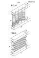
- Fig. 12 there is shown a series of batteries of FIG. 8 mounted vertically between two cable trays 78 and 79 respectively for the incoming cables 76 and the outgoing cables 77.
- the stacks are oriented so that their diagonals are aligned, all leaving the installation area 74 on one side and on the other side, the operating area 75.
- a series of batteries of FIG. 8 mounted horizontally on means not shown, between two cable channels 80 and 81 similar to 78 and 79.
- the diagonal planes of the stacks are aligned to separate the zones 74 and 75.
- Fig. 14 shows two distributor bays formed from stacks of FIG. 8, in which the dies are mounted on a vertical axis 82 which makes it possible to extract them from the stack by rotating them, as indicated by the arrows, to have access to the entire surface of each matrix when it is desired to establish or break a connection by acting on the plug heads.
- the cables are passed through a chute 83 and therefore undergo twists with each operation of the matrix.
- each bay comprises two stacks of dies with, at the rear, in the central part, the cable trays 84.
- the management principle remains the same, the dies being articulated on the same vertical axis 85 and being arranged symmetrically with respect to to this one.
- This arrangement of FIG. 15 should take up less space than that of FIG. 14.
- FIG. 16 a fully automated distributor bay, the visible side of the stack overlooking the operating area.
- the matrices are fixed.
- the member 87 has the shape of a right angle whose plane is perpendicular to that of the rails 85 and 86, and is therefore parallel to those of the levels of the dies or also in the plane of the control devices 52.
- the rails 85 and 86 can carry racks on which roll gear wheels mounted at the end of the sides of the angle 87, in order to be able to position the member 87 in front any of the devices 52.
- the member 87 which contains means, such as core coils, not shown, in a number equal to that of the work and selection bars. Each nucleus hangs the bar which corresponds to it.
- a selection system selects the coils to be excited, in one direction or the other, to push or pull the corresponding bar and, thus cause the switching of a card in a matrix, as we have seen in relation to the Figs. 9b, 9c and 10.
- Sheet 88 of FIG. 18 corresponds to a variant of the sheet 49 of FIG. 2. It also comprises a cylindrical body around which are provided circular contact rings 89 of the same height as 25 and separated from each other as 25, 26 and 27.
- the head 90 of 88 has a particular shape which makes it possible to lift it or put it in a pile, as we will see in detail below.
- a battery 33 has been symbolically represented, which is capped with a control module 91.
- the control module covers the heads of the switching plugs which are inserted in the holes of the battery 33 when the module 91 is installed. .
- control module 91 has the form of a cover formed by juxtaposed grooves 92 which serve as guide elements for a switching member. We will see below how by introducing a switching member in these grooves 92, it is possible to selectively rotate the heads 24 of the plugs.
- the head 93 of the plug 94 comprises a cylindrical lower part 95 and an upper part in the form of a circular sector 96 having a cylindrical bulge 97 in its center.
- the center of the cylindrical bulge 97 is surmounted by a conical pin 98.
- the body of the plug, the cylinder of 95, that of 97 and the cone 98 are of revolution around the same axis.
- the sectoral part 96 is limited by the planes 99 and 100 which make between them an angle at the center slightly less than 180 °.
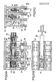
- FIG. 20a to 20c show a switching member 101 introduced into a groove 92 of a cover 91 for switching one of the plugs of the battery 33, associated with the cover 91, by rotation.
- FIG. 20a is a sectional view along the line XXA-XXA of FIG. 20c;
- Fig. 20b is a sectional view along the line XXB-XXB of FIG. 20a, the member 101 being drawn, but supposed to be transparent;
- Fig. 20c is a view in vertical section along the line XXC-XXC of FIG. 20a.
- the cylindrical parts 95 of the plugs 102 to 105 rest on the edges of the meshes of the grid 106 which supports the layer of wires 107.
- the grid 106 rests on a grid 108 which supports the layer of wires 109.
- the partitions 110 delimiting the grooves 92 of the cover 91 rest on the edges of the meshes of the grid 106 which are parallel to the wires 107.
- the width of a wall 110 is less than that of the bars of the grids, a vertical face of each partition falling practically vertically from the vertical face of the bar which is adjacent to the wire 107 and the other face of the partition falling substantially in the middle of the bar.
- the cylindrical parts 95 can rotate freely.
- the offset of each partition is explained by the fact that, in each mesh, the plug is also eccentric, as shown in FIG. 4.
- the height of the member 101 is practically equal to the distance between the plane delimited by the top of the cones 98 and the upper bottom of each groove 92.
- the width of the member 101 is equal to the internal width of the grooves 92.
- the member 101 consists of a central beam of cross-section at 1 111 and two flat control rods 112 and 113, arranged on each side of the core of the beam at 1 111.
- the sum of the thicknesses of the rods 112, 113 and the core of 111 is equal to that of the soles of I.
- the upper sole of the I bears against the bottom of the groove 92.
- the end 114 of the part 111 which is introduced into a groove 92 is bevelled so as to facilitate its introduction.
- the two sides of the lower sole 115 are cut over a certain length. Furthermore, above these cutouts, the core of 111 is drilled right through, and the opening 116 thus obtained serves as a cam groove for two studs 117 and 118 respectively fixed in the heads 119 and 120 of the ends rods 112 and 113.
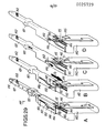
- the heads 119 and 120 respectively carry hooks 121 and 122 directed downwards and oriented so as to be able to exert a traction towards the entry of the groove 92.
- the heads 119 and 120 and the bodies of the rods are joined by parts 123 and 124 of reduced height compared to that of the body of the rods, which makes them flexible, so that the hooks 121 and 122 can be lowered on either side of the web of 111, where the sole 115 is cut.
- the light 116 has an S shape with the top 125 of the S towards the end 114 and the bottom 126 of the S towards the entrance of the groove, the bottom part 126 of the S also comprising a horizontal rectilinear race 127.
- the member 101 When it is desired to change the state of the plug 104 again, ie to rotate it clockwise, the member 101 is introduced into the corresponding groove 92 until the heads rods 112 and 113 slightly protrude from the head of 104. The rod 113 is then pulled, which has the effect of making the stud 118 describe the S of 116, the hook 122 then descends and meets the plane 100 which is driven until it escapes 122. We have the expected rotation.
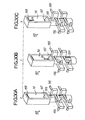
- Figs. 21a to 21c planes 99 and 100 make an angle such that the rotation of the plug is at each switching of + or - 90 °.
- the distance between the rods 112 and 113 is just greater than the diameter of the cylindrical bulge 97. Since the radius of 97 is practically half that of 95, the angle of the planes 99 and 100 is very little less than 180 °.
- the conical terminations 98 limit the surface in contact with the member 101 during translations of the latter in the groove and therefore limit the parasitic torques which would tend to rotate heads of unselected plugs.
- the rods 112 and 113 are held laterally, against the web of the beam 111, by two cheeks 128 and 129.
- the sum of the thicknesses of the cheeks 128 and 129 and the width of the sole of 111 is equal to the width a groove, up to the required clearance.
- FIG. 21a shows the plug head 104 at rest, as well as the rods 112 and 113 whose hooks 121 and 122 have been shown by hatched squares.
- Fig. 21b the rod 112 has been pulled and the hook 121 has driven the plane 98, so that the head has rotated by + 90 °.
- the width of the core of 111 is practically equal to the diameter of the central part 97 of the plug head. Therefore, when the rod 112 is pushed back to return to rest, the hook 121 can touch the lateral surface of 97, but does not cause the head to rotate.
- Fig. 21c the rod 113 has been pulled and, in a similar manner, rotates the head by - 90 °.
- the longitudinal position of the switching member in the groove must be such that the front part of the horizontal stroke 127 of 116 is slightly in front of the plane 98 while the rear part of 127 is found behind 99, or vice versa, depending on the orientation of the head. It is assumed that the member 101 is driven by a stepping motor whose pitch is equal to that of the plugs. Note that the cutouts in the soles of 115 have a length which can be less than twice the pitch of the cards and that they are practically centered on the card to be switched.
- Fig. 22 schematically shows a member 101 in front of the grooves 92 of a switching module 91.
- the arrow F2 suggests the first lateral movement to bring the member 101 in front of the selected groove and the arrow F3 suggests the longitudinal movement of the member in the groove to bring the cutouts of 115 above the head to switch.
- FIG. 23 there is shown a stack 33, surmounted by a cover 92, in which the sheets are all oriented with the head up, as indicated on the left part of the drawing. The pitch of the grooves is then equal to the pitch p of the sheets in their grids.
- FIG. 24 there is shown a stack 33 ′, surmounted by an upper cover 91 ′ and resting on a lower cover 91 ′′, in which the plugs are alternately oriented head up and head down, as indicated on the left side of the drawing
- the pitch of the grooves of the modules 91 ′ and 91 "is then equal to twice the pitch p of the plugs, ie equal to 2 p.
- the arrangement of FIG. 24 allows the use of heads 93 ′ of larger diameter, which has the advantage of doubling the active torque when the rods 112 and 113 of the switching members are actuated.
- Fig. 25 there is shown schematically in perspective a series of stacks of FIG. 9, mounted vertically.
- the batteries 130 are oriented so that their diagonals are aligned, leaving all on one side the installation area 131 and on the other side the operating area 132.
- an automaton 133 which can be moved on a rail 134 parallel to the bays 130, as indicated by the arrows F4.
- the bays 130 are provided with vertical rails or racks 135 making it possible to ensure the vertical displacement of the automaton 133 which carries a switching member 101, which can be moved laterally and longitudinally.
- the automaton 133 includes means for pulling and pushing the rods 112 and 113 of the member 101.
- the automaton 133 makes it possible to select the bay, to select the switching module 91 in the bay, the groove 92 in the module 91, to introduce the member 101 in the groove, to order the appropriate rod to make a connection or a disconnection, then to remove the member 101 from the groove. After an operation, the machine can return to the base of the bay. For all these operations, stepper motors can be provided in the PLC. It is clear that the positioning of a switching member can be fully automatic, as well as the operation of the rods 112 and 113. As a result, the switching operations inside the distributor can be fully automated, which has an important advantage. .
- Fig. 26 highlights the advantages of this type of battery.
- Two zones 131 and 132 are delimited, zone 131 being assigned to the line and installation teams and zone 132 being reserved for the operating service.
- the side 136 receives the conductors of the incoming cables 137 and the side 138 receives the conductors of outgoing cables 139 to the central office.
- Certain inter-battery connections can be made at the factory.
- the 140 side is assigned to the command and to the tests (link interruption, realization of bypass, etc.).
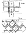
- Fig. 27 shows an example of a span consisting of two rows of back-to-back bays 130. This very compact arrangement requires the displacement (see arrow F5) of the stackable modules during the connections.
- Fig. 28 shows another example of a double row bay bay 130. This staggered arrangement allows direct access to the incoming 137 and outgoing 139 cables.
- Figs. 29a to 29d schematically represent a manual intervention tool 141 which makes it possible to actuate the plug heads like a member 101.
- the tool 141 comprises a member 101 mounted, in the manner of a pistol barrel, on a stock 142.
- the external ends of the rods 112 and 113 are subjected to the action of compressed springs 143 and 144 which tend to repel them. towards the end 116.
- the stock 142 is provided with a trigger 145 which makes it possible to push a lever towards the rear of the tool, as indicated by arrow F6.
- a slide 146 is mounted astride the rear part of 101.
- the slide 146 has a slot 147 open upwards in the shape of an S.
- the center of the S is perpendicular to the median plane of the rods 112 and 113
- the ends of the S are straight and parallel to the axis of 101, one 148 above 112 and the other 149 above 113.
- the lever 150 secured to the trigger 145 has its upper end which passes in the slot 147. When the slider 146 is pushed forward, the end of the lever 150 is offset towards the rod 112. When in these conditions, the trigger 145 is pressed, the lever 150 abuts the curved part (towards 113) of the rod 112 so that the rod 112 is pulled out and can actuate a plug head as has been described in relation to FIGS. 20a to 20c.
- FIG. 17a shows the pistol 97 in the rest state, the slide 107 being positioned correctly so that the heads 75 and 76, symbolically represented by a square 108, can be, once the member is pressed, above the head to switch.
- Fig. 29b shows the position of the slide 146 for carrying out a connection operation, the trigger 145 being able to pull the rod 112.
- Fig. 29c shows the position of the slide 146, pulled back, to prepare a disconnection operation.
- Fig. 29d shows the action of the trigger 145 on the lever 150 which drives the rod 113 for a disconnection operation.
- Figs. 30a to 30c show a variant of the plug 88 of FIG. 18 in three different states: at rest, when passing into the working position and when passing into the rest position.
- Sheet 153 of Figs. 30a to 30c is distinguished from the plug 88 by the shape of its contact 154 which is not circular, but in inverted L, the leg of the L ensuring electrical continuity with the wire 155 of a first ply and the base of the L ensuring electrical continuity with wire 156 of the second perpendicular layer.
- the plug 153 is provided with as many contacts 154 as there are crossing points to close.
- the head 90 of the plug 153 has the shape of a vertical rectangular frame whose long sides are parallel to the axis of the plug and whose vertical axis of symmetry corresponds to the axis of the plug.
- the short sides 157 and 158 of the head 90 have a cross section having a convex rounded inwardly of the frame.
- the surface defined by each rounding serving as a contact surface with a finger of a switching member.
- Fig. 31a the plug 153 is at rest, that is to say in the high position.
- Contact 154 is in contact with high wire 155, but not with low wire 156.
- the crossover point is not closed.
- a finger symbolized by the arrow F8, pushes the boss of 157 down so that the plug is lowered and the contact 154 comes into contact with the low wire 156, while remaining in contact with the high wire 155 The crossing point closes.
- a switching member capable of actuating the plugs 153 cooperate with stacks of grids identical to the stack 33, which are associated with control modules 159, similar to the module 91.
- the height of the module 159 is greater than that of the module 91 to allow the housing of the heads 90, on the one hand, higher than the heads 93 of the rotary plugs, and, on the other hand, driven in translational movement vertical, as just described in relation to Figs. 30a to 30c.
- the control module 159 has the form of a cover formed by juxtaposed grooves 160 which serve as guide elements for a switching member 161 whose general shape is similar to that of member 101.
- the grooves 160 are delimited by partitions 162.
- Each partition 162 carries a first series of shims 163 arranged, at the bottom, on one side of the partition and a second series of shims 164 disposed at the very top of the partition.
- each groove 160 has a series of shims 164, above and to the left, looking at FIG. 31c, and a series of wedges 163, bottom and right.
- the shims are arranged in pairs, each pair comprising a shim 163 and a shim 164 which are in the same vertical plane which coincides with that of a grid bar of the stack.
- the pairs of shims are arranged with the same pitch as the plugs 163.
- the vertical distance between the upper edge of a shim 163 and the lower edge of the shim 164 of the same pair is equal to the required clearance, at the height of the switching member 161.
- the partitions 162 have the same relative position, with respect to the bars of the grids, as the partitions 110, FIG. 20c.
- the member 151 consists of a hollow rectangular section beam comprising two vertical cheeks 165 and 166, and two horizontal plates 167 and 168. In the hollow part, between the cheeks 165 and 166, are mounted two flat rods 169 and 170 .
- the width of the member 161 equal to the distance between the external faces of the cheeks 165 and 166, is equal, apart from the necessary clearance, to the internal width of the frame of the head 90 of the plug 153.
- the height of the member equal to the distance between the end faces of the plates 167 and 168, is less than the distance between the bosses 157 and 158.
- the end 171 of the member 151 which is introduced into a groove 150, is bevelled.
- the plate 167 has a lumen 172, substantially opposite the rod 169 and the plate 168 has a lumen 173, substantially opposite the rod 170.
- the head 174 of the rod 169 has a part 175 connected at 90 ° to the rod 170.
- a flexible part 176 is provided, the height of which is reduced.
- the head 177 of the rod 170 has a part 178 folded back towards the rod 169. Between the head 177 and the body of the rod 170, a flexible part 179 is provided.
- the cheek 165 has a very open V-shaped light 180, of which a high horizontal branch is directed towards the end 171 and whose downwardly inclined branch ends just above the light 172.
- the head 174 of rod 169 is provided with a pin 181 which is introduced into the slot 180.
- the pin 181 is in the upper part of the slot 180 so that the head 174 is high and that the folded part 175 is entirely inside the profile of the member 168.
- the pin 181 descends into the light 180 and, as shown in FIG. 31a, pushes the boss 157 of a plug 153 downwards.
- the light 180 has a shape such that the stroke of the part 175, which serves as a pusher, causes the head 90 to descend until it comes into contact with the upper surface of the underlying grid 106. Once the plug has been lowered, the rod 169 is pushed forward, the lug 181 rises, driving the head 174, but the plug head 90 remains in the low position.
- the cheek 166 has a very open V-shaped lumen 182, which is symmetrical with the lumen 180 relative to the horizontal axis of symmetry of the member 151, and the head 177 of the rod 170 is provided with a post 183 engaged in the slot 182.
- 182 is symmetrical with 180, when the rod 170 is pushed towards the end 171, the post 183 is in the lower part of the slot 182 so that the head 177 is low and that the folded part 178 is entirely inside the profile of 151.
- the lug 183 rises in the slot 182 and pushes the boss 158 upwards.
- the pin 183 has reached its highest point, the head 90 is practically applied against the bottom of the module 149.
- the members 151 can be actuated exactly like the members 101, since it suffices to position them correctly in the longitudinal direction, then to pull one or the other of the control rods.
- the member 151 can also be mounted on a gun, such as that described in relation to Figs. 29a to 29d.
- Fig. 32 there is shown a stack 33, surmounted by a module 149, in which the cards are all oriented with the head up, as indicated on the left part of the drawing.
- These files function as we have just described in relation to Figs. 29a to 29b.
- two batteries 184 and 185 have been shown which are symmetrical to each other and between which a control module 186 is sandwiched.
- the battery 184 may be identical to a battery 33.
- the plugs 187 used in this assembly are consist of two contact-carrying rods mounted symmetrically on each side of a head 90. Use is made in module 186 of switching members 151. The operation of such an assembly, with plugs 187, is obvious to a person of art. This arrangement is of interest when the number of contacts per crossing point is large.
Landscapes
- Engineering & Computer Science (AREA)
- Power Engineering (AREA)
- Computer Networks & Wireless Communication (AREA)
- Structure Of Telephone Exchanges (AREA)
- Push-Button Switches (AREA)
Applications Claiming Priority (4)
| Application Number | Priority Date | Filing Date | Title |
|---|---|---|---|
| FR7921202 | 1979-08-16 | ||
| FR7921202A FR2468990A1 (fr) | 1979-08-16 | 1979-08-16 | Commutateur a plusieurs couches de points de croisement |
| FR8008934 | 1980-04-15 | ||
| FR8008934A FR2480494A2 (fr) | 1980-04-15 | 1980-04-15 | Commutateur a plusieurs couches de points de croisement |
Publications (2)
| Publication Number | Publication Date |
|---|---|
| EP0025729A1 true EP0025729A1 (de) | 1981-03-25 |
| EP0025729B1 EP0025729B1 (de) | 1984-12-27 |
Family
ID=26221327
Family Applications (1)
| Application Number | Title | Priority Date | Filing Date |
|---|---|---|---|
| EP19800401188 Expired EP0025729B1 (de) | 1979-08-16 | 1980-08-13 | Schalter mit mehreren Lagen von Kreuzungspunkten |
Country Status (3)
| Country | Link |
|---|---|
| EP (1) | EP0025729B1 (de) |
| CA (1) | CA1159977A (de) |
| DE (1) | DE3069866D1 (de) |
Cited By (2)
| Publication number | Priority date | Publication date | Assignee | Title |
|---|---|---|---|---|
| EP0038256B1 (de) * | 1980-04-15 | 1985-04-03 | ETAT FRANCAIS repr. par le Secrétaire d'Etat aux Postes et Télécomm. et à la Télédiffusion (CENT. NAT. D'ETUDES DES TELECOMM.) | Schalter mit mehreren Lagen von Kreuzungspunkten |
| CN115896899A (zh) * | 2022-11-04 | 2023-04-04 | 宁波韵升股份有限公司 | 一种钕铁硼磁钢磷化自动挂镀工艺 |
Citations (6)
| Publication number | Priority date | Publication date | Assignee | Title |
|---|---|---|---|---|
| FR1457726A (fr) * | 1964-10-02 | 1966-01-24 | Matrice d'interconnexion | |
| US3312792A (en) * | 1966-01-28 | 1967-04-04 | Gen Dynamics Corp | Matrix switch with improved contact actuator means |
| FR1584604A (de) * | 1968-07-26 | 1969-12-26 | ||
| GB1196111A (en) * | 1966-05-12 | 1970-06-24 | Gen Electric & English Elect | Improvements in or relating to Cross-bar Selector Switches |
| FR2038444A6 (de) * | 1969-03-07 | 1971-01-08 | Lucas Pierre | |
| US4125309A (en) * | 1977-06-22 | 1978-11-14 | Amp Incorporated | Miniature pin board assembly |
-
1980
- 1980-08-12 CA CA000358076A patent/CA1159977A/en not_active Expired
- 1980-08-13 EP EP19800401188 patent/EP0025729B1/de not_active Expired
- 1980-08-13 DE DE8080401188T patent/DE3069866D1/de not_active Expired
Patent Citations (6)
| Publication number | Priority date | Publication date | Assignee | Title |
|---|---|---|---|---|
| FR1457726A (fr) * | 1964-10-02 | 1966-01-24 | Matrice d'interconnexion | |
| US3312792A (en) * | 1966-01-28 | 1967-04-04 | Gen Dynamics Corp | Matrix switch with improved contact actuator means |
| GB1196111A (en) * | 1966-05-12 | 1970-06-24 | Gen Electric & English Elect | Improvements in or relating to Cross-bar Selector Switches |
| FR1584604A (de) * | 1968-07-26 | 1969-12-26 | ||
| FR2038444A6 (de) * | 1969-03-07 | 1971-01-08 | Lucas Pierre | |
| US4125309A (en) * | 1977-06-22 | 1978-11-14 | Amp Incorporated | Miniature pin board assembly |
Cited By (2)
| Publication number | Priority date | Publication date | Assignee | Title |
|---|---|---|---|---|
| EP0038256B1 (de) * | 1980-04-15 | 1985-04-03 | ETAT FRANCAIS repr. par le Secrétaire d'Etat aux Postes et Télécomm. et à la Télédiffusion (CENT. NAT. D'ETUDES DES TELECOMM.) | Schalter mit mehreren Lagen von Kreuzungspunkten |
| CN115896899A (zh) * | 2022-11-04 | 2023-04-04 | 宁波韵升股份有限公司 | 一种钕铁硼磁钢磷化自动挂镀工艺 |
Also Published As
| Publication number | Publication date |
|---|---|
| DE3069866D1 (en) | 1985-02-07 |
| CA1159977A (en) | 1984-01-03 |
| EP0025729B1 (de) | 1984-12-27 |
Similar Documents
| Publication | Publication Date | Title |
|---|---|---|
| EP0403350B1 (de) | Verfahren und Vorrichtung für die Herstellung von Kabelbäumen | |
| FR2530082A1 (fr) | Procede et appareil d'assemblage des composants d'une batterie d'accumulateurs | |
| FR2464616A1 (fr) | Dispositif et procede de montage de composants electriques sur des platines | |
| BE897637A (fr) | Dispositif et procede de positionnement de lames et d'ailettes pour des grilles de support de barres de combustible nucleaire | |
| EP0108700A1 (de) | Fachbildungsvorrichtung mit Nadelwahl | |
| BE1004176A3 (fr) | Dispositif de transfert pour supports d'informations. | |
| EP0025729B1 (de) | Schalter mit mehreren Lagen von Kreuzungspunkten | |
| BE897642A (fr) | Grille a barreaux combustibles avec des manchons soudes dans des bandes encochees | |
| EP0081795B1 (de) | Elektrischer Verbinder mit mehrfacher Kupplung und Verwendung desselben in mehrfachen Messverbindern für Schaltungsplatte von einem in einem Rahmen montierten elektronischen Gerät | |
| FR2480494A2 (fr) | Commutateur a plusieurs couches de points de croisement | |
| FR2846481A1 (fr) | Procede et dispositif d'insertion d'un enroulement dans un stator, avec stratification du chignon | |
| BE1005699A3 (fr) | Equipement d'assemblage de jeu de combustible nucleaire. | |
| US4421965A (en) | Commutator with several layers of cross-points | |
| EP0038256B1 (de) | Schalter mit mehreren Lagen von Kreuzungspunkten | |
| FR2634982A1 (fr) | Machine a confectionner des brochettes | |
| WO2002082587A1 (fr) | Connecteur pour montage en surface de circuit imprime et procede de fabrication | |
| FR2886504A1 (fr) | Dispositif d'interconnexion reconfigurable de faisceaux electriques | |
| BE1007101A3 (fr) | Equipement destine a attacher un element de clavette a une grille d'assemblage de combustible nucleaire et a l'en detacher. | |
| FR2480495A2 (fr) | Commutateur a plusieurs couches de points de croisement | |
| EP0489642B1 (de) | Vorverdrahtbare Anschlussleiste | |
| BE347769A (de) | ||
| FR2496975A2 (fr) | Commutateur a plusieurs couches de points de croisement | |
| BE436303A (de) | ||
| EP0664073B1 (de) | Verfahren zur herstellung einer leitenden schaltung | |
| FR3102077A1 (fr) | Dispositif d'alimentation en plaques d'une machine de decoupe a partir d'un magasin. |
Legal Events
| Date | Code | Title | Description |
|---|---|---|---|
| PUAI | Public reference made under article 153(3) epc to a published international application that has entered the european phase |
Free format text: ORIGINAL CODE: 0009012 |
|
| AK | Designated contracting states |
Designated state(s): BE CH DE GB IT NL SE |
|
| 17P | Request for examination filed |
Effective date: 19810923 |
|
| ITF | It: translation for a ep patent filed | ||
| GRAA | (expected) grant |
Free format text: ORIGINAL CODE: 0009210 |
|
| AK | Designated contracting states |
Designated state(s): BE CH DE GB IT LI NL SE |
|
| REF | Corresponds to: |
Ref document number: 3069866 Country of ref document: DE Date of ref document: 19850207 |
|
| PGFP | Annual fee paid to national office [announced via postgrant information from national office to epo] |
Ref country code: NL Payment date: 19850831 Year of fee payment: 6 |
|
| PLBE | No opposition filed within time limit |
Free format text: ORIGINAL CODE: 0009261 |
|
| STAA | Information on the status of an ep patent application or granted ep patent |
Free format text: STATUS: NO OPPOSITION FILED WITHIN TIME LIMIT |
|
| 26N | No opposition filed | ||
| PG25 | Lapsed in a contracting state [announced via postgrant information from national office to epo] |
Ref country code: SE Effective date: 19860814 |
|
| PG25 | Lapsed in a contracting state [announced via postgrant information from national office to epo] |
Ref country code: LI Effective date: 19860831 Ref country code: CH Effective date: 19860831 |
|
| BERE | Be: lapsed |
Owner name: L' ETAT FRANCAIS REPRESENTE PAR LE SECRETAIRE D'ET Effective date: 19860831 |
|
| PG25 | Lapsed in a contracting state [announced via postgrant information from national office to epo] |
Ref country code: NL Effective date: 19870301 |
|
| NLV4 | Nl: lapsed or anulled due to non-payment of the annual fee | ||
| GBPC | Gb: european patent ceased through non-payment of renewal fee | ||
| REG | Reference to a national code |
Ref country code: CH Ref legal event code: PL |
|
| PG25 | Lapsed in a contracting state [announced via postgrant information from national office to epo] |
Ref country code: DE Effective date: 19870501 |
|
| PG25 | Lapsed in a contracting state [announced via postgrant information from national office to epo] |
Ref country code: GB Effective date: 19881118 |
|
| PG25 | Lapsed in a contracting state [announced via postgrant information from national office to epo] |
Ref country code: BE Effective date: 19890831 |
|
| EUG | Se: european patent has lapsed |
Ref document number: 80401188.0 Effective date: 19870812 |