EP0026113A1 - Machines textiles de traitement de fil et procédé pour réduire les pertes en matière textile sur de telles machines - Google Patents
Machines textiles de traitement de fil et procédé pour réduire les pertes en matière textile sur de telles machines Download PDFInfo
- Publication number
- EP0026113A1 EP0026113A1 EP80303361A EP80303361A EP0026113A1 EP 0026113 A1 EP0026113 A1 EP 0026113A1 EP 80303361 A EP80303361 A EP 80303361A EP 80303361 A EP80303361 A EP 80303361A EP 0026113 A1 EP0026113 A1 EP 0026113A1
- Authority
- EP
- European Patent Office
- Prior art keywords
- detector
- air
- strand
- yarn processing
- sensing
- Prior art date
- Legal status (The legal status is an assumption and is not a legal conclusion. Google has not performed a legal analysis and makes no representation as to the accuracy of the status listed.)
- Granted
Links
- 238000000034 method Methods 0.000 title claims abstract description 11
- 239000002699 waste material Substances 0.000 title claims abstract description 11
- 239000004753 textile Substances 0.000 title claims description 31
- 238000012544 monitoring process Methods 0.000 claims description 12
- 238000009987 spinning Methods 0.000 claims description 11
- 230000001939 inductive effect Effects 0.000 claims description 8
- 238000004140 cleaning Methods 0.000 claims description 7
- 230000000452 restraining effect Effects 0.000 claims description 4
- 238000001514 detection method Methods 0.000 description 15
- 241001589086 Bellapiscis medius Species 0.000 description 5
- 230000002238 attenuated effect Effects 0.000 description 5
- 238000007664 blowing Methods 0.000 description 5
- 239000000463 material Substances 0.000 description 3
- 238000010276 construction Methods 0.000 description 2
- 230000001771 impaired effect Effects 0.000 description 2
- 238000004519 manufacturing process Methods 0.000 description 2
- 238000007383 open-end spinning Methods 0.000 description 2
- 230000015572 biosynthetic process Effects 0.000 description 1
- 230000000903 blocking effect Effects 0.000 description 1
- 230000015556 catabolic process Effects 0.000 description 1
- 238000006731 degradation reaction Methods 0.000 description 1
- 238000009434 installation Methods 0.000 description 1
- 239000000725 suspension Substances 0.000 description 1
Images

Classifications
-
- D—TEXTILES; PAPER
- D01—NATURAL OR MAN-MADE THREADS OR FIBRES; SPINNING
- D01H—SPINNING OR TWISTING
- D01H13/00—Other common constructional features, details or accessories
- D01H13/14—Warning or safety devices, e.g. automatic fault detectors, stop motions ; Monitoring the entanglement of slivers in drafting arrangements
- D01H13/145—Warning or safety devices, e.g. automatic fault detectors, stop motions ; Monitoring the entanglement of slivers in drafting arrangements set on carriages travelling along the machines; Warning or safety devices pulled along the working unit by a band or the like
Definitions
- This invention relates to traveling ends-down tending systems for textile strand or yarn processing machines, such as spinning frames, twisters and the like, and more particularly, to an improved apparatus and method for monitoring a row or series of yarn processing units alternately in a forward or first direction and in an opposite, rearward or second direction during which the absence or breakage of any strand issuing from a processing unit is detected, and in response to such detection, a corresponding supply strand passing into the processing unit is interrupted.
- textile strands are spun on conventional or open-end spinning machines.
- spun strands and/ or continuous filament strands are intertwisted on twisting machines.
- supply strands are directed from supply sources into a row or series of processing units, and the processed strands are delivered to respective take-up means.
- the supply strands are generally in the form of rovings, and the processing units are in the form of drafting units.
- the supply strands are generally in the form of slivers and the processing units generally are in the form of rotor units.
- twisters the supply strands are generally in the 'form of spun yarns and the processing units are in the form of twister rolls or twister heads.
- That patent discloses the use of a traveling pneumatic cleaner serving as a carrier or carriage for a travelling detector means which monitors a series of processed strands issuing from a series of yarn processing units, such as drafting units, to which respective supply strands pass.
- the respective supply strand is interrupted by direction of flowing air from the traveling cleaner to impinge upon and actuate a respective strand interrupting member by displacing the same from a normal or inactive position to an active position such as to engagingly restrain and thus interrupt movement of the respective supply strand into the processing unit.
- the detector means is positioned so as to lead the projected flow path or "air bullet" of the directed air flow in accordance with the direction of travel of the traveling cleaner, thus providing a minimal response time for effecting the direction of the flowing air upon detection of a broken processed strand,, such response time serving to insure that the "air bullet" will impinge on only the properly selected one of the strand interrupting means.
- the traveling pneumatic cleaners are constructed so that they may move alternatively in either direction, that is, the traveling cleaner may alternately traverse a textile yarn forming machine or a row or rows of such machines in opposite directions, such as in the instance of the traveling cleaner being mounted to travel on a double- ended track, or in the event that a particular machine or a portion thereof is being repaired by persons whose efficiency might be impaired by the movement of the traveling cleaner past such persons while they are repairing the machine. Since the detector means on the traveling pneumatic cleaner leads the "air bullet" in the aforementioned patent, it can be appreciated that the timing relation between the detector means and the "air bullet" would be reversed if the direction of travel of the traveling cleaner were to be reversed.
- the detection of a broken processed strand by the traversing detector means would occur after the projected path of the directed air flow or "air bullet"' had already moved past the supply strand interrupting means which must be actuated for interrupting the desired proper supply strand, and thus the latter supply strand would not be interrupted and a lap-up likely would occur. Also, because of the usual narrow gauge . or relatively close proximity of adjacent processing units of yarn processing machines, the directed air flow or "air bullet” might impinge upon and actuate other than the desired strand interrupting member and thus cause unintentional interruption of a supply strand into a processing unit whose processed strand issuing therefrom has not been broken.
- An object of the present invention is further to facilitate improved efficiency in the production of textile yarn by providing an improved method and apparatus for monitoring and detecting breakage of processed strands during both forward and rearward movement of a detecting means, in alternation, past a corresponding series of yarn processing units.
- the present invention consists in a method of reducing waste of supply strands passing to a plurality of yarn processing units, such as drafting units, arranged in a series along a textile yarn processing machine, such as a yarn spinning machine, upon breakage of corresponding strands being delivered from the yarn processing units, characterised by the steps of:
- the invention consists in a textile yarn processing machine, such as a yarn spinning machine having a plurality of yarn processing units, such as drafting units, arranged in a series along the yarn machine, and apparatus for reducing waste of supply strands passing to the yarn processing units upon breakage of corresponding strands being delivered from the yarn processing units, characterised by:
- the invention consists in a textile yarn processing machine, such as a yarn spinning machine, having a plurality of yarn processing units, such as drafting units, arranged in a series along the yarn processing machine, and apparatus for reducing waste of supply strands passing to the yarn processing units upon breakage of corresponding strands being delivered from the yarn processing units, characterised by
- apparatus which traverses detector means along textile yarn processing machines, such as spinning frames, twisters and the like, for monitoring and detecting the absence or breakage of strands issuing from processing units, and in response to such detection, interrupting a corresponding supply strand passing into the respective processing unit.
- the present invention is particularly concerned with apparatus in which the traversing of detector means is effected by a traveling pneumatic cleaner generally indicated at 10 mounted on a track generally indicated at 11 for movement above and along a plurality of yarn processing units or spindles on at least one textile strand processing machine embodied in a spinning frame generally designated at 12.
- the traveling pneumatic cleaner 10 may be substantially identical to the fourth embodiment disclosed in United States Patent No. 3,304,571, issued on February 21, 1967, and may be equipped with a reversing mechanism of the general type disclosed in United States Patent No. 3,011,204, issued on December 5, 1961.
- the traveling cleaner is supported for movement along track 11 which extends above the yarn processing machine 12, and as .further disclosed in the latter patent, the traveling cleaner 10 includes drive means for driving it in movement along the track so as to traverse one or more yarn forming or processing machines 12 automatically in a first or forward direction, and alternately, in a second, opposite or rearward direction. While a particular form of traveling pneumatic cleaner is described herein, it is to be understood that this choice has been made for purposes of illustration only.
- the present invention contemplates that the traveling unit of this invention or the manner in which the unit is supported and arranged for traversing a textile machine or machines may be changed in varying ways, including limitation of the path of travel of a unit to traverse a single machine only and/or to reverse its direction of movement in the course of traversing a single machine, such as in the instance that a particular machine or a portion thereof is being repaired by persons whose efficiency might be impaired by the movement of the traveling cleaner past such persons while they are repairing the machine.
- the traveling pneumatic cleaner 10 includes a fan impeller 15 and a fan drive motor (not shown) for driving the fan impeller in rotation.
- Fan impeller 15 is enclosed within an air flow housing 16 which, in the preferred embodiment as illustrated, is divided into a suction air flow portion and a blowing air flow portion.
- the blowing air flow portion of the fan housing 16 delivers flowing air through blowing sleeves 17 for the air flow to be directed against portions of the textile machine 12 for cleaning the same.
- the traveling cleaner 10 has four depending sleeves including two blowing cleaning sleeves 17 and two suction cleaning sleeves 18. As so arranged, the traveling cleaner 10 services both sides of the textile machine 12 during each traverse thereof in each direction.
- the textile yarn processing machine 12 includes a plurality of yarn processing units D which are shown in the form of drafting units arranged in series along the machine.
- each drafting unit D includes an arrangement of paired rolls 30, 31, 32 through which textile material passes to be drafted or attenuated.
- Each drafting unit normally receives at least one corresponding supply strand or roving R.
- the supply strands or . rovings R are led from respective packages 34 downwardly to be passed through respective trumpets 35 and thus introduced into a nip defined between the back drafting rolls 30.
- the textile material is delivered from the front rolls 32 as a processed or attenuated strand S. Since a spinning frame is illustrated in Figure 1, it is apparent that the strand S being delivered from each yarn processing unit has twist inserted therein in a generally known manner in order to form the yarn which is wound on spindle-supported bobbins or spools B.
- a plurality bf roving feed stop members or strand interrupting members each of which is generally designated at 38, and which correspond in number to the number of yarn processing units D, with each of the strand interrupting members 38 being mounted on the yarn processing machine 12 adjacent a corresponding one of the yarn processing units D.
- the strand interrupting members 38 are mounted for independent pivoting movement between a first position withdrawn from the corresponding supply strand R (as shown in Figures 1 and 4) and a second position intersecting the supply strand.
- the strand interrupting members 38 may be of any desired construction for performing the intended purpose and-are shown as being of a type such as is disclosed in U.S. Patent No. 4,000,603, issued January 4, 1977, to which reference is made for a more detailed description thereof.
- each strand interrupting member 38 may take the form of a plug 41 of generally truncated conical configuration and cooperating with a stationary ring means or torus 42, with the plug 41 being sized for occluding the corresponding torus 42 for engagingly restraining passage of the corresponding supply strand R therethrough in its course to the corresponding yarn processing unit D.
- Each plug is suitably secured to one end portion of a corresponding pivoting member 43 supported from a mounting bracket 44 for pivotal movement about an axis spaced above and outwardly of the corresponding yarn processing unit D.
- Each pivoting member 43 is balanced relative to its pivot point so that it normally occupies the inactive position shown in Figure 4 with the corresponding plug-41 occupying a withdrawn or raised position with respect to the corresponding ring or torus 42.
- each pivoting member 43 having the plug 41 thereon is provided with an air impingement surface 45 which faces forwardly or butwardly with respect to the corresponding yarn processing unit D and is adapted to be impinged upon by an airstream, in a manner to be later described, for tilting the respective pivoting member 43 so that its plug 41 is moved into the corresponding torus 42 for grippingly engaging and entrapping a corresponding supply strand between the plug and the ring 42.
- the corresponding supply strand R will be interrupted in its passage to the respective yarn processing unit.
- the strand interrupting members 38 are pivoted between a first position withdrawn from the corresponding supply strand, as shown in Figure 4, and a second position in which they engagingly restrain the respective supply strand.
- the strand interrupting members 38 are actuated to the second or active position in response to the sensing of the breakage of any one of the series of strands S being delivered from the yarn processing units by moving a detector along the processing machine alternately in a first direction and in a second direction opposite from the first direction to thus monitor the condition of the series of strands being delivered, and in response to the sensing of the breakage of any of the strands and irrespective of the direction of movement of the detector, the passage of the corresponding supply strand S to its yarn processing unit is interrupted by directing a flowing stream of air from a nozzle moving with the detector into engagement with a corresponding strand interrupting member 38.
- a portion of the air flow being induced by the fan impeller 15 of the traveling pneumatic cleaner 10 is directed from the traveling pneumatic cleaner 10 and into engagement with the corresponding strand interrupting member under control bf monitoring means including a detector moving with the traveling cleaner 10 along the series of yarn processing units-D for detecting breakage of the processed strands S being delivered from the yarn processing units.
- the monitoring means includes a detector head 50 depending from the traveling cleaner 10 so as to be disposed between the blowing and suction sleeves 17, 18 ( Figure 1).
- suspension of the detector head 50 is accomplished by means of a depending elongate mounting member or duct 51.
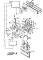
- a suitable detection device shown in the form of a photoelectric detector 52 and a lamp 53 mounted in the lower portion of the detector head 50 in Figure 4, is operatively connected with suitable circuitry for distinguishing between the presence and absence of attenuated or processed strands S as the monitoring means moves along the series of yarn processing units D.
- suitable circuitry for distinguishing between the presence and absence of attenuated or processed strands S as the monitoring means moves along the series of yarn processing units D.
- the monitoring means of the present invention embodied in the detector 52 and lamp 53 of Figures 2 and 4, has a particular predetermined field of view indicated generally at 55 within which processed strands S issuing from the yarn processing units D are viewed. During movement of the monitoring means along the series of yarn processing units, the corresponding series of processed strands S are thus monitored in succession.
- air flow directing means is mounted for movement with the traveling cleaner 10 and is related to the monitoring means in a particular predetermined manner for assuring that a selected one strand interrupting means corresponding to the yarn processing unit at which a processed strand might be broken is actuated, irrespective of the direction of movement of the monitoring means.
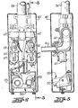
- the air flow directing means is largely positioned within and carried by a housing 60 within the lower portion of which the detector head 50 is also conveniently positioned.
- the air flow directing means comprises a pair of first and second elongate outlet nozzles 61, 61' whose outlet ends are directed toward the textile machine or yarn processing machine 12.
- the nozzles 61, 61' are spaced above and astraddle the vertical plane of the field of view of the photoelectric detector 52 so that,whenever an airstream or "air bullet" flows from the first nozzle 61, which may occur only during movement of the traveling cleaner in a first or forward direction; that is, from right to left in Figure 2 and from left to right in Figure 4, there will be a slight trailing relation between the direction of the "air bullet” thus released and the field of view of the detection means or detector 52 (in the direction of movement of the traveling cleaner 10).
- the outer ends of the nozzles 61, 61' that is the ends of the nozzles 61, 61 remote from the textile machine 12, are connected, via respective valve means, to branch ducts or pipe elbows 62, 62' which extend upwardly and are communicatively connected to the lower end of the depending member or conduit 51.
- the upper end of the conduit 51 communicates with the outlet side of the fan housing 16 by means of a corresponding flexible conduit 63 ( Figure 1).
- the valve means associated with the air flow nozzles 61, 61' comprises a pair of respective elongate flap valve members 65, 65' which are normally biased to closed positions blocking the outlet ends of the respective pipe fittings or pipe elbows 62, 62' to prevent the flow of air therefrom outwardly through the respective nozzles 61, 61'.
- the flap valve members 65, 65' extend downwardly through suitable openings between the respective pipe fittings or elbows 62, 62' and the nozzles 61, 61'.
- the flap valve members 65, 65' are mounted on the output shafts of respective rotary solenoids 67, 67' serving as respective electromagnet ⁇ c means for operating the valve members 65, 65'.
- the solenoids 67, 67' are suitably supported in the housing 60 and are electrically connected to respective "And" gates 71, 71'. Corresponding sides of the "And" gates 71, 71' are connected to a common end detection circuit 72 to which the photoelectric detector 52 is electrically connected.
- the end detection circuit 72 may be of the type such as is shown in Figure 11 of U.S. Patent No. 3,523,413 or Figure 7 of U.S. Patent No. 3,659,409. Accordingly, a further description of the end detection circuit is deemed unnecessary. However, to the extent that the disclosures of U.S. Patents Nos. 3,523,413 and 3,659,409 may be required for the purpose of fully understanding the disclosure herein made, these latter prior patent disclosures are hereby incorporated by reference into this disclosure.
- the direction sensing gates have respective direction sensing elements or cells 74, 74' electrically connected thereto which produce signals in the direction sensing gates 73 in accordance with the direction of rotation of a so-called tachometer 75 which rotates with one or more of the track engaging wheels of the traveling pneumatic cleaner 10, thus reflecting the direction of travel of the traveling cleaner 10 along the track 11.
- the construction and operation of direction sensing gates such as are indicated at 73 in Figure 4 are well known to those familiar with the art of electrical circuitry and from prior patents and trade publications. Accordingly, a detailed description and illustration thereof is deemed unnecessary.
- the sensing element 74 signals the direction sensing gates 73 and thus the "And" gate 71 is actuated to "ready,” the solenoid 67 for energization thereof upon the detector 52 sensing breakage of any one of the series of strands S being delivered from the yarn processing units during movement of the traveling cleaner in the first or forward direction.
- the solenoid 67 will be actuated in ' response to the sensed breakage of the corresponding strand S and the flap valve member 65 will then be moved to open position to permit a rush of air or "air bullet" to flow out of the then trailing nozzle 61 and to impinge against the respective strand interrupting member 38 and thereby move such strand interrupting member to the active position for engagingly restraining the corresponding roving or supply strand R, thus interrupting the same in its course to the corresponding yarn processing unit and thus preventing any substantial amount of the supply yarn from being drawn into the corresponding vacuum end collection nozzle 36 ( Figure 1), to be drawn into the waste collection chamber as heretofore described.
- the interval of time within which the air flow through either air discharge nozzle 61, 61' must be started and stopped to actuate one roving stop . member or strand interrupting member 38 is about 1/5 second.
- the first and second nozzles 61, 61' are so located relative to detector 52 that the line of flow of air or "air bullet" whenever discharged from either nozzle, is between the normal paths of supply strands S being received by adjacent yarn processing units D.
- such lines of flow of the air from the first and second nozzles 61, 61' trail behind the detector 52 during movements thereof in the aforementioned respective first and second directions. Accordingly, as described in the last-mentioned U.S. Patents Nos.
- time delay means (not shown) is included in and operably associated with the end detection circuit 72 ( Figure 4) for delaying the opening of each first and second nozzle 61, 61' upon the detector means or detector 52 sensing breakage of a processed strand S so that the line of flow of air from each nozzle will pass a preceding unbroken supply strand R before the corresponding airstream or "air bullet" is discharged from the respective nozzle and in accordance with the direction of movement of the detector means, or stated otherwise, until such nozzle is properly aimed with respect to the appropriate strand interrupting member.
- the tachometer 75 has been described as a preferred means for sensing the direction of movement of the traveling cleaner 10, it is apparent that the usual plunger means for changing the direction of movement of the traveling cleaner, such as that disclosed in said U.S. Patent No. 3,011,204, may be employed for actuating a suitable switch or the like for effecting the proper operation of the direction sensing gates 73 and the "And gates 71, 71 1 to assure that the valve means for the "trailing" nozzle is that one which is opened in response to the sensing of the breakage of any one of the series of strands being delivered from the yarn processing units by the detector 52, irrespective of the direction of movement of the detector.
Landscapes
- Engineering & Computer Science (AREA)
- Mechanical Engineering (AREA)
- Textile Engineering (AREA)
- Spinning Or Twisting Of Yarns (AREA)
Applications Claiming Priority (2)
| Application Number | Priority Date | Filing Date | Title |
|---|---|---|---|
| US06/077,932 US4263776A (en) | 1979-09-24 | 1979-09-24 | Apparatus and method for interrupting textile yarn processing operations |
| US77932 | 1979-09-24 |
Publications (2)
| Publication Number | Publication Date |
|---|---|
| EP0026113A1 true EP0026113A1 (fr) | 1981-04-01 |
| EP0026113B1 EP0026113B1 (fr) | 1985-01-09 |
Family
ID=22140871
Family Applications (1)
| Application Number | Title | Priority Date | Filing Date |
|---|---|---|---|
| EP80303361A Expired EP0026113B1 (fr) | 1979-09-24 | 1980-09-24 | Machines textiles de traitement de fil et procédé pour réduire les pertes en matière textile sur de telles machines |
Country Status (7)
| Country | Link |
|---|---|
| US (1) | US4263776A (fr) |
| EP (1) | EP0026113B1 (fr) |
| JP (1) | JPS6017854B2 (fr) |
| BR (1) | BR8006079A (fr) |
| CA (1) | CA1136732A (fr) |
| DE (1) | DE3069940D1 (fr) |
| MX (1) | MX6022E (fr) |
Families Citing this family (5)
| Publication number | Priority date | Publication date | Assignee | Title |
|---|---|---|---|---|
| DE3123476C2 (de) * | 1981-06-13 | 1984-05-17 | Skf Kugellagerfabriken Gmbh, 8720 Schweinfurt | Arbeitsverfahren und Vorrichtung zum Stillsetzen einer Arbeitsstelle einer Spinn- oder Zwirnmaschine |
| US4506498A (en) * | 1984-03-08 | 1985-03-26 | Parks-Cramer Company | Textile yarn spinning machine with supply strand interruption |
| US4581881A (en) * | 1984-03-08 | 1986-04-15 | Parks-Cramer Company | Textile yarn spinning machine with improved supply strand interruption means |
| US4954720A (en) * | 1990-01-03 | 1990-09-04 | Ppg Industries, Inc. | Metering apparatus and method for the measurement of a fixed length of continuous strand |
| US4936086A (en) * | 1990-01-25 | 1990-06-26 | Flakt, Inc. | Apparatus for stripping yarn ends from spindles |
Citations (2)
| Publication number | Priority date | Publication date | Assignee | Title |
|---|---|---|---|---|
| US3726072A (en) * | 1971-11-23 | 1973-04-10 | Parks Cramer Co | Apparatus and method for interrupting textile yarn forming operations |
| US4000603A (en) * | 1975-02-27 | 1977-01-04 | Parks-Cramer Company | Textile yarn spinning machine with supply strand interruption |
Family Cites Families (5)
| Publication number | Priority date | Publication date | Assignee | Title |
|---|---|---|---|---|
| US3413794A (en) * | 1967-03-28 | 1968-12-03 | Leesona Corp | Pneumatic sensing system |
| US3523413A (en) * | 1968-02-19 | 1970-08-11 | Parks Cramer Co | Apparatus and method for detecting and reporting ends down on textile machines |
| US3659409A (en) * | 1969-10-14 | 1972-05-02 | Parks Cramer Co | Electric circuit means for textile strand ends down detecting apparatus |
| US3724192A (en) * | 1971-04-30 | 1973-04-03 | Lessona Corp | Spinning system |
| US3740937A (en) * | 1971-10-26 | 1973-06-26 | Maremont Corp | End down detecting means for automatic yarn piecing apparatus |
-
1979
- 1979-09-24 US US06/077,932 patent/US4263776A/en not_active Expired - Lifetime
-
1980
- 1980-09-22 JP JP55132218A patent/JPS6017854B2/ja not_active Expired
- 1980-09-23 BR BR8006079A patent/BR8006079A/pt unknown
- 1980-09-23 CA CA000360815A patent/CA1136732A/fr not_active Expired
- 1980-09-24 MX MX809049U patent/MX6022E/es unknown
- 1980-09-24 DE DE8080303361T patent/DE3069940D1/de not_active Expired
- 1980-09-24 EP EP80303361A patent/EP0026113B1/fr not_active Expired
Patent Citations (2)
| Publication number | Priority date | Publication date | Assignee | Title |
|---|---|---|---|---|
| US3726072A (en) * | 1971-11-23 | 1973-04-10 | Parks Cramer Co | Apparatus and method for interrupting textile yarn forming operations |
| US4000603A (en) * | 1975-02-27 | 1977-01-04 | Parks-Cramer Company | Textile yarn spinning machine with supply strand interruption |
Also Published As
| Publication number | Publication date |
|---|---|
| JPS56107026A (en) | 1981-08-25 |
| MX6022E (es) | 1984-09-24 |
| US4263776A (en) | 1981-04-28 |
| CA1136732A (fr) | 1982-11-30 |
| DE3069940D1 (en) | 1985-02-21 |
| JPS6017854B2 (ja) | 1985-05-07 |
| EP0026113B1 (fr) | 1985-01-09 |
| BR8006079A (pt) | 1981-04-07 |
Similar Documents
| Publication | Publication Date | Title |
|---|---|---|
| US3726072A (en) | Apparatus and method for interrupting textile yarn forming operations | |
| US3762143A (en) | Apparatus for pneumatically cleaning open-end spinning machines | |
| US4208865A (en) | Method and means for clearing yarn underwindings from textile spindle assemblies | |
| JP5349506B2 (ja) | 紡績糸を製造する装置 | |
| US4773208A (en) | Thread or roving fragment removal for a spinning machine | |
| GB2080346A (en) | Yarn doubling machine stop motions | |
| US3601969A (en) | Method and apparatus for performing an open-end spinning operation | |
| EP1316631B1 (fr) | Dispositif et méthode de filature | |
| GB2063931A (en) | Textile machine shut-off device | |
| US4763467A (en) | Method and means of controlling the stop of the feed of roving in a spinning machine | |
| US4176514A (en) | Method of controlling the operating conditions of a ring spinning machine and apparatus for implementing the method | |
| US4058963A (en) | Open-end spinning machine with a plurality of spinning units and with at least one servicing device | |
| JPH01156519A (ja) | 紡績方法及び紡績装置 | |
| US4503662A (en) | Method and apparatus for yarn piecing in fasciated yarn spinning | |
| EP0026113B1 (fr) | Machines textiles de traitement de fil et procédé pour réduire les pertes en matière textile sur de telles machines | |
| US4669259A (en) | Spinning machine | |
| US5044150A (en) | Arrangement for producing packages used as feeding packages for twisting | |
| US5163279A (en) | Arrangement for producing feeding packages for a twisting operation | |
| US3688486A (en) | Textile machine | |
| US4936086A (en) | Apparatus for stripping yarn ends from spindles | |
| JPS6242052B2 (fr) | ||
| US2780908A (en) | Control systems for spinning and roving frames | |
| US4166356A (en) | Method of and apparatus for pneumatically removing a fibrous ribbon or a severed yarn end from the spinning rotor of an open-end spinning machine | |
| US5119996A (en) | Spinning machine for double yarn | |
| US4348858A (en) | Method of and apparatus for making a doubled yarn |
Legal Events
| Date | Code | Title | Description |
|---|---|---|---|
| PUAI | Public reference made under article 153(3) epc to a published international application that has entered the european phase |
Free format text: ORIGINAL CODE: 0009012 |
|
| AK | Designated contracting states |
Designated state(s): CH DE FR GB IT |
|
| 17P | Request for examination filed |
Effective date: 19810929 |
|
| ITF | It: translation for a ep patent filed | ||
| GRAA | (expected) grant |
Free format text: ORIGINAL CODE: 0009210 |
|
| AK | Designated contracting states |
Designated state(s): CH DE FR GB IT LI |
|
| REF | Corresponds to: |
Ref document number: 3069940 Country of ref document: DE Date of ref document: 19850221 |
|
| ET | Fr: translation filed | ||
| PLBE | No opposition filed within time limit |
Free format text: ORIGINAL CODE: 0009261 |
|
| STAA | Information on the status of an ep patent application or granted ep patent |
Free format text: STATUS: NO OPPOSITION FILED WITHIN TIME LIMIT |
|
| 26N | No opposition filed | ||
| GBPC | Gb: european patent ceased through non-payment of renewal fee | ||
| PG25 | Lapsed in a contracting state [announced via postgrant information from national office to epo] |
Ref country code: LI Effective date: 19880930 Ref country code: CH Effective date: 19880930 |
|
| PG25 | Lapsed in a contracting state [announced via postgrant information from national office to epo] |
Ref country code: GB Effective date: 19881118 |
|
| PG25 | Lapsed in a contracting state [announced via postgrant information from national office to epo] |
Ref country code: FR Free format text: LAPSE BECAUSE OF NON-PAYMENT OF DUE FEES Effective date: 19890531 |
|
| REG | Reference to a national code |
Ref country code: CH Ref legal event code: PL |
|
| PG25 | Lapsed in a contracting state [announced via postgrant information from national office to epo] |
Ref country code: DE Effective date: 19890601 |
|
| REG | Reference to a national code |
Ref country code: FR Ref legal event code: ST |