EP0026144A2 - Stecker mit Druckkontakt und Schnapptrennung - Google Patents
Stecker mit Druckkontakt und Schnapptrennung Download PDFInfo
- Publication number
- EP0026144A2 EP0026144A2 EP80401345A EP80401345A EP0026144A2 EP 0026144 A2 EP0026144 A2 EP 0026144A2 EP 80401345 A EP80401345 A EP 80401345A EP 80401345 A EP80401345 A EP 80401345A EP 0026144 A2 EP0026144 A2 EP 0026144A2
- Authority
- EP
- European Patent Office
- Prior art keywords
- plug
- pins
- base
- spring
- action
- Prior art date
- Legal status (The legal status is an assumption and is not a legal conclusion. Google has not performed a legal analysis and makes no representation as to the accuracy of the status listed.)
- Withdrawn
Links
Images

Classifications
-
- H—ELECTRICITY
- H01—ELECTRIC ELEMENTS
- H01R—ELECTRICALLY-CONDUCTIVE CONNECTIONS; STRUCTURAL ASSOCIATIONS OF A PLURALITY OF MUTUALLY-INSULATED ELECTRICAL CONNECTING ELEMENTS; COUPLING DEVICES; CURRENT COLLECTORS
- H01R13/00—Details of coupling devices of the kinds covered by groups H01R12/70 or H01R24/00 - H01R33/00
- H01R13/66—Structural association with built-in electrical component
- H01R13/70—Structural association with built-in electrical component with built-in switch
- H01R13/71—Contact members of coupling parts operating as switch, e.g. linear or rotational movement required after mechanical engagement of coupling part to establish electrical connection
Definitions
- plug sockets with end contact and sudden break in which, in order to reduce the time during which the mating contact pins are at a distance allowing maintenance of the breaking electric arc and make this time independent of possible operating errors from the operator, the base and the plug are subjected to the action of a spring which acts in the direction of their mutual spacing.
- a suitable hook maintains the two elements in the contact position against the action of the spring and the release of said hook determines, under the action of the spring, the spacing of the plug relative to the base, that is to say - say the power cut.
- sockets comprise a tubular base into which the body of the plug, which is of corresponding shape, is inserted by sliding; a certain clearance is obviously provided between these two elements and it is important that, during the cutting operation, no reciprocal jamming can occur between them, which would risk harming the quality of the current breaking and, ultimately , to immobilize the base and the plug in a relative position such that it allows the maintenance of the electric arc of rupture and, consequently, the deterioration of the device.
- Such an operating anomaly can, for example, be caused by an obstacle of any kind exerted on the cable of the plug, or also, as a result of a traction exerted by the latter transversely to the axis of the assembly.
- the invention proposes to remedy these drawbacks and, to this end, it relates to a socket outlet with end contacts and of sudden break of the type defined above, in which the contact pins paired in pairs are subjected to the action of elastic means of relative spacing, remarkable in that the body carrying the pins movable relative to the tubular base under the action of the elastic means, is distinct from the body of the plug which cooperates, in a sliding manner, with said base .
- said movable pins are the pins of the plug and they are carried by an insulating body mounted to slide in the body of the plug against the action of a spring acting in the direction of spacing relative to to the base, while the insulating body is integral with a pusher emerging outside the plug body and provided with a means for holding the compression position of the spring associated with a means for releasing said pusher and that the plug body is provided with own means for locking relative to the base and intended to be unlocked after operating the release hook. of the pusher.
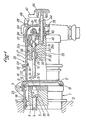
- FIGS. 1 to 3 denotes the base of a socket outlet according to the invention which comprises a body 2, for example of light alloy fixed by means not shown, in a load-bearing wall 3; in the body 2 is housed, in an integral manner, a base 4 made of insulating material in which the contact pins of bases such as 5 are immobilized connected to the phase line such as 6 by a cable clamp connection terminal which n was not otherwise represented.
- the body 2 of the base is removably closed by a cover 8 hinged at 9 on said body and subjected to the action of a spring arranged so as to give it two stable positions, one of closure (FIG. 1) and the other opening ( Figures 2 and 3).
- a seal 10 made of elastic material provides sealing.
- the contact pins 5 of the base each open at their ends 11 intended to come into contact with the end parts 12 of the pins 13 of the plug of which they are conjugated, in a chamber 14, called “breaking chamber”, by the disc 15 which has an aperture 16 of section very close to that of the end portion 12 of the corresponding plug pin which is intended to pass through it ( Figures 2 and 3).
- This provision in itself known in principle, is intended to contribute to the elimination of the risk of explosion in the case where the device must operate in an explosion-proof environment.
- the removable plug 20 of the socket has a body 21, for example made of light alloy and provided with two diametrically opposite lugs for fixing with bayonet such as 22 intended, after introduction, then low amplitude rotation of the plug in the base ( Figure 2), to cooperate, in known manner, with two opposite conjugate notches of retention, such as 23 formed in the body 2 thereof.
- the body 2 has a peripheral rib 24 intended to come to bear against the peripheral edge 17 of the base with the interposition of a seal 25 integral with said rib.
- a sliding insulating body 26 immobilized in rotation by known means and not shown; a spring 27, working under compression between a shoulder 28 of the insulating body and a shoulder 30 secured to the body 21 of the plug, tends to keep said insulating body in abutment against a second shoulder 30a of the body 21 arranged opposite the cylindrical part 41 of the latter which is intended to penetrate with a slight clearance, in the base, between the internal wall 18 of the latter and the insulating base 4.
- the insulating body 26 carries, in a sliding manner, the contact pins 13 of the plug, respectively conjugated with the corresponding contact pins 5 of the base.
- Each pin 13 is guided by the opening 29 and the passage 29a of the insulating body 26 between which is formed a co-axial housing 31 in which a spring 32 works under compression between the bottom 34 of said housing and a shoulder ring 33 secured to the spindle so as to urge the latter to protrude from the insulating body 26.
- the spring 32 is intended to provide the contact pressure between the opposite ends 11 of the socket pins and 12 of the plug pins, one and the other provided in known manner, contact pads 35, 36, made of high conductivity metal such as silver.
- the body of the plug also carries, in an integral manner, a support 37, made of insulating material, which carries the terminals 38 starting from the conductive wires 39 of the cable 40 which serves the devices to be supplied with electric current.
- Each terminal 38 is connected to the part of the corresponding pin opposite the contact pad, by a deformable conductive element.
- a tubular braid 51 brazed or crimped at each of its ends respectively on the terminal and on the spindle this arrangement being intended to allow the spindle to effect an axial displacement of a certain amplitude with respect to its contact terminal 38.
- the insulating body 26 carries axially and integrally, opposite the base 1, a rod 42 which slides with little play, in the sockets 43, 44 formed axially respectively in the support 37 and in the end cap 45 the plug body 21; the rod 42 carries on its outer end a pusher 46 which carries a hooking heel 47 arranged to cooperate with a retaining hook 48 pivotally mounted, against the action of a spring not shown, around an axis 49 carried by the cap 45 and having, opposite its active part, an operating button 50 on which it can be pressed against the action of the spring.
- the assembly is arranged in such a way that, when the pusher is urged in the direction of the cap 45, its heel 47 crosses the hook 48 which is erased by tilting against the action of its spring, then, recalled by the latter , comes to lock the pusher against the action of the spring 27 which during this maneuver has been compressed between the shoulder 28 of the sliding insulating body 26 and the shoulder 30 of the body 21 of the plug.
- the assembly is further arranged in such a way that, when the pusher is thus locked by the hook 48 and the plug has been inserted into the base and locked therein by the bayonet device 23, 24, the pins 5 of the base and 13 of the plug are in mutual contact by their pads 35, 36 against a suitable and predetermined compression of the spring 32, ' the spindle then being caused to perform an axial sliding movement of small amplitude relative to the base against the action of the spring 32 which is then compressed between the ring 33 and the bottom 34 of the housing 31.
- the disc 15 can be produced in the form of a rotatable mounted safety disc. around the axis of the base 1 against the action of a not shown return spring, which urges it up to a position of presentation of the plug pins determined by a guide groove, in the axial direction, of the pins 22.
- the openings 16 of the safety disc then mask the chambers 14. They are penetrated by the pins 13 and the disc is driven by the rotational movement applied to the plug until the bayonet device is locked, this movement sufficient to bring the openings 16 in the axis of the chambers 14 (it is recalled here that the insulating body 26 on which the pins 13 depend, is immobilized in rotation relative to the body of the plug).
- the plug With a view to establishing contact, the plug is then introduced into the base, its pins 22 passing through the conjugate axial guide grooves formed in the base.
- the pins 13 penetrate into the openings 16 of the safety disc while the pins 22 reach the bottom of the guide grooves into which open, in known manner, the notches 23 of the bayonet locking device.
- a rotational movement is then applied to the plug, the small amplitude of which is determined by the peripheral length of the notches 23; the plug has then reached its locking position in the base, shown in Figure 2, in which it is held by the bayonet device suitably shaped for this purpose.
- the springs 32 thus provide the contact pressure necessary for the proper passage of the current, pressure for which they have been previously calibrated.
- the pins 13 have moved away from the terminals 38, which is made possible by the elongation capacity of the braid 51, in a manner known per se. Said braid then takes on the appearance shown in FIG. 3.
- the speed with which the cut is made is independent of the greater or lesser freedom of movement of the body of the plug relative to the base, freedom which, in said known sockets, can, for example, be hampered by the simple weight of the cable such as 40.
- the speed of cutting depends on the invention, only on the recoil movement of the insulating body 26 under the action of the cut-off spring 27 and this movement takes place inside the closed and protected space determined by the body of the plug which remains stationary during the actual cut-off operation; the recoil movement of the insulating body cannot therefore be subjected to any obstacle of any kind, with the sole exception of the freedom of the recoil movement of the pusher which obviously poses no problem.
- the socket outlet is to operate in an explosion-proof environment, it is possible to constitute it, without disadvantage, with a very small clearance between the body of the plug and the base.
- the pneumatic pump effect is exerted only on a piston surface formed by the section of the rod 42 of the pusher increased by the section of the contact pins whose play in the openings 16 is very reduced, as is that of the rod 42 in the socket 44.
- This total section is, obviously, much less than the section of the bodies of a plug of the same dimensions and makes the pump effect negligible.
- the essential characteristic of the device described above is to make the operation of the abrupt current breaking device independent of the greater or lesser ease of relative sliding of the base and of the body of the plug due to the fact that the insulating body carrying those of the pins which are movable relative to the tubular base under the action of the spring intended to cause the abrupt break of the contact, is distinct from the body of the plug which slides in the tubular base and can therefore be in translation, independent of said body of the plug and thus, removed from the constraints which may hinder the free sliding of the latter relative to the base.
Landscapes
- Details Of Connecting Devices For Male And Female Coupling (AREA)
- Connector Housings Or Holding Contact Members (AREA)
Applications Claiming Priority (2)
| Application Number | Priority Date | Filing Date | Title |
|---|---|---|---|
| FR7923647 | 1979-09-21 | ||
| FR7923647A FR2466111A1 (fr) | 1979-09-21 | 1979-09-21 | Perfectionnements aux prises de courant a contact en bout et rupture brusque |
Publications (2)
| Publication Number | Publication Date |
|---|---|
| EP0026144A2 true EP0026144A2 (de) | 1981-04-01 |
| EP0026144A3 EP0026144A3 (de) | 1981-04-08 |
Family
ID=9229923
Family Applications (1)
| Application Number | Title | Priority Date | Filing Date |
|---|---|---|---|
| EP80401345A Withdrawn EP0026144A3 (de) | 1979-09-21 | 1980-09-19 | Stecker mit Druckkontakt und Schnapptrennung |
Country Status (2)
| Country | Link |
|---|---|
| EP (1) | EP0026144A3 (de) |
| FR (1) | FR2466111A1 (de) |
Cited By (1)
| Publication number | Priority date | Publication date | Assignee | Title |
|---|---|---|---|---|
| GB2388970A (en) * | 2002-04-19 | 2003-11-26 | Hawke Cable Glands Ltd | Connector for use in hazardous environment |
Families Citing this family (2)
| Publication number | Priority date | Publication date | Assignee | Title |
|---|---|---|---|---|
| FR2518830A1 (fr) * | 1981-12-21 | 1983-06-24 | Marechal Sepm | Prise de courant munie d'un socle a barrettes basculantes de contact et d'une fiche a poussoir |
| FR3068180B1 (fr) | 2017-06-26 | 2020-12-04 | Soc Dexploitation Des Procedes Marechal | Socle de connexion electrique comprenant un element mobile de connexion, socle complementaire de connexion electrique, et ensemble comprenant de tels socles |
Family Cites Families (7)
| Publication number | Priority date | Publication date | Assignee | Title |
|---|---|---|---|---|
| DE749157C (de) * | 1940-02-21 | 1944-11-16 | Feuchtigkeits- und gasdichte Kontaktverbindung fuer elektrische Kabel | |
| US2329479A (en) * | 1940-10-31 | 1943-09-14 | Bell Telephone Labor Inc | Electrical connector |
| BE540233A (de) * | 1954-08-05 | |||
| FR1417563A (fr) * | 1964-07-21 | 1965-11-12 | Pyle National Co | Connecteur antidéflagrant |
| US3312928A (en) * | 1964-07-21 | 1967-04-04 | Pyle National Co | Explosion-proof connector |
| US3808579A (en) * | 1972-11-06 | 1974-04-30 | Akzona Inc | Explosion proof connector |
| US4264115A (en) * | 1978-03-01 | 1981-04-28 | Bunker Ramo Corporation | Interstage electrical connector |
-
1979
- 1979-09-21 FR FR7923647A patent/FR2466111A1/fr active Granted
-
1980
- 1980-09-19 EP EP80401345A patent/EP0026144A3/de not_active Withdrawn
Cited By (1)
| Publication number | Priority date | Publication date | Assignee | Title |
|---|---|---|---|---|
| GB2388970A (en) * | 2002-04-19 | 2003-11-26 | Hawke Cable Glands Ltd | Connector for use in hazardous environment |
Also Published As
| Publication number | Publication date |
|---|---|
| EP0026144A3 (de) | 1981-04-08 |
| FR2466111B1 (de) | 1983-12-23 |
| FR2466111A1 (fr) | 1981-03-27 |
Similar Documents
| Publication | Publication Date | Title |
|---|---|---|
| EP0106931B1 (de) | Steckdose mit Schnappeinschaltung und -trennung | |
| EP0895742A1 (de) | Verbindungsanordnung für tragbares Gerät | |
| EP0117204A1 (de) | Sender zur Fernbedienung einer Schlossverriegelung | |
| EP0627786B1 (de) | Verfahren und System zur physischen Trennung zweier elektrisch verbundenen Körper | |
| CA2077050C (fr) | Sectionneur de terre a pouvoir de coupure | |
| FR2531577A1 (fr) | Contact electrique a pression a pouvoir de fermeture et d'ouverture incorpore | |
| EP0082747A2 (de) | Elektrische Steckdose ausgerüstet mit einem Hebelschaltersockel und einem Druckknopfstecker | |
| EP1075055B1 (de) | Stromverteilereinrichtung mit mechanischer Steuerverriegelung des Steckers in der entsprechenden Steckdose | |
| EP1318569B1 (de) | Elektrischer Steckanschluss mit Verschlussbuchsenblenden und Baureihe mit einem solchen Steckanschluss | |
| EP0074288B1 (de) | Automatische Begrenzungsvorrichtung für Kurzschlussströme | |
| FR2584873A1 (fr) | Systeme de raccordement electrique pour un reseau specifique de distribution de courant, et adaptateur pour fiche de raccordement electrique et socle de prise de courant correspondants | |
| FR2466111A1 (fr) | Perfectionnements aux prises de courant a contact en bout et rupture brusque | |
| EP0515268A1 (de) | Varistor Einführvorrichtung, eingebaut in einem Hochspannungslastschalter | |
| FR2625847A1 (fr) | Dispositif de connexion magnetique entre une ampoule et sa douille | |
| BE1006139A3 (fr) | Desengagement automatique de fiches electriques. | |
| FR2563383A1 (fr) | Fiche de prise de courant a element de traction | |
| FR2594604A1 (fr) | Systeme de contact electrique embrochable | |
| EP0012087B1 (de) | Unterteil zum elektrischen Anschluss eines Gerätes an einen Sockel | |
| EP0654857B1 (de) | Elektrischen Steckanschluss mit ausklappbarer Verschlussblende | |
| FR2545657A1 (fr) | Perfectionnements aux dispositifs de securite pour connexion electrique, utilisables en particulier en tant que prises de courant | |
| CA1273043A (fr) | Disjoncteur a haute tension a gaz dielectrique a resistance de fermeture | |
| FR2648615A1 (fr) | Perfectionnements aux interrupteurs a coupure automatique, notamment aux disjoncteurs et disjoncteurs differentiels | |
| FR2589013A3 (fr) | Appareillage de verrouillage associe a des appareils a levier de coupure et/ou de protection alimentant une prise de courant electrique | |
| EP0033287B1 (de) | Sicherheitsfassung für eine röhrenförmige Lampe mit axialen Endkappen | |
| EP0327460A1 (de) | Elektrischer Schalter mit automatischer Ausschaltung, insbesondere Differentialschutz |
Legal Events
| Date | Code | Title | Description |
|---|---|---|---|
| PUAI | Public reference made under article 153(3) epc to a published international application that has entered the european phase |
Free format text: ORIGINAL CODE: 0009012 |
|
| PUAL | Search report despatched |
Free format text: ORIGINAL CODE: 0009013 |
|
| AK | Designated contracting states |
Designated state(s): DE GB |
|
| AK | Designated contracting states |
Designated state(s): DE GB |
|
| STAA | Information on the status of an ep patent application or granted ep patent |
Free format text: STATUS: THE APPLICATION IS DEEMED TO BE WITHDRAWN |
|
| 18D | Application deemed to be withdrawn |
Effective date: 19820314 |
|
| RIN1 | Information on inventor provided before grant (corrected) |
Inventor name: WELU, PROSPER |