EP0515268A1 - Varistor Einführvorrichtung, eingebaut in einem Hochspannungslastschalter - Google Patents
Varistor Einführvorrichtung, eingebaut in einem Hochspannungslastschalter Download PDFInfo
- Publication number
- EP0515268A1 EP0515268A1 EP92401369A EP92401369A EP0515268A1 EP 0515268 A1 EP0515268 A1 EP 0515268A1 EP 92401369 A EP92401369 A EP 92401369A EP 92401369 A EP92401369 A EP 92401369A EP 0515268 A1 EP0515268 A1 EP 0515268A1
- Authority
- EP
- European Patent Office
- Prior art keywords
- tube
- contact
- circuit breaker
- rod
- sleeve
- Prior art date
- Legal status (The legal status is an assumption and is not a legal conclusion. Google has not performed a legal analysis and makes no representation as to the accuracy of the status listed.)
- Granted
Links
- 230000037431 insertion Effects 0.000 title claims abstract description 25
- 238000003780 insertion Methods 0.000 title claims abstract description 25
- 229910052751 metal Inorganic materials 0.000 claims abstract description 18
- 239000002184 metal Substances 0.000 claims abstract description 18
- 230000000295 complement effect Effects 0.000 claims abstract description 4
- 238000007664 blowing Methods 0.000 claims description 11
- 239000007789 gas Substances 0.000 claims description 9
- 238000005192 partition Methods 0.000 claims description 5
- -1 polytetrafluoroethylene Polymers 0.000 claims description 4
- 229920001343 polytetrafluoroethylene Polymers 0.000 claims description 4
- 239000004810 polytetrafluoroethylene Substances 0.000 claims description 4
- 239000003990 capacitor Substances 0.000 claims description 3
- 238000006073 displacement reaction Methods 0.000 claims description 3
- 239000007769 metal material Substances 0.000 claims description 3
- 239000004020 conductor Substances 0.000 claims description 2
- 230000000694 effects Effects 0.000 claims description 2
- 238000010891 electric arc Methods 0.000 claims description 2
- 238000000926 separation method Methods 0.000 description 6
- RYGMFSIKBFXOCR-UHFFFAOYSA-N Copper Chemical compound [Cu] RYGMFSIKBFXOCR-UHFFFAOYSA-N 0.000 description 2
- 239000011810 insulating material Substances 0.000 description 2
- 229910001369 Brass Inorganic materials 0.000 description 1
- PXGOKWXKJXAPGV-UHFFFAOYSA-N Fluorine Chemical compound FF PXGOKWXKJXAPGV-UHFFFAOYSA-N 0.000 description 1
- 229910018503 SF6 Inorganic materials 0.000 description 1
- 239000004809 Teflon Substances 0.000 description 1
- 229920006362 Teflon® Polymers 0.000 description 1
- 241001080024 Telles Species 0.000 description 1
- 229910052790 beryllium Inorganic materials 0.000 description 1
- ATBAMAFKBVZNFJ-UHFFFAOYSA-N beryllium atom Chemical compound [Be] ATBAMAFKBVZNFJ-UHFFFAOYSA-N 0.000 description 1
- DMFGNRRURHSENX-UHFFFAOYSA-N beryllium copper Chemical compound [Be].[Cu] DMFGNRRURHSENX-UHFFFAOYSA-N 0.000 description 1
- 239000010951 brass Substances 0.000 description 1
- 238000005219 brazing Methods 0.000 description 1
- 239000000919 ceramic Substances 0.000 description 1
- 230000006835 compression Effects 0.000 description 1
- 238000007906 compression Methods 0.000 description 1
- 239000000470 constituent Substances 0.000 description 1
- 229910052802 copper Inorganic materials 0.000 description 1
- 239000010949 copper Substances 0.000 description 1
- 238000013016 damping Methods 0.000 description 1
- 229910052731 fluorine Inorganic materials 0.000 description 1
- 239000011737 fluorine Substances 0.000 description 1
- 229920000642 polymer Polymers 0.000 description 1
- 229910052573 porcelain Inorganic materials 0.000 description 1
- 239000000843 powder Substances 0.000 description 1
- SFZCNBIFKDRMGX-UHFFFAOYSA-N sulfur hexafluoride Chemical compound FS(F)(F)(F)(F)F SFZCNBIFKDRMGX-UHFFFAOYSA-N 0.000 description 1
- 229960000909 sulfur hexafluoride Drugs 0.000 description 1
Images


Classifications
-
- H—ELECTRICITY
- H01—ELECTRIC ELEMENTS
- H01H—ELECTRIC SWITCHES; RELAYS; SELECTORS; EMERGENCY PROTECTIVE DEVICES
- H01H33/00—High-tension or heavy-current switches with arc-extinguishing or arc-preventing means
- H01H33/02—Details
- H01H33/04—Means for extinguishing or preventing arc between current-carrying parts
- H01H33/16—Impedances connected with contacts
- H01H33/168—Impedances connected with contacts the impedance being inserted both while closing and while opening the switch
-
- H—ELECTRICITY
- H01—ELECTRIC ELEMENTS
- H01H—ELECTRIC SWITCHES; RELAYS; SELECTORS; EMERGENCY PROTECTIVE DEVICES
- H01H33/00—High-tension or heavy-current switches with arc-extinguishing or arc-preventing means
- H01H33/70—Switches with separate means for directing, obtaining, or increasing flow of arc-extinguishing fluid
- H01H33/76—Switches with separate means for directing, obtaining, or increasing flow of arc-extinguishing fluid wherein arc-extinguishing gas is evolved from stationary parts; Selection of material therefor
- H01H33/765—Switches with separate means for directing, obtaining, or increasing flow of arc-extinguishing fluid wherein arc-extinguishing gas is evolved from stationary parts; Selection of material therefor the gas-evolving material being incorporated in the contact material
Definitions
- the present invention relates to a device allowing electrical insertion in parallel on the contacts of a circuit breaker, during the opening and closing of the latter, of a varistor or of a resistor or of an assembly comprising both a resistor and a varistor, this varistor or this resistor or this assembly being disposed inside the envelope containing the breaking chamber of the circuit breaker.
- a circuit breaker comprising, inside the breaking chamber, auxiliary contacts allowing insertion for a limited period after the separation of the contacts of the circuit breaker, of a capacity .
- a hook keeps the auxiliary contacts engaged against the action of a compressed spring; clearing the hook releases the spring which opens the auxiliary contacts.
- the spring is again compressed by an arm linked to the main moving contact of the circuit breaker.
- Such a device is bulky and complex, which increases the price of the device due to the need to greatly increase the volume of the breaking chamber; such a device is heavy and increases the energy required to operate the circuit breaker; such a device has a spring which is compressed while the circuit breaker is open, which presents the risk of inadvertent reclosing of the device and goes seriously against safety.
- Another object of the invention is to provide a device allowing insertion for a sufficient time after the separation of the arcing contacts during opening of the circuit breaker to allow effective reduction of opening overvoltages.
- the device necessarily comprises two contacts which separate after insertion; another object of the invention is to provide an insertion device which, after the insertion time has elapsed, performs rapid disinsertion so as to cut the residual arc without difficulty.
- Another object of the invention is to provide an insertion device which, despite a rapid relative displacement of its constituent elements, has damping means to avoid sudden operation.
- Another object of the invention is to provide a device allowing insertion on opening and also, if desired by the user, on closing of the circuit breaker.
- the invention relates to a device for the momentary insertion, in parallel on the contacts of a circuit breaker, at the start of the opening or at the start of the closing of said circuit breaker, of an electrical component chosen from among the resistors, varistors, capacitors or a combination of these elements, said circuit breaker comprising, for each phase, at least one breaking chamber comprising a sealed insulating envelope filled with good gases dielectric properties and comprising inside a fixed main contact connected to a first socket and a fixed arcing contact, and a movable assembly comprising a movable main contact connected to a second socket, a movable arcing contact and an operating rod, said circuit breaker further comprising inside said chamber said electrical component connected on the one hand to said first socket and on the other hand to at least one contact arm carrying a contact ring, characterized in that it comprises a metal tube mechanically and electrically connected to said movable main contact, a rod which can slide inside said tube, said rod comprising at a first end a metal contact s
- said stop carries an O-ring and is made of polytetrafluoroethylene.
- the end of the contact sleeve adjacent to the contact arm is made of a metallic material impregnated with a product giving off, under the effect of the electric arc, a gas.
- the arm contact is made in the form of a tube provided at one end with contact fingers and provided with a partition to delimit a blowing volume, an insulating nozzle surrounding the contact fingers.
- the reference 1 designates an insulating envelope, preferably of porcelain, delimiting a volume 2 containing the breaking elements of the circuit breaker.
- the insulating envelope is closed at one end by a metal plate 3, fixed to a metal crown 4 constituting a first and extended socket, inside the envelope by arms 5 to which are fixed a first metal tube 6 constituting the main fixed contact, and a second tube 7, coaxial with the first, constituting the fixed arcing contact.
- Volume 2 is filled with a gas with good dielectric properties, such as sulfur hexafluoride, under a pressure of a few bars.
- the mobile assembly of the circuit breaker comprises a metal tube 9, extended by a corona hood 10, and provided with a transverse metal partition 11 carrying contact fingers 12 constituting the movable main contact, and a blowing tube 13 extended by contact fingers 14 constituting the movable arcing contact.
- the partition 11, pierced with holes 15 for the passage of the blowing gas, carries a blowing nozzle 17 made of insulating material.
- the blowing is provided by a fixed piston placed inside the tube 9, and not shown in FIG. 1.
- the tube 9 is connected, by sliding contacts, not shown, to a second outlet of the circuit breaker.
- a varistor is placed inside the volume 2. This consists of a stack of discs 18 placed in an insulating tube 19, fixed at one end to the plate 3 and closed at the other end by a metal block 20 .
- the varistor can be associated with several ohmic elements (resistance); the invention also applies to circuit breakers in which there are only ohmic elements.
- the invention applies to any circuit breaker in which an electrical component (varistor, resistor, capacitor, or any combination of these elements) must be inserted, either at the opening of the circuit breaker, or at the closing , either during these two maneuvers.
- the insertion device of the invention is generally represented at 30 in FIG. 1. It cooperates with a contact consisting of arms 31, fixed to the metal block 20 and carrying a metal crown 31A ..
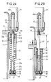
- FIG. 2A A detailed embodiment of the insertion device is shown in Figures 2A and 2B.
- the insertion device comprises a metal tube 32, having a projection 32A by which the tube is mechanically fixed and electrically connected to the tube 9, for example by brazing.
- a sleeve 33 for example made of Teflon.
- the sleeve 33 and the tube 32 define a housing in which is housed a first end of a spring 34 which bears against a shoulder 32B formed inside the tube 32.
- the sleeve 33 is screwed onto the shoulder 32C.
- An insulating washer 35 is glued to the upper end of the tube 32.
- the lower end of the tube 32 has an inner profile 32D of conical shape, the role of which will be explained below.
- a rod 37 for example made of high-strength brass, terminated by a portion 37 A of larger diameter pierced with a threaded bore 37B.
- a shoulder 37C serves as a support for the second end of the spring 34.
- a stop or ring 38 On the lower end of the portion 37A is engaged a stop or ring 38, with conical external profile, preferably made made of polytetrafluoroethylene, and provided with an O-ring 39.
- the ring 38 is held in place by the head of a bolt 40, screwed into the bore 37B with the interposition of rings 41 and 42.
- a contact sleeve 43 advantageously made of copper.
- the device also allows the varistor to be inserted when the circuit breaker closes. It is enough for this that the end of the sleeve 43 comes into contact with the ring 31A before the arcing contacts 7 and 14 come into contact.
- the distance a determines the insertion time at closing, the duration of which is usually of the order of 8 ms. If, at rest, the end of the movable arcing contact 14 and the end 43A of the contact sleeve 43 are at the same level, and if the distance a is zero, there can be no insertion of the varistor when closing of the circuit breaker.
- FIG. 3 represents an alternative embodiment of the device, which can advantageously be used for circuit-breakers with a metal ground shell, in which there is a relatively large space around the breaking elements.
- the contact arms 31 are replaced by a tube 50 terminated by contact fingers 51.
- the tube has a bottom 53, so that its internal volume 56 constitutes a blowing volume of the arc which is established at the separation of the fingers 51 and the contact 43A.
- a nozzle 54 made of an insulating material such as polytetrafluoroethylene, promotes this blowing.
- the tube 32 of the device is fixed to the movable tube by an arm 55.
- distance a is equal to zero, there is no insertion of a varistor when the circuit breaker closes.
- the invention applies to high-voltage circuit breakers of the conventional type with a ceramic shell or of the type with a metal shell on the ground.
Landscapes
- Circuit Breakers (AREA)
- Emergency Protection Circuit Devices (AREA)
- Thermistors And Varistors (AREA)
- Arc-Extinguishing Devices That Are Switches (AREA)
Applications Claiming Priority (2)
| Application Number | Priority Date | Filing Date | Title |
|---|---|---|---|
| FR9106159A FR2676857B1 (fr) | 1991-05-22 | 1991-05-22 | Dispositif d'insertion d'une varistance, incorpore dans un disjoncteur a haute tension. |
| FR9106159 | 1991-05-22 |
Publications (2)
| Publication Number | Publication Date |
|---|---|
| EP0515268A1 true EP0515268A1 (de) | 1992-11-25 |
| EP0515268B1 EP0515268B1 (de) | 1996-01-03 |
Family
ID=9413003
Family Applications (1)
| Application Number | Title | Priority Date | Filing Date |
|---|---|---|---|
| EP92401369A Expired - Lifetime EP0515268B1 (de) | 1991-05-22 | 1992-05-20 | Varistor Einführvorrichtung, eingebaut in einem Hochspannungslastschalter |
Country Status (7)
| Country | Link |
|---|---|
| US (1) | US5264671A (de) |
| EP (1) | EP0515268B1 (de) |
| AT (1) | ATE132655T1 (de) |
| CA (1) | CA2069185C (de) |
| DE (1) | DE69207265T2 (de) |
| ES (1) | ES2081584T3 (de) |
| FR (1) | FR2676857B1 (de) |
Cited By (1)
| Publication number | Priority date | Publication date | Assignee | Title |
|---|---|---|---|---|
| FR2712118A1 (fr) * | 1993-11-02 | 1995-05-12 | Gec Alsthom T & D Sa | Disjoncteur avec dispositif d'insertion d'un composant électrique. |
Families Citing this family (6)
| Publication number | Priority date | Publication date | Assignee | Title |
|---|---|---|---|---|
| US6316742B1 (en) | 1999-07-14 | 2001-11-13 | Southern States, Inc. | Limited restrike circuit interrupter used as a line capacitor and load switch |
| US6236010B1 (en) | 1999-07-14 | 2001-05-22 | Southern States, Inc. | Circuit interrupter including a penetrating electrical contact with grip and release structure |
| CA2851850C (en) * | 2013-06-05 | 2015-10-20 | Mersen Usa Newburyport-Ma, Llc | Circuit protection device |
| KR101797021B1 (ko) * | 2014-10-23 | 2017-11-13 | 엘에스산전 주식회사 | 초고압 차단기의 투입 저항 지지 구조 |
| CN113839371A (zh) * | 2020-06-24 | 2021-12-24 | 张健 | 一种自动变阻抗转移电流开断的直流断路器 |
| US12112905B2 (en) | 2022-11-17 | 2024-10-08 | Southern States, Llc | Alternative gas current pause circuit interrupter |
Citations (4)
| Publication number | Priority date | Publication date | Assignee | Title |
|---|---|---|---|---|
| GB1178324A (en) * | 1960-12-15 | 1970-01-21 | Asea Ab | Improvements in Air Blast Electric Circuit Breakers. |
| DE2459861A1 (de) * | 1974-11-22 | 1976-05-26 | Bbc Brown Boveri & Cie | Elektrischer schalter mit einschaltwiderstand |
| GB2032180A (en) * | 1978-09-12 | 1980-04-30 | Westinghouse Electric Corp | Circuit-interrupters |
| EP0050341A2 (de) * | 1980-10-20 | 1982-04-28 | Hitachi, Ltd. | Druckgasschalter des Widerstandsschaltstellentyps |
Family Cites Families (2)
| Publication number | Priority date | Publication date | Assignee | Title |
|---|---|---|---|---|
| DE3412824A1 (de) * | 1984-04-05 | 1985-10-17 | Doduco KG Dr. Eugen Dürrwächter, 7530 Pforzheim | Elektrischer lastschalter, insbesondere zur verwendung in mittelspannungsschaltgeraeten |
| FR2663456B1 (fr) * | 1990-06-14 | 1996-04-26 | Alsthom Gec | Disjoncteur a varistance incorporee. |
-
1991
- 1991-05-22 FR FR9106159A patent/FR2676857B1/fr not_active Expired - Fee Related
-
1992
- 1992-05-20 EP EP92401369A patent/EP0515268B1/de not_active Expired - Lifetime
- 1992-05-20 DE DE69207265T patent/DE69207265T2/de not_active Expired - Fee Related
- 1992-05-20 AT AT92401369T patent/ATE132655T1/de not_active IP Right Cessation
- 1992-05-20 ES ES92401369T patent/ES2081584T3/es not_active Expired - Lifetime
- 1992-05-21 US US07/886,191 patent/US5264671A/en not_active Expired - Fee Related
- 1992-05-21 CA CA002069185A patent/CA2069185C/fr not_active Expired - Fee Related
Patent Citations (4)
| Publication number | Priority date | Publication date | Assignee | Title |
|---|---|---|---|---|
| GB1178324A (en) * | 1960-12-15 | 1970-01-21 | Asea Ab | Improvements in Air Blast Electric Circuit Breakers. |
| DE2459861A1 (de) * | 1974-11-22 | 1976-05-26 | Bbc Brown Boveri & Cie | Elektrischer schalter mit einschaltwiderstand |
| GB2032180A (en) * | 1978-09-12 | 1980-04-30 | Westinghouse Electric Corp | Circuit-interrupters |
| EP0050341A2 (de) * | 1980-10-20 | 1982-04-28 | Hitachi, Ltd. | Druckgasschalter des Widerstandsschaltstellentyps |
Cited By (1)
| Publication number | Priority date | Publication date | Assignee | Title |
|---|---|---|---|---|
| FR2712118A1 (fr) * | 1993-11-02 | 1995-05-12 | Gec Alsthom T & D Sa | Disjoncteur avec dispositif d'insertion d'un composant électrique. |
Also Published As
| Publication number | Publication date |
|---|---|
| FR2676857A1 (fr) | 1992-11-27 |
| DE69207265T2 (de) | 1996-05-15 |
| CA2069185A1 (fr) | 1992-11-23 |
| EP0515268B1 (de) | 1996-01-03 |
| FR2676857B1 (fr) | 1994-04-08 |
| ATE132655T1 (de) | 1996-01-15 |
| DE69207265D1 (de) | 1996-02-15 |
| ES2081584T3 (es) | 1996-03-16 |
| CA2069185C (fr) | 1996-07-23 |
| US5264671A (en) | 1993-11-23 |
Similar Documents
| Publication | Publication Date | Title |
|---|---|---|
| CA2035688C (fr) | Disjoncteur a moyenne ou haute tension a autosoufflage | |
| FR2668648A1 (fr) | Disjoncteur a sf6 a condensateur incorpore. | |
| EP0302390B1 (de) | Druckgasschalter für Hoch- oder Mittelspannung mit von der Lichtbogenenergie entnommener Ausschaltenergie | |
| CA2044517C (fr) | Disjoncteur a varistance incorporee | |
| EP0807946B1 (de) | Hochspannungs-Blaskolbenschalter | |
| CA2069185C (fr) | Dispositif d'insertion d'une varistance, incorpore dans un disjoncteur a haute tension | |
| CA2206950C (fr) | Disjoncteur a haute tension avec insertion de resistance a la fermeture. | |
| EP0454035A1 (de) | Mittel- oder Hochspannungsschalter mit aneinanderstossenden Lichtbogenkontakten | |
| EP0759629B1 (de) | Lastschalter mit Einschaltwiderstand und Einfügungsvorrichtung | |
| EP0785562A1 (de) | Lastschalter mit Kontakten mit Doppelbewegung | |
| EP0415098A1 (de) | Selbstblasschalter für Mittelspannung | |
| EP0456025B1 (de) | Hochspannungsschalter mit Hilfslichtbogen in Reihe | |
| EP0560665B1 (de) | Trägheitskontakt | |
| EP0458236B1 (de) | Mittelspannungsschalter | |
| EP0406794A1 (de) | Hoch- oder Mittelspannungslastschalter | |
| CA2281971C (fr) | Interrupteur avec un systeme d'insertion d'une resistance a longue duree d'insertion | |
| EP0884745A1 (de) | Leistungsschalter mit einem Einschaltwiderstand | |
| FR2589618A1 (fr) | Dispositif de protection pour condensateur en boitier etanche | |
| FR2694987A1 (fr) | Disjoncteur à haute tension ayant une chambre de coupure à volume de soufflage variable. | |
| FR2563372A1 (fr) | Disjoncteur haute tension a soufflage d'arc | |
| FR2737937A1 (fr) | Disjoncteur a double mouvement avec resistance de fermeture | |
| FR2657459A1 (fr) | Disjoncteur a haute tension a resistance de fermeture. | |
| FR2751781A1 (fr) | Disjoncteur avec insertion temporaire de resistance a la fermeture | |
| FR2738388A1 (fr) | Disjoncteur a faible energie de manoeuvre | |
| FR2720544A1 (fr) | Disjoncteur à ouverture assistée par effet électro-dynamique. |
Legal Events
| Date | Code | Title | Description |
|---|---|---|---|
| PUAI | Public reference made under article 153(3) epc to a published international application that has entered the european phase |
Free format text: ORIGINAL CODE: 0009012 |
|
| AK | Designated contracting states |
Kind code of ref document: A1 Designated state(s): AT BE CH DE DK ES FR GB GR IT LI LU MC NL PT SE |
|
| 17P | Request for examination filed |
Effective date: 19930303 |
|
| 17Q | First examination report despatched |
Effective date: 19941128 |
|
| GRAA | (expected) grant |
Free format text: ORIGINAL CODE: 0009210 |
|
| AK | Designated contracting states |
Kind code of ref document: B1 Designated state(s): AT BE CH DE DK ES FR GB GR IT LI LU MC NL PT SE |
|
| PG25 | Lapsed in a contracting state [announced via postgrant information from national office to epo] |
Ref country code: NL Free format text: LAPSE BECAUSE OF FAILURE TO SUBMIT A TRANSLATION OF THE DESCRIPTION OR TO PAY THE FEE WITHIN THE PRESCRIBED TIME-LIMIT Effective date: 19960103 Ref country code: GR Free format text: LAPSE BECAUSE OF FAILURE TO SUBMIT A TRANSLATION OF THE DESCRIPTION OR TO PAY THE FEE WITHIN THE PRESCRIBED TIME-LIMIT Effective date: 19960103 Ref country code: DK Effective date: 19960103 |
|
| REF | Corresponds to: |
Ref document number: 132655 Country of ref document: AT Date of ref document: 19960115 Kind code of ref document: T |
|
| ITF | It: translation for a ep patent filed | ||
| REF | Corresponds to: |
Ref document number: 69207265 Country of ref document: DE Date of ref document: 19960215 |
|
| REG | Reference to a national code |
Ref country code: CH Ref legal event code: NV Representative=s name: GEC ALSTHOM (SUISSE) S.A. DEPARTEMENT DES BREVETS |
|
| REG | Reference to a national code |
Ref country code: ES Ref legal event code: FG2A Ref document number: 2081584 Country of ref document: ES Kind code of ref document: T3 |
|
| PG25 | Lapsed in a contracting state [announced via postgrant information from national office to epo] |
Ref country code: PT Effective date: 19960403 |
|
| PGFP | Annual fee paid to national office [announced via postgrant information from national office to epo] |
Ref country code: GB Payment date: 19960417 Year of fee payment: 5 |
|
| PGFP | Annual fee paid to national office [announced via postgrant information from national office to epo] |
Ref country code: SE Payment date: 19960422 Year of fee payment: 5 Ref country code: DE Payment date: 19960422 Year of fee payment: 5 |
|
| GBT | Gb: translation of ep patent filed (gb section 77(6)(a)/1977) |
Effective date: 19960326 |
|
| PGFP | Annual fee paid to national office [announced via postgrant information from national office to epo] |
Ref country code: CH Payment date: 19960508 Year of fee payment: 5 |
|
| PGFP | Annual fee paid to national office [announced via postgrant information from national office to epo] |
Ref country code: ES Payment date: 19960513 Year of fee payment: 5 |
|
| PGFP | Annual fee paid to national office [announced via postgrant information from national office to epo] |
Ref country code: FR Payment date: 19960524 Year of fee payment: 5 |
|
| PG25 | Lapsed in a contracting state [announced via postgrant information from national office to epo] |
Ref country code: MC Effective date: 19960531 Ref country code: LU Free format text: LAPSE BECAUSE OF NON-PAYMENT OF DUE FEES Effective date: 19960531 Ref country code: BE Effective date: 19960531 |
|
| PGFP | Annual fee paid to national office [announced via postgrant information from national office to epo] |
Ref country code: AT Payment date: 19960531 Year of fee payment: 5 |
|
| NLV1 | Nl: lapsed or annulled due to failure to fulfill the requirements of art. 29p and 29m of the patents act | ||
| PLBE | No opposition filed within time limit |
Free format text: ORIGINAL CODE: 0009261 |
|
| STAA | Information on the status of an ep patent application or granted ep patent |
Free format text: STATUS: NO OPPOSITION FILED WITHIN TIME LIMIT |
|
| BERE | Be: lapsed |
Owner name: S.A. GEC ALSTHOM Effective date: 19960531 |
|
| 26N | No opposition filed | ||
| PG25 | Lapsed in a contracting state [announced via postgrant information from national office to epo] |
Ref country code: GB Effective date: 19970520 Ref country code: AT Effective date: 19970520 |
|
| PG25 | Lapsed in a contracting state [announced via postgrant information from national office to epo] |
Ref country code: SE Effective date: 19970521 Ref country code: ES Free format text: LAPSE BECAUSE OF NON-PAYMENT OF DUE FEES Effective date: 19970521 |
|
| PG25 | Lapsed in a contracting state [announced via postgrant information from national office to epo] |
Ref country code: LI Free format text: LAPSE BECAUSE OF NON-PAYMENT OF DUE FEES Effective date: 19970531 Ref country code: CH Free format text: LAPSE BECAUSE OF NON-PAYMENT OF DUE FEES Effective date: 19970531 |
|
| GBPC | Gb: european patent ceased through non-payment of renewal fee |
Effective date: 19970520 |
|
| REG | Reference to a national code |
Ref country code: CH Ref legal event code: PL |
|
| PG25 | Lapsed in a contracting state [announced via postgrant information from national office to epo] |
Ref country code: FR Free format text: LAPSE BECAUSE OF NON-PAYMENT OF DUE FEES Effective date: 19980130 |
|
| EUG | Se: european patent has lapsed |
Ref document number: 92401369.1 |
|
| PG25 | Lapsed in a contracting state [announced via postgrant information from national office to epo] |
Ref country code: DE Free format text: LAPSE BECAUSE OF NON-PAYMENT OF DUE FEES Effective date: 19980203 |
|
| REG | Reference to a national code |
Ref country code: FR Ref legal event code: ST |
|
| REG | Reference to a national code |
Ref country code: ES Ref legal event code: FD2A Effective date: 19990405 |
|
| PG25 | Lapsed in a contracting state [announced via postgrant information from national office to epo] |
Ref country code: IT Free format text: LAPSE BECAUSE OF NON-PAYMENT OF DUE FEES;WARNING: LAPSES OF ITALIAN PATENTS WITH EFFECTIVE DATE BEFORE 2007 MAY HAVE OCCURRED AT ANY TIME BEFORE 2007. THE CORRECT EFFECTIVE DATE MAY BE DIFFERENT FROM THE ONE RECORDED. Effective date: 20050520 |