EP0026403A1 - Mikrofilm-Durchlaufaufnahmegerät - Google Patents
Mikrofilm-Durchlaufaufnahmegerät Download PDFInfo
- Publication number
- EP0026403A1 EP0026403A1 EP19800105597 EP80105597A EP0026403A1 EP 0026403 A1 EP0026403 A1 EP 0026403A1 EP 19800105597 EP19800105597 EP 19800105597 EP 80105597 A EP80105597 A EP 80105597A EP 0026403 A1 EP0026403 A1 EP 0026403A1
- Authority
- EP
- European Patent Office
- Prior art keywords
- original
- station
- measuring
- illuminating
- template
- Prior art date
- Legal status (The legal status is an assumption and is not a legal conclusion. Google has not performed a legal analysis and makes no representation as to the accuracy of the status listed.)
- Granted
Links
- 238000003384 imaging method Methods 0.000 claims description 18
- 238000001000 micrograph Methods 0.000 abstract 1
- 230000005540 biological transmission Effects 0.000 description 5
- 238000005286 illumination Methods 0.000 description 3
- 239000000463 material Substances 0.000 description 2
- 239000011521 glass Substances 0.000 description 1
Images
Classifications
-
- G—PHYSICS
- G03—PHOTOGRAPHY; CINEMATOGRAPHY; ANALOGOUS TECHNIQUES USING WAVES OTHER THAN OPTICAL WAVES; ELECTROGRAPHY; HOLOGRAPHY
- G03B—APPARATUS OR ARRANGEMENTS FOR TAKING PHOTOGRAPHS OR FOR PROJECTING OR VIEWING THEM; APPARATUS OR ARRANGEMENTS EMPLOYING ANALOGOUS TECHNIQUES USING WAVES OTHER THAN OPTICAL WAVES; ACCESSORIES THEREFOR
- G03B27/00—Photographic printing apparatus
- G03B27/32—Projection printing apparatus, e.g. enlarger, copying camera
- G03B27/52—Details
- G03B27/62—Holders for the original
- G03B27/6207—Holders for the original in copying cameras
- G03B27/625—Apparatus which relate to the handling of originals, e.g. presence detectors, inverters
- G03B27/6264—Arrangements for moving several originals one after the other to or through an exposure station
-
- G—PHYSICS
- G03—PHOTOGRAPHY; CINEMATOGRAPHY; ANALOGOUS TECHNIQUES USING WAVES OTHER THAN OPTICAL WAVES; ELECTROGRAPHY; HOLOGRAPHY
- G03B—APPARATUS OR ARRANGEMENTS FOR TAKING PHOTOGRAPHS OR FOR PROJECTING OR VIEWING THEM; APPARATUS OR ARRANGEMENTS EMPLOYING ANALOGOUS TECHNIQUES USING WAVES OTHER THAN OPTICAL WAVES; ACCESSORIES THEREFOR
- G03B27/00—Photographic printing apparatus
- G03B27/32—Projection printing apparatus, e.g. enlarger, copying camera
- G03B27/52—Details
- G03B27/54—Lamp housings; Illuminating means
- G03B27/542—Lamp housings; Illuminating means for copying cameras, reflex exposure lighting
Definitions
- the invention relates to a microfilm continuous recording device in which the originals to be filmed are guided past an imaging station in which both the front side and, at least optionally, the back side of an original are simultaneously imaged on a micro-image carrier in a reduced scale, lighting means being provided for at least optionally illuminating both sides of the original in the area of the imaging station, and in which, in the direction of transport of the originals, a measuring station for measuring the original brightness is arranged in front of the imaging station with illuminating means for illuminating at least a selected part of the original in the area of the imaging station and one side of the Original oppositely arranged measuring element.
- the measuring station comprises an illumination lamp directed towards the front side of the original and a measuring element which registers the light remitted by the front side of the original and generates a corresponding output signal.
- the output signal is used for exposure tion control, whereby different brightness of the various originals to be filmed is compensated for in the sense of an optimal, uniform exposure of the recording material.
- the known device works optimally only if only the front of the templates is filmed and the individual templates have the same transparency.
- duplex filming exposure errors occur that are outside the standard film density range when mixed-thickness originals or different transparency of the originals are used.
- the microfilm material has a very steep gradation, even small errors in the exposure lead to results that are sometimes unusable.
- the exposure errors result from the fact that both the front and the back of the originals are illuminated in the duplex filming in the imaging station, so that the actual brightness of the imaged original is influenced both by the reflectance value of the front side of the original and by the transmission value of the original itself becomes. In contrast, only the reflectance value of the front of the original is taken into account in the measuring station.
- the invention is therefore based on the object of developing a microfilm continuous recording device according to the generic term in such a way that exposure errors are largely avoided in a simple manner in the case of duplex filming.
- a single light source can be projected onto both sides of the original, but it is expedient to A lighting fixture is arranged on each side of the template.
- the lighting fixtures are preferably arranged relative to the template such that the light from both the illuminating means of the imaging station and the illuminating means of the measuring station is incident on the template at the same angle.
- the transmission of the originals is detected when the original brightness is determined by the measuring element arranged on the front of the original. Remission light from the front side of the original and the transmission light passing through the original thus enter the measuring element.
- the light conditions on the original are thus the same both in the measuring station and in the imaging station, since in the case of duplex filming, due to the illuminating means arranged both on the front and on the rear of the originals, remission light as well as transmission light also occur.
- Originals of different transparency can thus be filmed without exposure errors.
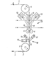
- the individual templates 2 to be filmed are fed via an input station to the template transport path 1, in which they are conveyed by means of transport means such as transport belts (not shown), deflection rollers 3 and pairs of transport rollers 5, 6 and 7, 8 the device is transported to a template output station.
- transport means such as transport belts (not shown), deflection rollers 3 and pairs of transport rollers 5, 6 and 7, 8 the device is transported to a template output station.
- the templates between the pairs of transport rollers 5, 6 and 7, 8 to be by a reference number 9 be drawn imaging station in which they are guided between two transparent glass plates 10, 11 in the recording plane.
- Two lamps or lamp banks 12, 13 are provided for illuminating the front or back of the original.
- a measuring device 14 comprising photoelectric elements is provided in front of the imaging station 9, which measures the brightness of a specific, selected area of the original to be filmed and whose output signal is used for exposure control.
- the exposure control can be carried out, for example, in the manner described in DE-AS 27 46 990.
- a lamp 16, 17 is provided on both sides of the template transport path, the light of which is directed onto the front and rear of the area 15.
- the measuring element 14 receives not only the light reflected by the lamp 16 in the area 15, but also transmission light from the lamp 17.
- the lighting conditions in the measuring station 18 thus correspond to the lighting conditions in the imaging station 9.
- the lamps 16 and 17 are preferred so arranged that the angle of their lighting direction with the original transport path 1 is the same as the angle of the lighting direction of the illumination lamps 12 and 13 with the original transport path in the region of the imaging plane.
- the illuminating lamp 13 and the lamp 17 are switched off, so that comparable lighting conditions prevail in the imaging station and in the measuring station.
Landscapes
- Physics & Mathematics (AREA)
- General Physics & Mathematics (AREA)
- Projection-Type Copiers In General (AREA)
Abstract
Description
- Die Erfindung betrifft ein Mikrofilm-Durchlaufaufnahmegerät, bei dem die zu verfilmenden Vorlagen an einer Abbildungsstation vorbeigeführt werden, in der sowohl die Vorderseite als auch, zumindest wahlweise, die Rückseite einer Vorlage gleichzeitig in verkleinertem Maßstab auf einen Mikrobildträger abgebildet werden, wobei Beleuchtungsmittel vorgesehen sind zum zumindest wahlweisen Beleuchten beider Seiten der Vorlage im Bereich der Abbildungsstation, und bei dem in Transportrichtung der Vorlagen gesehen vor der Abbildungsstation eine Meßstation zum Messen der Vorlagenhelligkeit angeordnet ist mit Beleuchtungsmitteln zum Beleuchten zumindest eines ausgewählten Teils der Vorlage im Bereich der Abbildungsstation und einem einer Seite der Vorlage gegenüberliegend angeordneten Meßelement.
- Ein Gerät dieser Gattung ist beispielsweise aus der DE-AS 27 46 990 bekannt. Hierbei umfaßt die Meßstation eine auf die Vorlagen-Vorderseite gerichtete Beleuchtungslampe sowie ein Meßelement, welches das von der Vorlagen-Vorderseite remittierte Licht registriert und ein entsprechendes Ausgangssignal erzeugt. Das Ausgangssignal dient zur Belichtungssteuerung, wodurch unterschiedliche Helligkeit der verschiedenen zu verfilmenden Vorlagen im Sinne einer optimalen, gleichmäßigen Belichtung des Aufzeichnungsmaterials kompensiert wird.
- Die bekannte Vorrichtung funktioniert nur dann optimal, wenn lediglich die Vorderseite der Vorlagen verfilmt wird und die einzelnen Vorlagen gleiche Transparenz aufweisen. Bei Verfilmung sowohl der Vorder- als auch der Rückseite der Vorlagen, der sogenannten Duplex-Verfilmung, entstehen bei Verwendung von gemischt dicken Vorlagen bzw. unterschiedlicher Transparenz der Vorlagen Belichtungsfehler, die außerhalb des Norm-Filmdichtebereiches liegen. Nachdem das Mikrofilm-Material eine sehr steile Gradation aufweist, führen bereits kleine Fehler in der Belichtung zu teilweise unbrauchbaren Ergebnissen. Die Belichtungsfehler entstehen dadurch, daß bei der Duplex-Verfilmung in der Abbildungsstation sowohl die Vorder- als auch die Rückseite der Vorlagen beleuchtet sind, so daß die tatsächliche Helligkeit der abgebildeten Vorlage sowohl vom Remissionswert der Vorlagen-Vorderseite als auch vom Transmissionswert der Vorlage selbst beeinflußt wird. Demgegenüber wird in der Meßstation lediglich der Remissionswert der Vorlagen-Vorderseite berücksichtigt.
- Der Erfindung liegt daher die Aufgabe zugrunde, ein Mikrofilm-Durchlaufaufnahmegerät gemäß dem Gattungsbegriff so weiterzubilden, daß bei Duplex-Verfilmung Belichtungsfehler auf einfache Weise weitestgehend vermieden werden.
- Gemäß der Erfindung wird dies dadurch erreicht, daß die Beleuchtungsmittel beide Seiten der Vorlage im Bereich der Meßstation beleuchten.
- Hierzu kann eine einzige Lichtquelle auf beide Seiten der Vorlage projiziert werden, zweckmäßigerweise ist jedoch zu beiden Seiten der Vorlage jeweils ein Beleuchtungskörper angeordnet. Die Beleuchtungskörper sind relativ zur Vorlage vorzugsweise so angeordnet, daß das Licht sowohl der Beleuchtungsmittel der Abbildungsstation als auch der Beleuchtungsmittel der Meßstation unter gleichem Winkel auf die Vorlage einfällt.
- Durch die zusätzliche Beleuchtung der Vorlagenrückseite im Bereich der Meßstation wird bei Ermittlung der Vorlagenhelligkeit durch das an der Vorlagenvorderseite angeordnete Meßelement die Transmission der Vorlagen mit erfaßt. In das Meßelement gelangt somit Remissionslicht von der Vorlagen- vorderseite sowie das durch die Vorlage hindurchtretende Transmissionslicht. Die Lichtverhältnisse an der Vorlage sind somit sowohl in der Meßstation als auch in der Abbildungsstation gleich, nachdem bei der Duplex-Verfilmung aufgrund der sowohl an der Vorderseite als auch an der Rückseite der Vorlagen angeordneten Beleuchtungsmittel ebenfalls Remissionslicht als auch Transmissionslicht auftritt. Vorlagen unterschiedlicher Transparenz können somit ohne Belichtungsfehler verfilmt werden.
- Im folgenden wird ein Ausführungsbeispiel der Erfindung anhand der Zeichnung näher erläutert. Die einzige Figur zeigt in halbschematischer Darstellung einen Schnitt durch ein Mikrofilm-Durchlaufaufnahmegerät.
- In einem nicht näher dargestellten Mikrofilm-Durchlaufaufnahmegerät bekannter Art werden die einzelnen zu verfilmenden Vorlagen 2 über eine Eingabestation der Vorlagen-Transportbahn 1 zugeführt, in der sie über Transportmittel wie nicht dargestellte Transportriemen, Umlenkwalzen 3, sowie Transportwalzenpaare 5, 6 und 7, 8 durch das Gerät zu einer Vorlagen-Ausgabestation transportiert werden. Im Inneren des Gerätes werden die Vorlagen zwischen den Transportwalzenpaaren 5, 6 und 7, 8 an eine durch die Bezugsziffer 9 bezeichnete Abbildungsstation geführt, in der sie zwischen zwei transparenten Glasplatten 10, 11 in der Aufnahme-Ebene geführt werden. Zur Beleuchtung der Vorlagenvorder- bzw. -rückseite sind zwei Lampen bzw. Lampenbänke 12, 13 vorgesehen.
- Während die Vorlage die Abbildungsstation 9 durchläuft, wird deren Vorder- und Rückseite streifenweise über eine Spiegel- und Linsenoptik bekannter Art, wie sie z. B. in der eingangs genannten DE-AS 27 46 990 gezeigt ist, auf einen synchron mit den Vorlagen bewegten Mikrofilm abgebildet.
- Zur Ermittlung der Vorlagenhelligkeit ist in Vorlagentransportrichtung A gesehen vor der Abbildungsstation 9 eine lichtelektrische Elemente umfassende Meßeinrichtung 14 vorgesehen, welche die Helligkeit eines bestimmten, ausgewählten Bereiches der jeweils zu verfilmenden Vorlage mißt und deren Ausgangssignal zur Belichtungssteuerung dient. Die Belichtungssteuerung kann beispielsweise in der in der DE-AS 27 46 990 beschriebenen Weise erfolgen.
- Zur Beleuchtung des dem Meßelement gegenüberliegenden Bereiches 15 der Vorlage ist zu beiden Seiten der Vorlagentransportbahn jeweils eine Lampe 16, 17 vorgesehen, deren Licht auf die Vorder- und Rückseite des Bereiches 15 gerichtet ist. Auf diese Weise empfängt das Meßelement 14 nicht nur das von der Lampe 16 im Bereich 15 reflektierte Licht, sondern auch Transmissionslicht von der Lampe 17. Die Beleuchtungsverhältnisse in der Meßstation 18 entsprechen somit den Beleuchtungsverhältnissen in der Abbildungsstation 9. Vorzugsweise sind die Lampen 16 und 17 so angeordnet, daß der Winkel ihrer Leuchtrichtung mit der Vorlagentransportbahn 1 gleich ist dem Winkel der Leuchtrichtung der Beleuchtungslampen 12 und 13 mit der Vorlagentransportbahn im Bereich der Abbildungsebene.
- Bei Verfilmung von jeweils nur den Vorderseiten der Vorlagen 2 werden Beleuchtungslampe 13 und Lampe 17 abgeschaltet, so daß wiederum in der Abbildungsstation und in der Meßstation vergleichbare Beleuchtungsverhältnisse vorherrschen.
Claims (4)
Applications Claiming Priority (2)
| Application Number | Priority Date | Filing Date | Title |
|---|---|---|---|
| DE19792938925 DE2938925C2 (de) | 1979-09-26 | 1979-09-26 | Einrichtung zur Belichtungssteuerung in einem Mikrofilm-Durchlaufaufnahmegerät |
| DE2938925 | 1979-09-26 |
Publications (2)
| Publication Number | Publication Date |
|---|---|
| EP0026403A1 true EP0026403A1 (de) | 1981-04-08 |
| EP0026403B1 EP0026403B1 (de) | 1983-03-16 |
Family
ID=6081882
Family Applications (1)
| Application Number | Title | Priority Date | Filing Date |
|---|---|---|---|
| EP19800105597 Expired EP0026403B1 (de) | 1979-09-26 | 1980-09-18 | Mikrofilm-Durchlaufaufnahmegerät |
Country Status (2)
| Country | Link |
|---|---|
| EP (1) | EP0026403B1 (de) |
| DE (1) | DE2938925C2 (de) |
Citations (5)
| Publication number | Priority date | Publication date | Assignee | Title |
|---|---|---|---|---|
| US2964994A (en) * | 1957-06-17 | 1960-12-20 | Adler Harold | Microfilm camera |
| DE1214524B (de) * | 1965-03-22 | 1966-04-14 | Mikrofilm G M B H | Verfahren und Vorrichtung zur Ausuebung desselben zu einer automatischen Belichtungssteuerung bei Microfilm-Durchlaufkameras |
| DE1274866B (de) * | 1967-01-25 | 1968-08-08 | Thomson Houston Comp Francaise | Photographisches Aufnahmegeraet |
| DD106479A1 (de) * | 1973-08-08 | 1974-06-12 | ||
| DE2746990B1 (de) * | 1977-10-19 | 1979-03-01 | Agfa Gevaert Ag | Belichtungsautomatik fuer Mikrofilm-Durchlaufaufnahmegeraete |
-
1979
- 1979-09-26 DE DE19792938925 patent/DE2938925C2/de not_active Expired
-
1980
- 1980-09-18 EP EP19800105597 patent/EP0026403B1/de not_active Expired
Patent Citations (5)
| Publication number | Priority date | Publication date | Assignee | Title |
|---|---|---|---|---|
| US2964994A (en) * | 1957-06-17 | 1960-12-20 | Adler Harold | Microfilm camera |
| DE1214524B (de) * | 1965-03-22 | 1966-04-14 | Mikrofilm G M B H | Verfahren und Vorrichtung zur Ausuebung desselben zu einer automatischen Belichtungssteuerung bei Microfilm-Durchlaufkameras |
| DE1274866B (de) * | 1967-01-25 | 1968-08-08 | Thomson Houston Comp Francaise | Photographisches Aufnahmegeraet |
| DD106479A1 (de) * | 1973-08-08 | 1974-06-12 | ||
| DE2746990B1 (de) * | 1977-10-19 | 1979-03-01 | Agfa Gevaert Ag | Belichtungsautomatik fuer Mikrofilm-Durchlaufaufnahmegeraete |
Also Published As
| Publication number | Publication date |
|---|---|
| DE2938925A1 (de) | 1981-04-09 |
| DE2938925C2 (de) | 1985-01-17 |
| EP0026403B1 (de) | 1983-03-16 |
Similar Documents
| Publication | Publication Date | Title |
|---|---|---|
| DE3322389A1 (de) | Vorrichtung zum optischen abtasten eines dokuments | |
| DE1957752C3 (de) | Verfahren und Vorrichtung zum Bestimmen von Belichtungswerten | |
| DE3530733A1 (de) | Geraet zur herstellung von mehrfarbigen bildern | |
| DE3629793C2 (de) | Verfahren zum punkt- und zeilenweisen Kopieren einer mehrfarbigen Kopiervorlage und Vorrichtung zur Durchführung dieses Verfahrens | |
| EP0031155B1 (de) | Anordnung zur punkt- und zeilenweisen Aufzeichnung von Bildinformationen | |
| DE3635386A1 (de) | Verfahren zur feststellung der vorder- und rueckseite von entwickeltem filmmaterial | |
| EP0026403B1 (de) | Mikrofilm-Durchlaufaufnahmegerät | |
| DE3802209A1 (de) | Verfahren und vorrichtung zur herstellung von zusaetzlichen abzuegen | |
| DE69230874T2 (de) | Optischer Projektionsapparat mit einstellbarer Blende | |
| CH667541A5 (de) | Fotografisches rollenkopiergeraet. | |
| DE2108721B2 (de) | Photographische Kamera | |
| DE3339958A1 (de) | Vorrichtung zum bereichsweisen abtasten fotografischer kopiervorlagen | |
| DE1234121B (de) | Optische Kopiervorrichtung mit einer zur Belichtungsmessung oder -regelung dienenden fotoelektrischen Einrichtung | |
| EP0518104B1 (de) | Verfahren und Vorrichtung zum bereichsweisen Ausmessen der Dichte von fotografischen Kopiervorlagen | |
| DE3412693A1 (de) | Fotografisches rollenkopiergeraet | |
| DE1497931C3 (de) | Fotografisches Farbkopiergerät | |
| DE2119871B2 (de) | Lichtpausmaschine mit einer messstation zur messung der transparenz eines originals | |
| DE2732430C2 (de) | Verfahren und Vorrichtung zum Analysieren einer Reproduktions-Vorlage | |
| DE69627060T2 (de) | Bildlesegerät | |
| DE2834147A1 (de) | Beleuchtungseinrichtung fuer ein fotografisches farbvergroesserungs- oder kopiergeraet | |
| DE3823074C2 (de) | Projektionskopiervorrichtung (Printer) mit einer Vorrichtung zum Erfassen einer Bildinformation | |
| DE4309795C2 (de) | Vorrichtung zum Kopieren von transparenten Bildvorlagen | |
| DE575818C (de) | Vorrichtung zum Kopieren photographischer Platten und Filme | |
| DE4137338C2 (de) | Fotografisches System | |
| DE19842214C2 (de) | Fotografisches Kopiergerät |
Legal Events
| Date | Code | Title | Description |
|---|---|---|---|
| PUAI | Public reference made under article 153(3) epc to a published international application that has entered the european phase |
Free format text: ORIGINAL CODE: 0009012 |
|
| 17P | Request for examination filed |
Effective date: 19801205 |
|
| AK | Designated contracting states |
Designated state(s): CH FR GB IT |
|
| ITF | It: translation for a ep patent filed | ||
| GRAA | (expected) grant |
Free format text: ORIGINAL CODE: 0009210 |
|
| AK | Designated contracting states |
Designated state(s): CH FR GB IT LI |
|
| ET | Fr: translation filed | ||
| PGFP | Annual fee paid to national office [announced via postgrant information from national office to epo] |
Ref country code: CH Payment date: 19840910 Year of fee payment: 5 |
|
| PG25 | Lapsed in a contracting state [announced via postgrant information from national office to epo] |
Ref country code: LI Effective date: 19880930 Ref country code: CH Effective date: 19880930 |
|
| REG | Reference to a national code |
Ref country code: CH Ref legal event code: PL |
|
| ITTA | It: last paid annual fee | ||
| PGFP | Annual fee paid to national office [announced via postgrant information from national office to epo] |
Ref country code: FR Payment date: 19920827 Year of fee payment: 13 |
|
| PGFP | Annual fee paid to national office [announced via postgrant information from national office to epo] |
Ref country code: GB Payment date: 19920907 Year of fee payment: 13 |
|
| PG25 | Lapsed in a contracting state [announced via postgrant information from national office to epo] |
Ref country code: GB Effective date: 19930918 |
|
| GBPC | Gb: european patent ceased through non-payment of renewal fee |
Effective date: 19930918 |
|
| PG25 | Lapsed in a contracting state [announced via postgrant information from national office to epo] |
Ref country code: FR Free format text: LAPSE BECAUSE OF NON-PAYMENT OF DUE FEES Effective date: 19940531 |
|
| REG | Reference to a national code |
Ref country code: FR Ref legal event code: ST |
|
| PLBE | No opposition filed within time limit |
Free format text: ORIGINAL CODE: 0009261 |
|
| STAA | Information on the status of an ep patent application or granted ep patent |
Free format text: STATUS: NO OPPOSITION FILED WITHIN TIME LIMIT |