EP0026620A1 - Procédé et appareil pour l'identification de défauts dans des systèmes électriques de transmission de puissance - Google Patents
Procédé et appareil pour l'identification de défauts dans des systèmes électriques de transmission de puissance Download PDFInfo
- Publication number
- EP0026620A1 EP0026620A1 EP80303301A EP80303301A EP0026620A1 EP 0026620 A1 EP0026620 A1 EP 0026620A1 EP 80303301 A EP80303301 A EP 80303301A EP 80303301 A EP80303301 A EP 80303301A EP 0026620 A1 EP0026620 A1 EP 0026620A1
- Authority
- EP
- European Patent Office
- Prior art keywords
- phase
- fault
- superimposed
- voltages
- currents
- Prior art date
- Legal status (The legal status is an assumption and is not a legal conclusion. Google has not performed a legal analysis and makes no representation as to the accuracy of the status listed.)
- Granted
Links
- 238000000034 method Methods 0.000 title claims abstract description 25
- 230000005540 biological transmission Effects 0.000 title claims abstract description 14
- 238000012544 monitoring process Methods 0.000 claims abstract description 6
- 238000010586 diagram Methods 0.000 description 10
- 230000007935 neutral effect Effects 0.000 description 7
- 238000001514 detection method Methods 0.000 description 5
- 230000001681 protective effect Effects 0.000 description 4
- 239000007787 solid Substances 0.000 description 3
- 230000006870 function Effects 0.000 description 1
- 230000000644 propagated effect Effects 0.000 description 1
Images


Classifications
-
- H—ELECTRICITY
- H02—GENERATION; CONVERSION OR DISTRIBUTION OF ELECTRIC POWER
- H02H—EMERGENCY PROTECTIVE CIRCUIT ARRANGEMENTS
- H02H3/00—Emergency protective circuit arrangements for automatic disconnection directly responsive to an undesired change from normal electric working condition with or without subsequent reconnection ; integrated protection
- H02H3/26—Emergency protective circuit arrangements for automatic disconnection directly responsive to an undesired change from normal electric working condition with or without subsequent reconnection ; integrated protection responsive to difference between voltages or between currents; responsive to phase angle between voltages or between currents
- H02H3/32—Emergency protective circuit arrangements for automatic disconnection directly responsive to an undesired change from normal electric working condition with or without subsequent reconnection ; integrated protection responsive to difference between voltages or between currents; responsive to phase angle between voltages or between currents involving comparison of the voltage or current values at corresponding points in different conductors of a single system, e.g. of currents in go and return conductors
- H02H3/34—Emergency protective circuit arrangements for automatic disconnection directly responsive to an undesired change from normal electric working condition with or without subsequent reconnection ; integrated protection responsive to difference between voltages or between currents; responsive to phase angle between voltages or between currents involving comparison of the voltage or current values at corresponding points in different conductors of a single system, e.g. of currents in go and return conductors of a three-phase system
- H02H3/353—Emergency protective circuit arrangements for automatic disconnection directly responsive to an undesired change from normal electric working condition with or without subsequent reconnection ; integrated protection responsive to difference between voltages or between currents; responsive to phase angle between voltages or between currents involving comparison of the voltage or current values at corresponding points in different conductors of a single system, e.g. of currents in go and return conductors of a three-phase system involving comparison of phase voltages
-
- H—ELECTRICITY
- H02—GENERATION; CONVERSION OR DISTRIBUTION OF ELECTRIC POWER
- H02H—EMERGENCY PROTECTIVE CIRCUIT ARRANGEMENTS
- H02H3/00—Emergency protective circuit arrangements for automatic disconnection directly responsive to an undesired change from normal electric working condition with or without subsequent reconnection ; integrated protection
- H02H3/26—Emergency protective circuit arrangements for automatic disconnection directly responsive to an undesired change from normal electric working condition with or without subsequent reconnection ; integrated protection responsive to difference between voltages or between currents; responsive to phase angle between voltages or between currents
- H02H3/32—Emergency protective circuit arrangements for automatic disconnection directly responsive to an undesired change from normal electric working condition with or without subsequent reconnection ; integrated protection responsive to difference between voltages or between currents; responsive to phase angle between voltages or between currents involving comparison of the voltage or current values at corresponding points in different conductors of a single system, e.g. of currents in go and return conductors
- H02H3/34—Emergency protective circuit arrangements for automatic disconnection directly responsive to an undesired change from normal electric working condition with or without subsequent reconnection ; integrated protection responsive to difference between voltages or between currents; responsive to phase angle between voltages or between currents involving comparison of the voltage or current values at corresponding points in different conductors of a single system, e.g. of currents in go and return conductors of a three-phase system
Definitions
- This invention relates to methods and apparatus for protecting polyphase alternating current electric power transmission systems against faults..
- Such methods and apparatus are required to identify the type of fault that has occurred so that appropriate action to protect the transmission system can be taken.
- identifying the type of fault essentially involves identifying whether the fault is between phases or between one or more phases and ground and may or may not also involve determining the particular phase or phases involved in the fault.
- a method of identifying faults in a polyphase alternating current electric power transmission system determination of the type of fault occurring is effected by monitoring, using analogue techniques, the instantaneous values of quantities derived from superimposed currents and/or voltages arising in the system on occurrence of a fault.
- a superimposed quantity is meant the difference between the post-fault and pre-fault values of that quantity.
- said quantities are derived from the system phase superimposed currents and/or the system phase or phase-to-phase superimposed voltages and by addition or subtraction of said currents or said voltages.
- the invention also provides an apparatus for identifying faults in a polyphase alternating current electric power transmission system by a method according to the invention comprising: transducer means for producing analogue signals respectively representative of system currents and/or voltages; signal deriving means utilising said analogue signals to derive further analogue signals representing the corresponding superimposed currents and/or voltages arising in the system on occurrence of a fault in the system; and analogue comparator means producing an indication as to how many phases the fault involves and whether ground is involved in the fault by comparing quantities derived by addition or subtraction of said further signals with predetermined quantities.
- the present invention proceeds a further step in that the type of fault, not merely its direction is determined, and the determination is effected by monitoring instantaneous values of superimposed quantities, rather than amplitudes and relative phases which is necessarily slower.
- the method and apparatus utilise superimposed quantities for fault detection.
- Superimposed quantities are those which arise in the system as a result of a fault, as will now be further explained.
- Figure 1 shows a single-phase transmission system in a ground fault condition, 1 and 2 representing respectively emf sources at opposite ends of the system and Z1 (1) and Z1 (2) representing respectively the impedances on either side of the fault F.
- Figure 1 By application of the superposition principle the diagram of Figure 1 can be replaced by the two diagrams as shown in Figures 2a. and 2b, where the source 3' in Figure 2b provides an emf equal but of opposite phase to the pre-fault voltage at fault point F represented by the ficticious source 3 in Figure 2a.
- the currents and voltages in the system under unfaulted or steady conditions can be determined from Figure 2a while the currents and voltages superimposed on the steady state quantities on occurrence of the fault can be determined from Figure 2b.
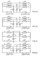
- Figure 3a is a superimposed quantity diagram for a three phase system having perfectly transposed lines and symmetrical sources in which a solid three phase to ground fault has occurred.
- the emf s V'af, V'bf and V'cf of the fault point sources 4, 5 and 6 are as follows:- where Vaf, Vbf and Vcf are the pre-fault phase voltages at the fault point.
- Figure 3b is a superimposed quantity diagram for the same three phase system in which an a-phase to ground fault exists.
- the emf s of fault point sources 4, 5 and 6 are then as follows: and the following relationships exist
- Figure 3c is a superimposed quantity diagram for the same three phase system in which an a-phase to b-phase fault exists.
- the e.m.fs V'abf, V'bcf and V'caf of fault point sources 7, 8 and 9 are then as follows:- where Vabf is the pre-fault fault point voltage between phases a and b.
- this fault can be identified by the occurrence of any of the following conditions at any point on the system.
- Figure 3d is a superimposed quantity diagram for the same system in which an a-phase to b phase to ground fault exists.
- the e.m.fs of fault point sources 4, 5 and 6 are then as follows:- where Zo (1) and Zo (2) are the zero sequence impedances on either side of the fault point.
- condition used for fault identification could be or alternatively where R is any suitable ohmic quantity.
- Figure 4 shows in block schematic form one apparatus for use in a protective relay equipment to control circuit breaker operation wherein identification of faults is effected by a method as described above.
- the input to the apparatus comprises three signals Vi representative of the system phase currents and four signals Vv representative of the system phase and neutral voltages, these signals being produced in conventional manner by current and voltage transducers TDC and TDV e.g. transformers.
- the current and voltage representative signals Vi and Vv are supplied to a fault detector FD which indicates when a fault has occurred in the system e.g. by means of a circuit, such as described in U.K. Patent Specification No. 1,351,417, which produces an output when a rapid vector change occurs in an input Vi or Vv.
- the memory continuously stores samples of the values of inputs Vi and Vv relating to at least the preceding cycle of the system, and may suitably comprise a charge coupled device memory arrangement.
- a logic circuit LCB determines when the circuit breaker (not shown) controlled by the apparatus is opened, the memory MM being cleared when the circuit breaker opens to be ready for further operation if and when the circuit breaker recloses.
- the gate GT On detection of a fault by detector FD the gate GT is operated to supply input signals Vi and Vv to a unit DSPQ instead of to the memory MM via converter AA.
- the unit DSPQ differences the signals Vv and Vi under fault conditions and the pre-fault values of Vv and Vi stored in memory MM to derive the required superimposed quantities I'a, V'a etc required for fault detection.
- fault identification analogue comparator units LG, LLG, LL and 30 ⁇ to which the appropriate superimposed quantities are supplied from unit DSPQ.
- the unit LG identifies phase to ground faults and is thus arranged to produce an output when it detects any of the following conditions: where Oi and ⁇ v have low values such that if not exceeded the relevant compared quantity may be assumed to be zero.
- the unit LL identifies phase to phase faults by producing an output when it detects any of the following conditions:
- the unit 3 ⁇ identifies three phase faults, solid three phase to ground faults, and three phase to ground faults with equal phase to ground fault resistances and/or equal phase to phase fault resistances by producing an output when it detects either of the following conditions:
- the unit LLG identifies phase to phase to ground faults.
- the unit LLG is suitably arranged to produce an output when it detects any of the following conditions: where ⁇ i is a precalculated value for the healthy phase superimposed current during a phase to phase to ground fault in the protected system.
- the angular difference between I'a + I'b etc and In may be used.
- this technique assumes sinusoidal waveforms and hence the unit LLG may require filters to eliminate high frequency and decaying components.
- a high resistance phase to phase to ground fault will generally produce conditions similar to a three phases to ground fault and be detected by unit 3 ⁇ .
- the unit LLG may be dispensed with and any fault detected by FD which is not identified by units LG, LL or 30 assumed to be a two phase to ground fault.
- the output of the fault identification units are fed to a system logic unit SL in which a final decision on determination of fault and operation of circuit breakers is taken.
- the functions performed by the unit SL depend on the particular protective relay scheme in which the apparatus is used and the actual protected system. Thus if LLG is dispensed with, as described above, the unit SL is arranged to assume a two phase to ground fault if the detector FD detects a fault but none of the fault identification units LG, LL and 30 produces an output. Unit SL may also be arranged to assume a three phase fault if two or more fault identification units simultaneously produce outputs.
- system logic unit SL needs to know the particular phase or phases involved in a fault detected by a fault identification unit LG, LL or LLG, such unit may easily be arranged to indicate this to the logic unit SL by indicating which of the various conditions it monitors has been detected.
- a detector unit NI may be provided to indicate when the neutral current In exceeds a predetermined value. This is of particular value for identification of unusual fault conditions such as simultaneous faults or cross country faults.
- the unit SL may also be arranged to take decisions when slowly evolving faults arise.
- identification is inherently high speed since identification commences as soon as the system disturbance produced by a fault has propagated along the system from the fault point to the monitoring, i.e. protective relaying, point. Furthermore the identification of faults from such disturbances i.e. superimposed quantities is performed directly without the quantities going through delay introducing components such as filters, transactors or analogue to digital converters.
Landscapes
- Emergency Protection Circuit Devices (AREA)
Applications Claiming Priority (2)
| Application Number | Priority Date | Filing Date | Title |
|---|---|---|---|
| GB7933571 | 1979-09-27 | ||
| GB7933571 | 1979-09-27 |
Publications (2)
| Publication Number | Publication Date |
|---|---|
| EP0026620A1 true EP0026620A1 (fr) | 1981-04-08 |
| EP0026620B1 EP0026620B1 (fr) | 1984-05-30 |
Family
ID=10508115
Family Applications (1)
| Application Number | Title | Priority Date | Filing Date |
|---|---|---|---|
| EP80303301A Expired EP0026620B1 (fr) | 1979-09-27 | 1980-09-19 | Procédé et appareil pour l'identification de défauts dans des systèmes électriques de transmission de puissance |
Country Status (4)
| Country | Link |
|---|---|
| US (1) | US4390835A (fr) |
| EP (1) | EP0026620B1 (fr) |
| AU (1) | AU539698B2 (fr) |
| DE (1) | DE3068046D1 (fr) |
Cited By (1)
| Publication number | Priority date | Publication date | Assignee | Title |
|---|---|---|---|---|
| CN102005738A (zh) * | 2010-12-15 | 2011-04-06 | 国网电力科学研究院 | 基于电流幅值比例和差流谐波识别非故障相饱和的方法 |
Families Citing this family (16)
| Publication number | Priority date | Publication date | Assignee | Title |
|---|---|---|---|---|
| US4541031A (en) * | 1983-11-21 | 1985-09-10 | Derek W. Moore | Loop fault isolator |
| US4766549A (en) * | 1984-11-30 | 1988-08-23 | Electric Power Research Institute, Inc. | Single-ended transmission line fault locator |
| US4819119A (en) * | 1987-11-12 | 1989-04-04 | General Electric Company | Faulted phase selector for single pole tripping and reclosing schemes |
| US4795983A (en) * | 1988-03-07 | 1989-01-03 | Westinghouse Electric Corp. | Method and apparatus for identifying a faulted phase |
| WO1995024014A2 (fr) * | 1994-02-28 | 1995-09-08 | Abb Power T & D Company Inc. | Systeme de localisation d'un defaut a partir des donnees d'un seul terminal |
| GB2288930B (en) * | 1994-04-25 | 1998-01-21 | Gec Alsthom Ltd | Methods and apparatus for identifying faulted phases on an electric power transmission line |
| GB2375242A (en) * | 2001-05-03 | 2002-11-06 | Alstom | Protecting a section of an electrical power line |
| EP1936393A1 (fr) * | 2006-12-22 | 2008-06-25 | Abb Research Ltd. | Appareil et procédé de mesure d'impédance |
| DE102008043103A1 (de) * | 2008-10-22 | 2010-04-29 | Alstrom Technology Ltd. | Vorrichtung und Verfahren zur Überwachung und/oder Analyse von Rotoren von elektrischen Maschinen im Betrieb |
| US8289665B2 (en) | 2009-07-17 | 2012-10-16 | The Invention Science Fund I Llc | Systems and methods for grounding power line sections to clear faults |
| EP2378296B1 (fr) * | 2010-04-19 | 2016-03-23 | ABB Technology AG | Procédé et agencement pour déterminer des valeurs d'impédance |
| US8941387B2 (en) * | 2010-10-12 | 2015-01-27 | Howard University | Apparatus and method for fault detection and location determination |
| US10763663B2 (en) | 2018-02-27 | 2020-09-01 | Abb Power Grids Switzerland Ag | High speed protection of power transmission lines |
| CN109470992B (zh) * | 2018-10-29 | 2025-02-21 | 中电普瑞科技有限公司 | 一种电力系统线路故障识别方法及装置 |
| CN110912161B (zh) * | 2019-12-12 | 2023-05-12 | 西南交通大学 | 一种牵引变电所电源进线缺相故障判别方法 |
| KR102271830B1 (ko) * | 2020-10-07 | 2021-07-01 | 한화솔루션 주식회사 | 에너지 절감형 잉곳 성장 장치 |
Citations (4)
| Publication number | Priority date | Publication date | Assignee | Title |
|---|---|---|---|---|
| FR1416357A (fr) * | 1964-03-23 | 1965-11-05 | Comp Generale Electricite | Dispositif sélecteur de phase |
| FR2033205A1 (fr) * | 1968-12-10 | 1970-12-04 | English Electric Co Ltd | |
| FR2177467A1 (fr) * | 1972-02-08 | 1973-11-09 | Electricite De France | |
| FR2291632A1 (fr) * | 1974-11-18 | 1976-06-11 | Gen Electric | Relais protecteur pour alimentation alternative |
Family Cites Families (4)
| Publication number | Priority date | Publication date | Assignee | Title |
|---|---|---|---|---|
| FR1501814A (fr) * | 1966-09-12 | 1967-11-18 | Compteurs Comp D | Dispositif permettant la détection ainsi que la mesure de distance des défauts à la terre dans un réseau triphasé avec neutre mise à la terre |
| US4261038A (en) * | 1978-02-28 | 1981-04-07 | National Research Development Corporation | Protection of electrical power supply systems |
| GB2020124B (en) * | 1978-04-27 | 1982-08-25 | Tokyo Shibaura Electric Co | Overcurrent protection |
| US4281386A (en) * | 1979-08-01 | 1981-07-28 | Tokyo Shibaura Denki Kabushiki Kaisha | Systems for detecting faults in electric power systems |
-
1980
- 1980-09-19 EP EP80303301A patent/EP0026620B1/fr not_active Expired
- 1980-09-19 DE DE8080303301T patent/DE3068046D1/de not_active Expired
- 1980-09-24 AU AU62656/80A patent/AU539698B2/en not_active Ceased
- 1980-09-24 US US06/190,268 patent/US4390835A/en not_active Expired - Lifetime
Patent Citations (4)
| Publication number | Priority date | Publication date | Assignee | Title |
|---|---|---|---|---|
| FR1416357A (fr) * | 1964-03-23 | 1965-11-05 | Comp Generale Electricite | Dispositif sélecteur de phase |
| FR2033205A1 (fr) * | 1968-12-10 | 1970-12-04 | English Electric Co Ltd | |
| FR2177467A1 (fr) * | 1972-02-08 | 1973-11-09 | Electricite De France | |
| FR2291632A1 (fr) * | 1974-11-18 | 1976-06-11 | Gen Electric | Relais protecteur pour alimentation alternative |
Non-Patent Citations (1)
| Title |
|---|
| IEEE TRANSACTIONS ON POWER APPARATUS AND SYSTEMS, vol. PAS-97, no. 6, November-December 1978, pages 2104-2112, New York, U.S.A., M. CHAMIA et al.: "Ultra high speed relay for EHV/UHV transmission lines - development, design and application" * |
Cited By (2)
| Publication number | Priority date | Publication date | Assignee | Title |
|---|---|---|---|---|
| CN102005738A (zh) * | 2010-12-15 | 2011-04-06 | 国网电力科学研究院 | 基于电流幅值比例和差流谐波识别非故障相饱和的方法 |
| CN102005738B (zh) * | 2010-12-15 | 2013-11-06 | 国网电力科学研究院 | 基于电流幅值比例和差流谐波识别非故障相饱和的方法 |
Also Published As
| Publication number | Publication date |
|---|---|
| AU6265680A (en) | 1981-04-09 |
| EP0026620B1 (fr) | 1984-05-30 |
| AU539698B2 (en) | 1984-10-11 |
| DE3068046D1 (en) | 1984-07-05 |
| US4390835A (en) | 1983-06-28 |
Similar Documents
| Publication | Publication Date | Title |
|---|---|---|
| EP0026620B1 (fr) | Procédé et appareil pour l'identification de défauts dans des systèmes électriques de transmission de puissance | |
| US7345488B2 (en) | Apparatus and method for determining a faulted phase of a three-phase ungrounded power system | |
| US7319576B2 (en) | Apparatus and method for providing differential protection for a phase angle regulating transformer in a power system | |
| US5783946A (en) | Fault type classification algorithm | |
| EP0316204B1 (fr) | Relais de protection | |
| US20190187201A1 (en) | Method and Device for Detecting Faults in Transmission and Distribution Systems | |
| EP0637865B1 (fr) | Relais différentiel pour transformateur | |
| US5764064A (en) | Method and device for identifying single ground faults | |
| EP0721686B1 (fr) | Procede et appareil de mesure du courant de charge dans un reseau de distribution et de retablissement dudit courant apres une panne | |
| CA1208348A (fr) | Relais ultra-rapide | |
| US5402071A (en) | Ground fault monitoring device for an electrical power distribution system | |
| US4819119A (en) | Faulted phase selector for single pole tripping and reclosing schemes | |
| JP6362569B2 (ja) | 距離継電装置および送電線保護方法 | |
| GB2059201A (en) | Identifying faults in polyphase systems | |
| US6154687A (en) | Modified cosine filters | |
| EP4009460A1 (fr) | Procédé et système pour détecter des défauts dans un réseau triphasé basse tension | |
| Saleh et al. | Ground Fault Protection in Frequency-Selective Grounded Systems Fed by a Single Transformer. | |
| JPH02266817A (ja) | 電力系統保護継電装置 | |
| JPH01264530A (ja) | 地絡回線選択装置 | |
| JPH0515133B2 (fr) | ||
| Kolla | Application of block pulse functions in a polyphase digital distance relay | |
| JPS633536B2 (fr) | ||
| Muchayi | PERFORMANCE OF DIGITAL DISTANCE RELAY ALGORITHMS FOR PROTECTING TRANSFORMER TERMINATED LINES | |
| JPH04236124A (ja) | 高圧配電線の微地絡故障回線の検出方法 | |
| Chan et al. | Power-system digital back-up protection |
Legal Events
| Date | Code | Title | Description |
|---|---|---|---|
| PUAI | Public reference made under article 153(3) epc to a published international application that has entered the european phase |
Free format text: ORIGINAL CODE: 0009012 |
|
| AK | Designated contracting states |
Designated state(s): CH DE FR SE |
|
| 17P | Request for examination filed |
Effective date: 19811005 |
|
| RAP1 | Party data changed (applicant data changed or rights of an application transferred) |
Owner name: THE GENERAL ELECTRIC COMPANY, P.L.C. |
|
| GRAA | (expected) grant |
Free format text: ORIGINAL CODE: 0009210 |
|
| AK | Designated contracting states |
Designated state(s): CH DE FR LI SE |
|
| REF | Corresponds to: |
Ref document number: 3068046 Country of ref document: DE Date of ref document: 19840705 |
|
| ET | Fr: translation filed | ||
| PGFP | Annual fee paid to national office [announced via postgrant information from national office to epo] |
Ref country code: FR Payment date: 19840730 Year of fee payment: 5 |
|
| PGFP | Annual fee paid to national office [announced via postgrant information from national office to epo] |
Ref country code: CH Payment date: 19840814 Year of fee payment: 5 |
|
| PGFP | Annual fee paid to national office [announced via postgrant information from national office to epo] |
Ref country code: SE Payment date: 19840930 Year of fee payment: 5 |
|
| PGFP | Annual fee paid to national office [announced via postgrant information from national office to epo] |
Ref country code: DE Payment date: 19841126 Year of fee payment: 5 |
|
| PLBE | No opposition filed within time limit |
Free format text: ORIGINAL CODE: 0009261 |
|
| STAA | Information on the status of an ep patent application or granted ep patent |
Free format text: STATUS: NO OPPOSITION FILED WITHIN TIME LIMIT |
|
| 26N | No opposition filed | ||
| PG25 | Lapsed in a contracting state [announced via postgrant information from national office to epo] |
Ref country code: SE Effective date: 19860920 |
|
| PG25 | Lapsed in a contracting state [announced via postgrant information from national office to epo] |
Ref country code: LI Effective date: 19860930 Ref country code: CH Effective date: 19860930 |
|
| PG25 | Lapsed in a contracting state [announced via postgrant information from national office to epo] |
Ref country code: FR Free format text: LAPSE BECAUSE OF NON-PAYMENT OF DUE FEES Effective date: 19870527 |
|
| REG | Reference to a national code |
Ref country code: CH Ref legal event code: PL |
|
| PG25 | Lapsed in a contracting state [announced via postgrant information from national office to epo] |
Ref country code: DE Effective date: 19870602 |
|
| REG | Reference to a national code |
Ref country code: FR Ref legal event code: ST |
|
| EUG | Se: european patent has lapsed |
Ref document number: 80303301.8 Effective date: 19870812 |