EP0026626A2 - Autonomes Navigationssystem - Google Patents
Autonomes Navigationssystem Download PDFInfo
- Publication number
- EP0026626A2 EP0026626A2 EP80303325A EP80303325A EP0026626A2 EP 0026626 A2 EP0026626 A2 EP 0026626A2 EP 80303325 A EP80303325 A EP 80303325A EP 80303325 A EP80303325 A EP 80303325A EP 0026626 A2 EP0026626 A2 EP 0026626A2
- Authority
- EP
- European Patent Office
- Prior art keywords
- vehicle
- signals
- axis
- pendulum
- proportional
- Prior art date
- Legal status (The legal status is an assumption and is not a legal conclusion. Google has not performed a legal analysis and makes no representation as to the accuracy of the status listed.)
- Granted
Links
Images

Classifications
-
- G—PHYSICS
- G01—MEASURING; TESTING
- G01C—MEASURING DISTANCES, LEVELS OR BEARINGS; SURVEYING; NAVIGATION; GYROSCOPIC INSTRUMENTS; PHOTOGRAMMETRY OR VIDEOGRAMMETRY
- G01C21/00—Navigation; Navigational instruments not provided for in groups G01C1/00 - G01C19/00
- G01C21/10—Navigation; Navigational instruments not provided for in groups G01C1/00 - G01C19/00 by using measurements of speed or acceleration
- G01C21/12—Navigation; Navigational instruments not provided for in groups G01C1/00 - G01C19/00 by using measurements of speed or acceleration executed aboard the object being navigated; Dead reckoning
- G01C21/16—Navigation; Navigational instruments not provided for in groups G01C1/00 - G01C19/00 by using measurements of speed or acceleration executed aboard the object being navigated; Dead reckoning by integrating acceleration or speed, i.e. inertial navigation
- G01C21/166—Mechanical, construction or arrangement details of inertial navigation systems
-
- G—PHYSICS
- G01—MEASURING; TESTING
- G01C—MEASURING DISTANCES, LEVELS OR BEARINGS; SURVEYING; NAVIGATION; GYROSCOPIC INSTRUMENTS; PHOTOGRAMMETRY OR VIDEOGRAMMETRY
- G01C21/00—Navigation; Navigational instruments not provided for in groups G01C1/00 - G01C19/00
- G01C21/10—Navigation; Navigational instruments not provided for in groups G01C1/00 - G01C19/00 by using measurements of speed or acceleration
- G01C21/12—Navigation; Navigational instruments not provided for in groups G01C1/00 - G01C19/00 by using measurements of speed or acceleration executed aboard the object being navigated; Dead reckoning
- G01C21/16—Navigation; Navigational instruments not provided for in groups G01C1/00 - G01C19/00 by using measurements of speed or acceleration executed aboard the object being navigated; Dead reckoning by integrating acceleration or speed, i.e. inertial navigation
- G01C21/183—Compensation of inertial measurements, e.g. for temperature effects
Definitions
- the invention relates to autonomous navigation systems in the form of apparatus for measuring local level specific force components on a vehicle, more particularly those utilizing inertial instrumentation.
- inertial navigation systems are based on measurement and double integration of the linear accelerations of the vehicle.
- a plurality of orthogonally disposed accelerometers are mounted on a gyro- scopically stabilized platform that is supported by three, four or even five gimbals.
- a key element in the development of this inertial system has been the stabilized platform on which the accelerometers are mounted and whose attitude is controlled by the gyroscopes.
- the platform performs two critical functions. It establishes a co-ordinate system for the accelerometers and isolates them from angular motions of the vehicle. The first function simplifies navigation computations while the second simplifies computations as well as sensor design.
- the accelerometers must be precisely horizontally aligned.
- a plurality of orthogonally displaced gyros and a plurality of orthogonally aligned accelerometers are strapped directly to the airframe.
- the stable platform is replaced by two computer functions: one to establish a co-ordinate reference based on the gyro outputs and the other to transform the accelerometer outputs into the established co - ordinate frame.
- the strapdown sensor must operate to the same order of accuracy as its platform counterpart.
- the angular.rate regime for the strapdown sensor is in deg/sec instead of the deg/hr category for a stable platform sensor.
- the major design impact is of course on the gyro rather than the accelerometer, as the former must measure the rates very precisely.
- the dynamic range for the gyro could, for example, begin at a threshold of 0.01 deg/hr and extend to the area of 100 deg/sec or so, for a span of about 10 7 compared with a 10 4 span in gimballed platforms.
- This invention involves an unbalanced, pendulous, two-axis gimbal system wherein the outer gimbal is strapped to the longitudinal axis of the vehicle and the inner gimbal supports a two-degree of freedom levelling gyroscope and a heading gyroscope.
- the rate signals measured by the levelling gyroscope are integrated, amplified and fed to gimbal torquers.
- the axis of the pendulum is maintained coincident with the local vertical and the outputs of the amplifiers are proportional to the longitudinal and lateral vehicular specific forces in the locally level plane irrespective of vehicle pitch, roll and yaw motions.
- the specific force components in the locally level co-ordinate system are converted to components in the geographical co-ordinate system by means of a single Euler transformation.
- the standard navigation equations are solved to determine longitudinal and lateral velocities in the geographical co-ordinate system, and finally vehicle position is determined by a further integration.
- Vehicle velocity, altitude, position and attitude measurements can be simultaneously presented on a display.
- the heading gyroscope is calibrated simply and quickly with a single resolver operation.
- the gyroscopic inertial measurement unit provides a stable and accurate local vertical reference that is insensitive to accleration and roll, pitch and yaw motions.
- This invention provides an improved low-cost autonomous navigation system that departs from conventional gimballed and strapdown inertial systems.
- Among its advantages are that it provides a stable acceleration-insensitive accurate local vertical reference; that it provides longitudinal and lateral vehicular specific force measurements in the locally level plane irrespective of the vehicle pitch, roll and yaw motions; that it provides longitudinal and lateral velocities in locally level geographic co-ordinates along with vehicle position, altitude and attitude information; that it minimizes the number of sensors and the system complexity and thus reduces errors and alignment procedures; and that it provides a simple and rapid north calibration procedure.
- GIMU gyroscopic inertial measurement unit 6 of the present invention is depicted schematically and perspectively in FIG. 1.
- An outer gimbal 7 with shafts 15 is rotatably supported in bearings 10 which are secured to aircraft frame 11.
- the rotors of torque generator 8 and signal generator 9 are secured to shafts 15.
- the aircraft in which the GIMU 6 is utilized has an orthogonal co-ordinate frame x b , y b , z b wherein x b , y b and z b represent the roll, pitch and yaw axes, respectively.
- Gimbal axis 12 is positioned coaxially with axis x b (the longitudinal and roll axis of the aircraft).
- the axis of rotation 17 of inner gimbal 13 is normal to outer gimbal axis 12.
- Each gimbal shaft 20 has an end secured to gimbal 13 and an end rotatably supported in a bearing (not illustrated) in gimbal 12.
- the rotors of signal generator 16 and torque generator 14 are fastened to shafts 20 and the stators of these generators are secured to gimbal 7. It is desirable that the gimbal bearings be of the low friction class and that torque generators 8 and 14 be relatively powerful torquers thathave as much torque capacity as those typically found in vertical gyroscopes.
- Signal generators 9 and 16 may be, for example, low-friction synchro-type pick-off generators.
- the signal on output 18 of signal generator 9 is representative of the aircraft roll angle t. As will become clearer later, the signal of output 19 of signal generator 16 is representative of the aircraft pitch angled .
- Gyroscopes 21 and 22 and mass M are secured to inner gimbal 13 and disposed along a common axis 23 which is normal to axis 17 and passes through point 24, the point where axes 12 and 17 intersect.
- gyroscope 22 is shown between gyroscope 21 and mass M, it is to be understood that the positions of gyroscopes 21 and 22 may be interchanged.
- the centre of gravity of the combination comprising gimbals 12, 13 gyroscopes 21, 22 and mass M is below axis intersection point 24.
- the combination acts as a two-axis pendulum 25 and a servo system maintains the pendulum axis coincident with the local vertical.
- Gyroscope 22 is a two-degree-of-freedom gyroscope having two rate signal outputs, two torquers and a rotor with a spin axis coaxial with axis 23. It is hereinafter referred to as the levelling gyroscope and gyroscope 21 is called the azimuth gyroscope. Signals ⁇ and ⁇ are generated at outputs 26 and 27, respectively.
- Torque compensation signals T ⁇ and T ⁇ are applied to gyro torquer input terminals 28 and 29 respectively.
- Gyroscope 21 is a one-degree-of-freedom gyroscope with a torquer, a rate signal output and a rotor with a spin axis orthogonal to axis 23.
- a torque compensation signal T ⁇ is applied to torquer input terminal 31 and a pick-off signal ⁇ is developed at gyro terminal output 32 and coupled to the input of integrator 33.
- a heading signal ⁇ o is inputed to the integrator via lead 55 and establishes the initial value of the heading measurement.
- the output of amplifier 33 is proportional to heading angle ⁇ ,, the angle subtended between axis x l and true north (N).
- gyroscope 21 requires a larger angular rate-regime than gyroscope 22.
- gyroscope 21 need not have as low a drift rate as gyroscope 22.
- gyroscopes 21 and 22 will be of the dry-tuned-rotor (DTR) variety.
- DTR gyros normally have two rate signal outputs and two torquers. Thus, if a DTR gyro is used for gyroscope 21, the second signal output and second torquer will not be utilized. Dry-tuned-rotor gyroscopes are described, for example, in the following articles:
- the gyro output signal n developed at terminal 26 is fed through switch 36, integrated in integrator 37 and amplified by summing amplifier 38.
- the output of amplifier 38 is connected to torquer generator 14 and other circuitry that will be discussed below.
- gyro output signal ⁇ is fed through a switch 41, is integrated in integrator 42 and amplified in summing amplifier 43.
- the amplifier output is coupled to torque generator 8 and other circuitry that will be described later.
- the other inputs of amplifiers 38 and 43 receive nulling/compensation signals n x and n y , respectively from circuit 51.
- the gyroscopic inertial measurement unit 6 performs as a two-axis horizontally stabilized specific force sensor capable of measuring locally level force components irrespective of the vehicle body axis system orientation. These force components, when further processed, enable the determination of the vehicle's velocity and position, in geographical co-ordinates, in real time.
- the axis disturbances excite gyro output signals in terminals 26 and 27 that are representative of n and ⁇ , respectively.
- Signal ⁇ is integrated in integrator 37 and amplified in amplifier 38.
- the amplifier output energizes torquer 14 and moves the inner gimbal structure so as to bring ⁇ to zero.
- signal is integrated in integrator 42 and amplified in gain amplifier 43.
- the amplifier output signal energizes torque generator 8 and causes the two-axis gimbal assembly to rotate about axis x b to reduce ⁇ to zero.
- the output of amplifier 38, signal F xGc (standing for specific force along the x axis of the GIMU co-ordinate frame), is proportional to F xl .
- output signal F yGc fromanplifier 43 is proportional to specific force F yl . . Inasmuch as the servos keep pendulum axis 23 aligned with axis Z l , vertical force F ze does not exert a torque on the pendulum and it is not measured.
- the angular displacement between aircraft axis x b and X e is pitch angle e and it is measured by signal generator 16.
- the pitch angle and other measured parameters may be viewed on display 75.
- the angle between aircraft axis y b and Y e represents the roll angle ⁇ of the aircraft and it is measured by signal generator 9 and indicated on display 75.
- the typical prior art vertical gyro has erection sensors that cannot distinguish between gyro tilt and horizontal acceleration. These gyros are usually disabled during aircraft turns to avoid large acceleration-dependent : drift rates.
- the pitch and roll measurements of the aircraft co-ordinate system are precise and acceleration insensitive.
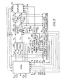
- FIGURE 2 depicts a complete diagram of the instant navigation system.
- the GIMU signals F yGc and F xGc corresponding to the y and x specific force components in the GIMU local level co-ordinate frame are inputed to a co-ordinate converter 66 along with heading signal ⁇ .
- the co-ordinate converter performs a single conventional Euler angle transformation to convertthe local level co-ordinate system specific force components to force components in a geographical co-ordinate frame comprising north (N), east (E) and vertical axes.
- converter 66 performs the following transformation:
- a signal V V representative of the vertical velocity of the aircraft is developed by an altimeter/differentiator combination.
- An altitude signal h is generated by altimeter 67, differentiated by differentiator 68 and fed to 69 along with converter output signals F E and F N and a signal ⁇ , representative of latitude, generated by circuit 51.
- Circuit 69 generates signals V N and V E representative of the velocity of the aircraft along the north (N) and east (E) geographical axes. It does so by integrating the standard navigation equations for V N and V E .
- One of the many places where these equations are found is page 75 of Integrated Aircraft Navigation, James L. Farrell, Academic Press, 1976.
- Velocity signals V E and V N are integrated by integrators 73 and 74, respectively, producing geographical position signals Y G and X G , respectively.
- Y G is the position of the aircraft on the east-west or Y axis of the geographical co-ordinate frame
- X G is the position of the aircraft on the north-south or X axis of the co-ordinate frame.
- Signals representative of the initial aircraft geographical co-ordinates are applied to the integrators at terminals 85 and 86.
- the ⁇ , ⁇ , and signals are carried from GIMU 6 to display 75 by leads 77, 78 and 79, respectively.
- the roll, pitch and heading of the aircraft are presented on display 75 along with aircraft velocities VE, V N , aircraft positions Y G , X G , and altitude h.
- N geographical north
- the north calibration process is initiated on the ground with switches 36 and 41 open. This of course deactivates the servo loops that position pendulum 25. With the torquers 8 and 14 deactivated, pendulum axis 23 quickly seeks alignment with Z e . Due to the rotation of the earth, ⁇ and ⁇ signals are generated at the outputs of levelling gyroscope 22.
- reaction torques resulting from the earth's rotation in the order of 10 -3 gram-cm
- torques resulting from gimbal bearing friction in the order of 0.05 gram-cm
- Resolver and drift rate calibrator 57 permits the accurate determination of true-north (N) with respect to the instant direction of the longitudinal axis x e , i.e. ⁇ o , and determines turn on-to turn on drift rate signals ⁇ d , ⁇ d , and ⁇ d .. Signals and ⁇ are inputed to circuit 57 from GIMU 6. In addition, circuit 57 receives a ⁇ i signal from generator 63 on lead 64 and a signal proportional to latitude, ⁇ , from circuit 51.
- the ⁇ o signal is routed to tuning and compensation circuit 51 on lead 80.
- the signal receives a compensation factor that accounts for the drift of azimuth gyroscope 21.
- the compensated ⁇ o signal reaches GIMU 6 via lead 55.
- switches 36 and 41 are closed. Signals F xGc and F yGc should each be zero at the time of calibration.
- circuit 51 Signals n x and n y , developed in circuit 51 and carried to amplifiers 38 and 43 via leads 61 'and 6'2, respectively, null out any unwanted output signals. Furthermore, during flight, circuit 51 generates a signal on lead 61 that compensates for unwanted reaction torques of gyroscope 21 in consequence of yaw rate This compensation signal is proportional to the product of the known values and the angular momentum of gyroscope 21.
- any subsequent azimuth change of the aircraft (and the GIMU which is hinged thereto) will cause gyroscope 21 to generate a heading rate signal ⁇ at output 32.
- Signal ⁇ is integrated by integrator 33 and the heading of the aircraft is constantly monitored on display 75 which is coupled to the out put of integrator 33 via lead 79.
- the inputs to 51 for determining the Schuler tuning signals are V E , V N and ⁇ with g, the gravity constant and R E , the radius of the earth, as known parameters.
- pendulum 25 acts as a Schuler pendulum and maintains the local vertical throughout the entire flight mission.
- signals T ⁇ , T ⁇ and T ⁇ repzesent the collective compensatory torque command signals generated by 51 and transmitted to the azimuth and levelling gyroscopes via leads 52-54. That is, the Schuler tuning signals are summed with the drift rate compensation signals, etc.
- the inputs to 51 for determining gyro acceleration sensitivity compensation signals are F yGc and F xGc with the gyro acceleration drift rate-sensitivity co-efficients as known compensation parameters.
- the drift rates for gyroscope 22 are determined by:
- the azimuth gyroscope 21 is subjected to the earth rate component ⁇ sin ⁇ whersin ⁇ is the sideral rate of rotation of the earth and ⁇ is latitude.
- the drift rate signals ⁇ d , ⁇ d and ⁇ d produced in calibrator 57 are carried to circuit 51 by leads 81,' 82 and 83, respectively. These signals are scaled in circuit 51 to provide drift rate compensation torque command signals that are fed to GIMU 6 via leads 52, 53 and 54.
- the latitude signal ⁇ for resolver/calibrator 57 and integrator 69 is generated in circuit 51 by solving wherein V N is acquired from circuit 69 and R is the distance of the vehicle from the centre of the earth (R E +h).
- the computations performed by circuits 51, 57, 66, 69, 73 and 74 are preferably performed by a digital computer such as a microprocessor or a minicomputer.
- the torques due to gimbal bearing friction can be readily modelled and appropriate compensating torque command signals can be generated and applied to the gimbal torquers.
- a periodical dither signal of a frequency of approximately 5 Hz can be applied to the levelling gyroscope torquers to linearize the output characteristics.
- the angularamplitude resulting from the dither signal would be in the order of a few mRad.
- the instant navigation system has a multiplicity of advantages over conventional autonomous navigation systems. Inasmuch as only two gyroscopes and no accelerometers or stable platforms are required in the system, substantial savings in cost and instrumentation package size are achieved. In a strapdown type inertial navigation system all the gyroscopes and accelerometers must be of high quality and a high speed, large memory digital computer is necessary to perform the many integrations and transformations. Herein, any one of a number of off-the-shelf low cost microprocessors can be utilized to perform all the transformations, integrations and compensations.
- the azimuth gyroscope 21 can have a drift rate uncertainty of the order of ten times as large as that of levelling gyroscope 22.
- gyroscope 21 and 22 should have random drift rates not more than 0.1 deg/hr and 0.01 deg/hr. respectively.
- the dominant error of the system primarily stems from a single source and the errors attributable to that source are basically drift rate and initial levelling errors. This improves null point precision.
- the essential specific force components F xGc and Fy Gc are derived from a single sensor (gyroscope 22)
- the difficulties associated with mechanical alignments of accelerometer and gyroscope triads are obviated.
- the spin axis of gyroscope 22 is always maintained vertical, the GIMU is insensitive to yaw motions. Because no accelerometers are present in the GIMU, bias errors due to correlated noise signals in the gyros and accelerometers are avoided.
- true north is determined by a relatively time consuming gyro-compassing process.
- a typical strapdown or gimballed system it is not unusual to spend in the order of fifteen minutes performing the north calibration.
- the determination of true north is essentially instantaneous by virtue of'the rapid levelling of the open loop pendulous system.
Landscapes
- Engineering & Computer Science (AREA)
- Radar, Positioning & Navigation (AREA)
- Remote Sensing (AREA)
- Automation & Control Theory (AREA)
- Physics & Mathematics (AREA)
- General Physics & Mathematics (AREA)
- Navigation (AREA)
Applications Claiming Priority (2)
| Application Number | Priority Date | Filing Date | Title |
|---|---|---|---|
| US78611 | 1979-09-24 | ||
| US06/078,611 US4244215A (en) | 1979-09-24 | 1979-09-24 | Autonomous navigation system |
Publications (3)
| Publication Number | Publication Date |
|---|---|
| EP0026626A2 true EP0026626A2 (de) | 1981-04-08 |
| EP0026626A3 EP0026626A3 (en) | 1982-05-12 |
| EP0026626B1 EP0026626B1 (de) | 1986-03-12 |
Family
ID=22145154
Family Applications (1)
| Application Number | Title | Priority Date | Filing Date |
|---|---|---|---|
| EP80303325A Expired EP0026626B1 (de) | 1979-09-24 | 1980-09-23 | Autonomes Navigationssystem |
Country Status (5)
| Country | Link |
|---|---|
| US (1) | US4244215A (de) |
| EP (1) | EP0026626B1 (de) |
| JP (1) | JPS5696212A (de) |
| CA (1) | CA1141008A (de) |
| DE (1) | DE3071485D1 (de) |
Cited By (2)
| Publication number | Priority date | Publication date | Assignee | Title |
|---|---|---|---|---|
| EP0077378B1 (de) * | 1981-04-28 | 1986-12-03 | MATTHEWS, Robert J. | Mechanisch stabilisiertes plattform-system |
| DE102005042741A1 (de) * | 2005-09-02 | 2007-06-06 | Vladimir Belenkiy | Verfahren zur Erarbeitung einer Navigationsinformation durch ein Inertialsystem |
Families Citing this family (32)
| Publication number | Priority date | Publication date | Assignee | Title |
|---|---|---|---|---|
| US5001647A (en) * | 1989-08-31 | 1991-03-19 | General Electric Company | Inertial transformation matrix generator |
| US5357817A (en) * | 1990-04-19 | 1994-10-25 | Charles Stark Draper Laboratory, Inc. | Wide bandwidth stable member without angular accelerometers |
| US5194872A (en) * | 1990-11-14 | 1993-03-16 | Charles Stark Draper Laboratory, Inc. | Inertial navigation system with automatic redundancy and dynamic compensation of gyroscope drift error |
| RU2117300C1 (ru) * | 1997-02-21 | 1998-08-10 | Ракетно-космическая корпорация "Энергия" им.С.П.Королева | Система определения кинематических параметров движения (варианты) |
| US6389333B1 (en) * | 1997-07-09 | 2002-05-14 | Massachusetts Institute Of Technology | Integrated flight information and control system |
| GR980100376A (el) * | 1998-10-15 | 2000-06-30 | Αυτονομο συστημα προσδιορισμου στιγματος παγκοσμιου εμβελειας | |
| US7740099B2 (en) | 1999-06-04 | 2010-06-22 | Segway Inc. | Enhanced control of a transporter |
| EP1190283B1 (de) | 1999-06-30 | 2005-04-06 | Deka Products Limited Partnership | Vorrichtung und verfahren zum abschätzen des nickneigungszustandes eines personengebundenen fahrzeuges |
| US20040221762A1 (en) * | 2003-05-06 | 2004-11-11 | Lockheed Martin Corporation | Inertial measurement unit based levitation control |
| US7274439B2 (en) * | 2004-09-10 | 2007-09-25 | Honeywell International Inc. | Precise, no-contact, position sensing using imaging |
| US7289902B2 (en) * | 2004-09-10 | 2007-10-30 | Honeywell International Inc. | Three dimensional balance assembly |
| US7340344B2 (en) * | 2004-09-10 | 2008-03-04 | Honeywell International Inc. | Spherical position monitoring system |
| US7458264B2 (en) * | 2004-09-10 | 2008-12-02 | Honeywell International Inc. | Generalized inertial measurement error reduction through multiple axis rotation during flight |
| US7698064B2 (en) * | 2004-09-10 | 2010-04-13 | Honeywell International Inc. | Gas supported inertial sensor system and method |
| US7617070B2 (en) * | 2004-09-10 | 2009-11-10 | Honeywell International Inc. | Absolute position determination of an object using pattern recognition |
| US20060054660A1 (en) * | 2004-09-10 | 2006-03-16 | Honeywell International Inc. | Articulated gas bearing support pads |
| US7295947B2 (en) * | 2004-09-10 | 2007-11-13 | Honeywell International Inc. | Absolute position determination of an object using pattern recognition |
| US7366613B2 (en) * | 2004-09-10 | 2008-04-29 | Honeywell International Inc. | RF wireless communication for deeply embedded aerospace systems |
| KR100666160B1 (ko) | 2004-12-29 | 2007-01-09 | 한국항공우주연구원 | 궤도기하학을 이용한 인공위성 자기센서의 바이어스보정방법 |
| US6961643B1 (en) * | 2005-02-02 | 2005-11-01 | Tru Trak Flight Systems, Inc | System and method for gyro enhanced vertical flight information |
| US7295135B2 (en) * | 2006-02-06 | 2007-11-13 | Trutrak Flight Systems, Inc. | Flight information system |
| US20080039991A1 (en) * | 2006-08-10 | 2008-02-14 | May Reed R | Methods and systems for providing accurate vehicle positioning |
| US7979179B2 (en) * | 2006-08-11 | 2011-07-12 | Segway Inc. | Apparatus and method for pitch state estimation for a vehicle |
| KR101406469B1 (ko) | 2006-08-11 | 2014-06-13 | 세그웨이 아이엔씨. | 전기 운송수단의 속도 제한 |
| US7647176B2 (en) * | 2007-01-11 | 2010-01-12 | Honeywell International Inc. | Method and system for wireless power transfers through multiple ports |
| US7762133B2 (en) * | 2007-07-17 | 2010-07-27 | Honeywell International Inc. | Inertial measurement unit with gas plenums |
| US7425097B1 (en) | 2007-07-17 | 2008-09-16 | Honeywell International Inc. | Inertial measurement unit with wireless power transfer gap control |
| US20090055033A1 (en) * | 2007-08-23 | 2009-02-26 | Segway Inc. | Apparatus and methods for fault detection at vehicle startup |
| US7671607B2 (en) * | 2007-09-06 | 2010-03-02 | Honeywell International Inc. | System and method for measuring air bearing gap distance |
| IL222221B (en) * | 2012-09-27 | 2019-03-31 | Rafael Advanced Defense Systems Ltd | Improved system and method for inertial navigation |
| CN106525030B (zh) * | 2015-09-10 | 2019-08-02 | 中国航空工业第六一八研究所 | 一种导航系统双余度控制和显示的方法 |
| RU2017133806A (ru) * | 2017-09-28 | 2019-03-28 | Акционерное общество "НЕОЛАНТ" | Способ сбора данных и система для осуществления указанного способа |
Family Cites Families (7)
| Publication number | Priority date | Publication date | Assignee | Title |
|---|---|---|---|---|
| US2811043A (en) * | 1954-06-21 | 1957-10-29 | Honeywell Regulator Co | Vertical reference and acceleration apparatus |
| US2770452A (en) * | 1954-11-26 | 1956-11-13 | Sperry Rand Corp | System for measuring the acceleration of a dirigible craft |
| US3077783A (en) * | 1959-03-24 | 1963-02-19 | Gen Precision Inc | Two-axis accelerometer |
| US3071008A (en) * | 1959-08-20 | 1963-01-01 | Litton Systems Inc | Acceleration measuring system |
| DE2224535A1 (de) * | 1972-05-19 | 1973-11-29 | Deutsche Forsch Luft Raumfahrt | Bordautonomes hybrid-navigationssystem |
| US3931747A (en) * | 1974-02-06 | 1976-01-13 | Sperry Rand Corporation | Gyroscopic stable reference device |
| US3979090A (en) * | 1975-03-17 | 1976-09-07 | Sperry Rand Corporation | Velocity damped erection system for stable gyroscopic attitude and heading reference apparatus |
-
1979
- 1979-09-24 US US06/078,611 patent/US4244215A/en not_active Expired - Lifetime
-
1980
- 1980-09-22 JP JP13222280A patent/JPS5696212A/ja active Pending
- 1980-09-23 EP EP80303325A patent/EP0026626B1/de not_active Expired
- 1980-09-23 DE DE8080303325T patent/DE3071485D1/de not_active Expired
- 1980-09-23 CA CA000360794A patent/CA1141008A/en not_active Expired
Cited By (2)
| Publication number | Priority date | Publication date | Assignee | Title |
|---|---|---|---|---|
| EP0077378B1 (de) * | 1981-04-28 | 1986-12-03 | MATTHEWS, Robert J. | Mechanisch stabilisiertes plattform-system |
| DE102005042741A1 (de) * | 2005-09-02 | 2007-06-06 | Vladimir Belenkiy | Verfahren zur Erarbeitung einer Navigationsinformation durch ein Inertialsystem |
Also Published As
| Publication number | Publication date |
|---|---|
| JPS5696212A (en) | 1981-08-04 |
| EP0026626B1 (de) | 1986-03-12 |
| US4244215A (en) | 1981-01-13 |
| EP0026626A3 (en) | 1982-05-12 |
| DE3071485D1 (en) | 1986-04-17 |
| CA1141008A (en) | 1983-02-08 |
Similar Documents
| Publication | Publication Date | Title |
|---|---|---|
| EP0026626B1 (de) | Autonomes Navigationssystem | |
| US4038527A (en) | Simplified strapped down inertial navigation utilizing bang-bang gyro torquing | |
| US7216055B1 (en) | Dynamic attitude measurement method and apparatus | |
| US7418364B1 (en) | Dynamic attitude measurement method and apparatus | |
| US6853947B1 (en) | Dynamic attitude measurement method and apparatus | |
| CA1277401C (en) | Method for determining the heading of an aircraft | |
| US2914763A (en) | Doppler-inertial navigation data system | |
| US3597598A (en) | Method and means for transforming the acceleration signals generated by accelerometers in a first coordinate system into acceleration signals in a second coordinate system | |
| US2968957A (en) | Centripetal acceleration compensation computer for stable platform | |
| US3414899A (en) | Apparatus for calibrating doppler-inertial navigation systems | |
| US3241363A (en) | Navigation instruments | |
| US4275605A (en) | Acceleration sensitive gyroscope stabilized platform | |
| US4085440A (en) | Inertial navigation system | |
| Huddle | Trends in inertial systems technology for high accuracy AUV navigation | |
| US20080010017A1 (en) | Method For Elaborating Navigation Parameters And Vertical Of A Place | |
| US3131292A (en) | Coordinate reference system | |
| US4180916A (en) | Gyroscopic instruments | |
| GB2056062A (en) | Attitude and Reading Reference System and Inertial Navigation System Based on Gyroscopic Pendulums | |
| US4675822A (en) | Doppler-inertial data loop for navigation system | |
| US3430238A (en) | Apparatus for providing an accurate vertical reference in a doppler-inertial navigation system | |
| US3232103A (en) | Navigation system | |
| US3214983A (en) | Attitude reference | |
| Merhav | Autonomous navigation system | |
| CA1167669A (en) | Inertial platforms | |
| US3352164A (en) | Gyro monitor adaptive mechanization |
Legal Events
| Date | Code | Title | Description |
|---|---|---|---|
| PUAI | Public reference made under article 153(3) epc to a published international application that has entered the european phase |
Free format text: ORIGINAL CODE: 0009012 |
|
| AK | Designated contracting states |
Designated state(s): CH DE FR GB NL SE |
|
| PUAL | Search report despatched |
Free format text: ORIGINAL CODE: 0009013 |
|
| AK | Designated contracting states |
Designated state(s): CH DE FR GB NL SE |
|
| 17P | Request for examination filed |
Effective date: 19820720 |
|
| GRAA | (expected) grant |
Free format text: ORIGINAL CODE: 0009210 |
|
| AK | Designated contracting states |
Kind code of ref document: B1 Designated state(s): CH DE FR GB LI NL SE |
|
| REF | Corresponds to: |
Ref document number: 3071485 Country of ref document: DE Date of ref document: 19860417 |
|
| ET | Fr: translation filed | ||
| PLBE | No opposition filed within time limit |
Free format text: ORIGINAL CODE: 0009261 |
|
| STAA | Information on the status of an ep patent application or granted ep patent |
Free format text: STATUS: NO OPPOSITION FILED WITHIN TIME LIMIT |
|
| 26N | No opposition filed | ||
| PGFP | Annual fee paid to national office [announced via postgrant information from national office to epo] |
Ref country code: NL Payment date: 19870930 Year of fee payment: 8 |
|
| PG25 | Lapsed in a contracting state [announced via postgrant information from national office to epo] |
Ref country code: GB Effective date: 19880923 |
|
| PG25 | Lapsed in a contracting state [announced via postgrant information from national office to epo] |
Ref country code: SE Effective date: 19880924 |
|
| PG25 | Lapsed in a contracting state [announced via postgrant information from national office to epo] |
Ref country code: LI Effective date: 19880930 Ref country code: CH Effective date: 19880930 |
|
| PG25 | Lapsed in a contracting state [announced via postgrant information from national office to epo] |
Ref country code: NL Effective date: 19890401 |
|
| NLV4 | Nl: lapsed or anulled due to non-payment of the annual fee | ||
| PG25 | Lapsed in a contracting state [announced via postgrant information from national office to epo] |
Ref country code: FR Free format text: LAPSE BECAUSE OF NON-PAYMENT OF DUE FEES Effective date: 19890531 |
|
| REG | Reference to a national code |
Ref country code: CH Ref legal event code: PL |
|
| GBPC | Gb: european patent ceased through non-payment of renewal fee | ||
| PG25 | Lapsed in a contracting state [announced via postgrant information from national office to epo] |
Ref country code: DE Effective date: 19890601 |
|
| REG | Reference to a national code |
Ref country code: FR Ref legal event code: ST |
|
| EUG | Se: european patent has lapsed |
Ref document number: 80303325.7 Effective date: 19890614 |