EP0026689A2 - Anhebbares Hauptfahrwerk für Fahrzeug - Google Patents
Anhebbares Hauptfahrwerk für Fahrzeug Download PDFInfo
- Publication number
- EP0026689A2 EP0026689A2 EP80401281A EP80401281A EP0026689A2 EP 0026689 A2 EP0026689 A2 EP 0026689A2 EP 80401281 A EP80401281 A EP 80401281A EP 80401281 A EP80401281 A EP 80401281A EP 0026689 A2 EP0026689 A2 EP 0026689A2
- Authority
- EP
- European Patent Office
- Prior art keywords
- axis
- jack
- connecting rod
- point
- leg
- Prior art date
- Legal status (The legal status is an assumption and is not a legal conclusion. Google has not performed a legal analysis and makes no representation as to the accuracy of the status listed.)
- Granted
Links
Images

Classifications
-
- B—PERFORMING OPERATIONS; TRANSPORTING
- B64—AIRCRAFT; AVIATION; COSMONAUTICS
- B64C—AEROPLANES; HELICOPTERS
- B64C25/00—Alighting gear
- B64C25/02—Undercarriages
- B64C25/08—Undercarriages non-fixed, e.g. jettisonable
- B64C25/10—Undercarriages non-fixed, e.g. jettisonable retractable, foldable, or the like
- B64C25/14—Undercarriages non-fixed, e.g. jettisonable retractable, foldable, or the like fore-and-aft
Definitions
- the subject of the invention is a liftable undercarriage for a vehicle, in particular for an aerodyne, such as for example helicopters.
- each undercarriage includes a leg, the box of which is articulated, around a fixed lifting axis on the structure of the aerodyne, and a breaker strut , consisting of a connecting rod, articulated around a fixed axis on the structure, and a lever, articulated on the box,
- the extension of the actuator controls, firstly the unlocking of the strut by misaligning the connecting rod and the lever then, simultaneously, the closing of the strut and the rotation of the box around of the lifting axis, against the elastic means, to an intermediate position in which the articulation of the lever on the box is aligned with the lifting axis and the articulation axis of the connecting rod on
- the jack is connected, on the one hand, to the strut and, on the other hand, to a third fixed point located on the aircraft.
- the cylinder As the cylinder is, by its construction, a rigid structure in the length, and as it is linked to the strut and to the aircraft, it can consequently undergo parasitic twists which can block the train during the operations of its exit or re-entry, and, anyway, damage the cylinder faster than it should be.
- first means for connecting one end of said cylinder to the leg at a third point and second means for connecting the other end of said cylinder to said strut at a fourth point, said third and fourth points being located substantially in the vicinity respectively of said first and second points.
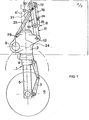
- the landing gear comprises a leg 1 consisting of a box 2, articulated around a lifting axis 3 fixed on the structure of the aerodyne, and in which a damping cylinder 4 can optionally be mounted journalling, this is how the cylinder 4 is crossed by a damper rod 5 carrying, at its lower end, a wheel 6, and constituting with the cylinder 4 a sliding damper such that the rod 5 can protrude at 5 'on the other side of the cylinder 4 relative to the wheel 6, in the compressed position of the shock absorber.
- any rotation of the cylinder 4 vis-à-vis the box 2 is transmitted to the wheel 6 by a compass 7.
- the bracing of the leg 1 in the "gear extended" position is ensured by a counter-plug 8 consisting of a connecting rod 9 , articulated around a fixed axis 10 on the structure of the aerodyne and a lever 11, articulated on the box 2 around an axis 12, and on the connecting rod 9 around an axis 13.
- a jack 25 is articulated by its cylinder around a axis 26 on the box 2, and by its rod, on the connecting rod 9 around an axis 27.
- the axis 27 on the connecting rod 9 being disposed on the same side as that where the strut 8 is located relative to the geometrical axis defined by the fixed axes 3 and 10 in the "gear extended” position as in the "gear retracted” position.
- the axes 26 and 27 are located as close as possible to the two fixed axes 10 and 3, on the aerodyne, so that the actuator is preferably close to the straight line passing through the two fixed axes 3 and 10 of so that if, in any event, point 12 underwent parasitic rotations in force around this axis, the actuator being only very partially affected by these.
- the two axes 26 and 27 are located in the train so that it can operate in the way it will be explained below.
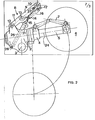
- the axis of rotation 26 it is always located on the same side of the straight line passing through the two axes 3 and 10, for example on the side opposite to the axis 12 when the train is in the extended position (FIG. 1) by relative to this straight line and in the angular sector defined by the two straight lines passing respectively through the axes 3 and 12, on the one hand, and 27 and 12, on the other hand, when the train is in the retracted position (FIG. 2).
- the fixing axis in rotation 27 of the actuator is directly located on the strut 8 and more particularly on the connecting rod 9, but it is obvious that the latter can for example be connected to this strut 8 by any means which can transmit the force to it which is exerted at the end of the jack connected to this axis 27. More specifically, the train operates as follows, when it passes from one of the two retracted and extended positions to the other.
- the jack 25 thus controls the unlocking of the strut 8, then the raising of the undercarriage around the lifting axis 3, the point 12 being lifted by the torque effect around the axis 3 and the force exercised in 26.
- the lifting is carried out against the springs 16 to an intermediate position, in which the axis 13 is aligned with the fixed axes 3 and 10 and between the latter.
- the lifting is carried out with the assistance of the springs 16 and the force of the jack, the strut having ceased to close in the intermediate position, and opening beyond the latter. , to be unfolded again and locked in the aligned position, or slightly beyond the aligned position, under the effect of the springs 16.
- the jack 25 With the assistance of the jack 25, when the undercarriage
- the embodiment illustrated in FIG. 3 aims to improve the train according to FIGS. 1 and 2, and in particular to produce a liftable landing gear without any external positioning stop.
- FIG. 3 essentially represents the main strut of the landing gear with its locking means in a position which may be that of the outgoing gear.
- the part of the train therefore comprises a strut 108 formed by a connecting rod 109 fixed at one of its ends on a rotary axis 110 secured to the chassis of the aircraft and at its other rotary end around an axis 113 on one end a lever 111, the other end of which is rotatably mounted around an axis 112 on a leg 102.
- the lever 111 comprises substantially at the axis 113 an eccentric boss 140 which carries an arm 141, one end of which is rotatably mounted around an axis 142 on this boss, and the other end of which is rotatably mounted on the connecting rod 109 around an axis 143.
- the length of the arm 141 is determined at a certain value, and the three axes 141, 143 and 113 are located substantially at the top of a triangle which can be deformable.
- the arm 141 is formed by two rods 144 and 145 linked substantially by their middle, around a rotary axis 146 so as to be able to pivot one relative to the other, their other ends of these two elements being connected respectively to the axes 143 and 142.
- the rod 144 extends slightly by an extension 160 beyond the axis 143 and carries an axis 146 around which the end of a control jack 125 can pivot, which will make it possible to enter or exit the train by its two positions.
- This cylinder is very schematically constituted by a cylinder 147 in which a piston 148 can move, delimiting two variable-volume chambers 149 and 150 with their supply of pressurized fluid respectively by the lines 151 and 152. It should be noted that this cylinder is shaped so that its length has a value determined so that the two ends 153 and 154 constitute stops for the piston 148, and thus limit its movement.
- the outlet rod 155 of the jack 125 can be connected, depending on the case, directly or indirectly to the leg 102 outlined in the figure.
- the two rods 144 and 145 are subjected to the action of a spring 156 which bears at 157 on an eccentricity 158 of the rod 144 and on the rod 145 at a point 159, so that the two points 157, 159, and the axis 146, are located on a triangle (deformable).
- the improvement according to the invention operates in the following manner.
- the jack exerts a traction on the axis 146 and destroys the quasi alignment 143, 146 and 142 by obtaining in this case of figure a rotation senestrorsum for the rod 144 around the axis and dextrorsum for the other link 145 around the axis 142.
- These movements transmit a traction force on the axis 142 towards the axis 110.
- This also has the consequence of destroying the quasi-alignment of the axes 110, 113 and 112 by obtaining a rotation senestrorsum for the connecting rod 109 and around the axis 110, dextrorsum for the lever 111 around the axis 112.
- This configuration allows positions more stable for the counter-plug 108 and the arm 141, the spring 156 acting in particular on the two links 144 and 145 to confirm and maintain the slight misalignment of the arm formed by the two links 144 and 145.
- the piston 148 of the jack 125 goes towards the bottom 154 of the chamber 150.
- the arm takes the configuration shown and, moreover, the piston being in abutment in the jack, the arm ne.peut not deform more. This stop therefore prevents that when ordering the re-entry of the train there is obtained a break other than that defined above, that is to say senestrorsum and dextrorsum rotations respectively for the rods 144 and 145.
- the distance separating the axes 143 and 142 is maximum, as, moreover, the distances separating the axes 142 and 113 on the one hand, and 143 and 133, on the other hand , are fixed and constant, when the lever 111 has made its dextrorsum rotation relative to the axis 113, it will have arrived at its final position when the distance 143, 142 will be maximum (or almost) preventing any other additional rotation.
- the arm 141 formed of two rods constitutes a means of positioning the lever relative to the rod, giving the same results as a stop, but without its drawbacks.
- the embodiment which has been described here is only one possible mode and in particular by adapting the counter-plug 108 and the arm 141, it is possible to connect the jack 125, on the rod 141 between the axes 143 and 146, or on the rod 145 between the axes 146 and 142 or is beyond the axis 142 relative to the axis 146.
- the rotary attachment point 146 of the jack on a link is not very far from the point of at spot 143 of the arm on the strut (connecting rod 109). This also makes it possible to use only a single jack to obtain all the re-entry and exit operations of the train, as well as locking in particular by the slight misalignment mentioned above. And, moreover, this jack has a very continuous uniform movement to move the train from one position to another.
Landscapes
- Engineering & Computer Science (AREA)
- Mechanical Engineering (AREA)
- Aviation & Aerospace Engineering (AREA)
- Vehicle Cleaning, Maintenance, Repair, Refitting, And Outriggers (AREA)
Applications Claiming Priority (4)
| Application Number | Priority Date | Filing Date | Title |
|---|---|---|---|
| FR7922926A FR2464883B1 (fr) | 1979-09-13 | 1979-09-13 | Train d'atterrissage relevable et orientable pour aerodyne, en particulier pour helicoptere |
| FR7922926 | 1979-09-13 | ||
| FR8014312 | 1980-06-27 | ||
| FR8014312A FR2485471B2 (fr) | 1980-06-27 | 1980-06-27 | Train d'atterrissage relevable et orientable pour aerodyne en particulier pour helicoptere |
Publications (3)
| Publication Number | Publication Date |
|---|---|
| EP0026689A2 true EP0026689A2 (de) | 1981-04-08 |
| EP0026689A3 EP0026689A3 (en) | 1981-04-22 |
| EP0026689B1 EP0026689B1 (de) | 1983-07-06 |
Family
ID=26221347
Family Applications (1)
| Application Number | Title | Priority Date | Filing Date |
|---|---|---|---|
| EP80401281A Expired EP0026689B1 (de) | 1979-09-13 | 1980-09-08 | Anhebbares Hauptfahrwerk für Fahrzeug |
Country Status (4)
| Country | Link |
|---|---|
| US (1) | US4355773A (de) |
| EP (1) | EP0026689B1 (de) |
| CA (1) | CA1139286A (de) |
| DE (1) | DE3064045D1 (de) |
Cited By (2)
| Publication number | Priority date | Publication date | Assignee | Title |
|---|---|---|---|---|
| EP3495263A1 (de) * | 2017-12-11 | 2019-06-12 | Safran Landing Systems | Verfahren zum manövrieren eines luftfahrzeugfahrwerks zwischen einer eingezogenen und einer ausgefahrenen position |
| FR3115013A1 (fr) * | 2020-10-14 | 2022-04-15 | Safran Landing Systems | Atterrisseur d'aéronef équipé d'un dispositif de verrouillage à ressort à lame |
Families Citing this family (6)
| Publication number | Priority date | Publication date | Assignee | Title |
|---|---|---|---|---|
| FR2501153B1 (fr) * | 1981-03-05 | 1986-02-14 | Messier Hispano Sa | Train d'atterrissage de fuselage a roues en tandem |
| FR2503662A1 (fr) * | 1981-04-08 | 1982-10-15 | Messier Hispano Sa | Train d'atterrissage dit a tandem |
| USD335604S (en) | 1989-09-12 | 1993-05-18 | Choon Nang Electrical Appliance Manufactory Limited | Roller blind |
| GB9223714D0 (en) * | 1992-11-12 | 1992-12-23 | British Aerospace | Auxiliary control of aircraft landing gear movement |
| ATE544675T1 (de) * | 2009-11-04 | 2012-02-15 | Agustawestland Spa | Landewerk für ein luftfahrzeug |
| FR2979899B1 (fr) * | 2011-09-09 | 2014-07-18 | Messier Bugatti Dowty | Dispositif d'attelage d'un actionneur de manœuvre d'un atterrisseur d'aeronef |
Family Cites Families (8)
| Publication number | Priority date | Publication date | Assignee | Title |
|---|---|---|---|---|
| US2471603A (en) * | 1944-10-13 | 1949-05-31 | Nat Motor Springs Pty Ltd | Retractable mounting and locking device for the wheels of aircraft |
| GB613430A (en) * | 1944-11-03 | 1948-11-29 | Nat Motor Springs Pty Ltd | A locking and power transmitting mechanism for a member adapted for movement about an axis to and from two fixed positions |
| US2487598A (en) * | 1946-04-26 | 1949-11-08 | Saulnier Raymond | Retractable landing gear |
| US2562778A (en) * | 1946-11-27 | 1951-07-31 | Curtiss Wright Corp | Retractable landing gear |
| US2529401A (en) * | 1947-08-25 | 1950-11-07 | Electro Hydraulics Ltd | Retractable undercarriage for aircraft |
| US2959381A (en) * | 1957-08-28 | 1960-11-08 | Cleveland Pneumatic Ind Inc | Retractable landing gear |
| US3580531A (en) * | 1968-07-19 | 1971-05-25 | Ver Flugtechnische Werke | Retractable main carriage for vertically starting airplanes and airplanes starting on a short runway |
| GB1333200A (en) * | 1971-05-26 | 1973-10-10 | British Aircraft Corp Ltd | Aircraft undercarriages |
-
1980
- 1980-08-08 US US06/176,498 patent/US4355773A/en not_active Expired - Lifetime
- 1980-09-08 DE DE8080401281T patent/DE3064045D1/de not_active Expired
- 1980-09-08 EP EP80401281A patent/EP0026689B1/de not_active Expired
- 1980-09-15 CA CA000360259A patent/CA1139286A/fr not_active Expired
Cited By (8)
| Publication number | Priority date | Publication date | Assignee | Title |
|---|---|---|---|---|
| EP3495263A1 (de) * | 2017-12-11 | 2019-06-12 | Safran Landing Systems | Verfahren zum manövrieren eines luftfahrzeugfahrwerks zwischen einer eingezogenen und einer ausgefahrenen position |
| FR3074777A1 (fr) * | 2017-12-11 | 2019-06-14 | Safran Landing Systems | Procede de manœuvre d'un atterrisseur d'aeronef entre une position deployee et une position retractee |
| CN109895998A (zh) * | 2017-12-11 | 2019-06-18 | 赛峰起落架系统公司 | 在展开位置与缩回位置之间移动飞行器起落架的方法 |
| US11242136B2 (en) | 2017-12-11 | 2022-02-08 | Safran Landing Systems | Method of moving an aircraft undercarriage between a deployed position and a retracted position |
| CN109895998B (zh) * | 2017-12-11 | 2023-06-06 | 赛峰起落架系统公司 | 在展开位置与缩回位置之间移动飞行器起落架的方法 |
| FR3115013A1 (fr) * | 2020-10-14 | 2022-04-15 | Safran Landing Systems | Atterrisseur d'aéronef équipé d'un dispositif de verrouillage à ressort à lame |
| WO2022079187A1 (fr) * | 2020-10-14 | 2022-04-21 | Safran Landing Systems | Atterrisseur d'aeronef equipe d'un dispositif de verrouillage a ressort a lame |
| US12162590B2 (en) | 2020-10-14 | 2024-12-10 | Safran Landing Systems | Aircraft landing gear provided with a leaf spring locking device |
Also Published As
| Publication number | Publication date |
|---|---|
| EP0026689A3 (en) | 1981-04-22 |
| US4355773A (en) | 1982-10-26 |
| CA1139286A (fr) | 1983-01-11 |
| DE3064045D1 (en) | 1983-08-11 |
| EP0026689B1 (de) | 1983-07-06 |
Similar Documents
| Publication | Publication Date | Title |
|---|---|---|
| EP2437978B1 (de) | Verfahren zum betrieb einer fahrwerksanordnung mit einer trennstrebe | |
| CA3031825C (fr) | Atterrisseur a contrefiche a lumiere | |
| CA3026069C (fr) | Procede de manoeuvre d'un atterrisseur d'aeronef entre une position deployee et une position retractee | |
| CA2799688C (fr) | Dispositif de deverrouillage d'un atterrisseur dans une position deployee et atterrisseur equipe d'un tel dispositif | |
| EP3263450B1 (de) | Fahrwerk eines luftfahrzeugs mit drehbarem bedienungsstellglied | |
| CA1226258A (fr) | Atterrisseur de type avant pour aeronef | |
| CA2767857C (fr) | Train avant d'aeronef a dispositif de commande unique pour le relevage et la direction | |
| CA2091235A1 (fr) | Atterrisseur relevable a raccourcissement de jambe | |
| FR2616410A1 (fr) | Dispositif d'atterrissage a poutre basculante | |
| FR2538777A1 (fr) | Atterrisseur pour aeronef | |
| FR2866314A1 (fr) | Trappe de train d'atterrissage a cinematique controlee | |
| FR2998869A1 (fr) | Atterrisseur a contrefiche secondaire a realignement | |
| EP0026689B1 (de) | Anhebbares Hauptfahrwerk für Fahrzeug | |
| EP0385831B1 (de) | Fahrwerk mit schwenkbaren Rädern während des Einziehens | |
| EP0061968B1 (de) | Dreifuss-Fahrgestell | |
| EP0488871B1 (de) | Verriegelungsvorrichtung einer schwenkbaren Radhalterung | |
| CA1225072A (fr) | Atterrisseur de type a balancier | |
| FR2501153A1 (fr) | Train d'atterrissage de fuselage a roues en tandem | |
| EP0062564B1 (de) | Tandem-Fahrgestell | |
| FR2464883A1 (fr) | Train d'atterrissage relevable et orientable pour aerodyne, en particulier pour helicoptere | |
| FR2543105A1 (fr) | Atterrisseur du type avant pour aeronef | |
| CA3048083C (fr) | Mecanisme de verrouillage d'actionneur de roue | |
| FR2546476A1 (fr) | Atterrisseur pour structure d'aeronef | |
| FR2707947A1 (fr) | Train d'atterrissage d'aéronef, du type à relevage latéral. | |
| FR2485471A2 (fr) | Train d'atterrissage relevable et orientable pour aerodyne en particulier pour helicoptere |
Legal Events
| Date | Code | Title | Description |
|---|---|---|---|
| PUAI | Public reference made under article 153(3) epc to a published international application that has entered the european phase |
Free format text: ORIGINAL CODE: 0009012 |
|
| PUAL | Search report despatched |
Free format text: ORIGINAL CODE: 0009013 |
|
| AK | Designated contracting states |
Designated state(s): DE GB IT |
|
| AK | Designated contracting states |
Designated state(s): DE GB IT |
|
| 17P | Request for examination filed |
Effective date: 19810529 |
|
| ITF | It: translation for a ep patent filed | ||
| GRAA | (expected) grant |
Free format text: ORIGINAL CODE: 0009210 |
|
| AK | Designated contracting states |
Designated state(s): DE GB IT |
|
| REF | Corresponds to: |
Ref document number: 3064045 Country of ref document: DE Date of ref document: 19830811 |
|
| PLBE | No opposition filed within time limit |
Free format text: ORIGINAL CODE: 0009261 |
|
| STAA | Information on the status of an ep patent application or granted ep patent |
Free format text: STATUS: NO OPPOSITION FILED WITHIN TIME LIMIT |
|
| 26N | No opposition filed | ||
| PGFP | Annual fee paid to national office [announced via postgrant information from national office to epo] |
Ref country code: DE Payment date: 19840919 Year of fee payment: 5 |
|
| PG25 | Lapsed in a contracting state [announced via postgrant information from national office to epo] |
Ref country code: DE Effective date: 19890601 |
|
| PGFP | Annual fee paid to national office [announced via postgrant information from national office to epo] |
Ref country code: GB Payment date: 19920907 Year of fee payment: 13 |
|
| PG25 | Lapsed in a contracting state [announced via postgrant information from national office to epo] |
Ref country code: GB Effective date: 19930908 |
|
| GBPC | Gb: european patent ceased through non-payment of renewal fee |
Effective date: 19930908 |