EP0027064A1 - Verfahren und Apparat zum Stützen und Festhalten insbesondere von Geflügel - Google Patents
Verfahren und Apparat zum Stützen und Festhalten insbesondere von Geflügel Download PDFInfo
- Publication number
- EP0027064A1 EP0027064A1 EP80401277A EP80401277A EP0027064A1 EP 0027064 A1 EP0027064 A1 EP 0027064A1 EP 80401277 A EP80401277 A EP 80401277A EP 80401277 A EP80401277 A EP 80401277A EP 0027064 A1 EP0027064 A1 EP 0027064A1
- Authority
- EP
- European Patent Office
- Prior art keywords
- debeaking
- volatile
- assembly
- support
- station
- Prior art date
- Legal status (The legal status is an assumption and is not a legal conclusion. Google has not performed a legal analysis and makes no representation as to the accuracy of the status listed.)
- Granted
Links
- 238000000034 method Methods 0.000 title claims abstract description 19
- 244000144977 poultry Species 0.000 title 1
- 210000003323 beak Anatomy 0.000 claims description 19
- 230000003213 activating effect Effects 0.000 claims description 13
- 239000003039 volatile agent Substances 0.000 claims description 11
- 239000007789 gas Substances 0.000 claims description 10
- 239000000725 suspension Substances 0.000 claims description 8
- 238000010438 heat treatment Methods 0.000 claims description 6
- 238000001816 cooling Methods 0.000 claims description 4
- 238000013021 overheating Methods 0.000 claims description 4
- 238000011144 upstream manufacturing Methods 0.000 claims description 4
- 238000002485 combustion reaction Methods 0.000 claims description 3
- 238000006073 displacement reaction Methods 0.000 claims description 3
- 238000003780 insertion Methods 0.000 claims description 3
- 230000037431 insertion Effects 0.000 claims description 3
- UGFAIRIUMAVXCW-UHFFFAOYSA-N Carbon monoxide Chemical compound [O+]#[C-] UGFAIRIUMAVXCW-UHFFFAOYSA-N 0.000 claims 1
- 239000012190 activator Substances 0.000 claims 1
- 238000007664 blowing Methods 0.000 claims 1
- 239000003546 flue gas Substances 0.000 claims 1
- 230000000452 restraining effect Effects 0.000 abstract 1
- 241000271566 Aves Species 0.000 description 11
- 239000000567 combustion gas Substances 0.000 description 3
- 230000007246 mechanism Effects 0.000 description 3
- 230000008569 process Effects 0.000 description 3
- ATUOYWHBWRKTHZ-UHFFFAOYSA-N Propane Chemical compound CCC ATUOYWHBWRKTHZ-UHFFFAOYSA-N 0.000 description 2
- 238000013459 approach Methods 0.000 description 2
- 238000012986 modification Methods 0.000 description 2
- 230000004048 modification Effects 0.000 description 2
- 239000003607 modifier Substances 0.000 description 2
- 241000293849 Cordylanthus Species 0.000 description 1
- 241000288147 Meleagris gallopavo Species 0.000 description 1
- 241001465754 Metazoa Species 0.000 description 1
- 241000272458 Numididae Species 0.000 description 1
- 241000287107 Passer Species 0.000 description 1
- 240000008042 Zea mays Species 0.000 description 1
- WYTGDNHDOZPMIW-RCBQFDQVSA-N alstonine Natural products C1=CC2=C3C=CC=CC3=NC2=C2N1C[C@H]1[C@H](C)OC=C(C(=O)OC)[C@H]1C2 WYTGDNHDOZPMIW-RCBQFDQVSA-N 0.000 description 1
- 238000005452 bending Methods 0.000 description 1
- 230000005540 biological transmission Effects 0.000 description 1
- 239000001273 butane Substances 0.000 description 1
- 230000008859 change Effects 0.000 description 1
- 108010038764 cytoplasmic linker protein 170 Proteins 0.000 description 1
- 230000000694 effects Effects 0.000 description 1
- 239000002184 metal Substances 0.000 description 1
- IJDNQMDRQITEOD-UHFFFAOYSA-N n-butane Chemical compound CCCC IJDNQMDRQITEOD-UHFFFAOYSA-N 0.000 description 1
- OFBQJSOFQDEBGM-UHFFFAOYSA-N n-pentane Natural products CCCCC OFBQJSOFQDEBGM-UHFFFAOYSA-N 0.000 description 1
- 230000000149 penetrating effect Effects 0.000 description 1
- 238000003825 pressing Methods 0.000 description 1
- 238000012545 processing Methods 0.000 description 1
- 239000001294 propane Substances 0.000 description 1
- 230000000284 resting effect Effects 0.000 description 1
- 239000000779 smoke Substances 0.000 description 1
- 238000006467 substitution reaction Methods 0.000 description 1
Images


Classifications
-
- A—HUMAN NECESSITIES
- A61—MEDICAL OR VETERINARY SCIENCE; HYGIENE
- A61D—VETERINARY INSTRUMENTS, IMPLEMENTS, TOOLS, OR METHODS
- A61D1/00—Surgical instruments for veterinary use
- A61D1/005—Devices for trimming, cutting, cauterising beaks, spurs, or the like, of poultry or other birds
Definitions
- the present invention essentially relates to a method and an apparatus for automatic support and containment, in particular of birds, preferably young chicks, turkey poults, guinea fowls, said methods and apparatus being in a preferred embodiment applied to debeaking said birds.
- an improved method and apparatus for automatic support and containment, in particular of volatiles said method and apparatus preferably being applied to automatic debeaking of volatiles.
- this method is also characterized in that it comprises lowering the debeaking assembly from its non-operating position disposed above the table at the same time as the debeaking assembly is rotated to follow the rotation of the table; and the horizontal rotation relative to the debeaking assembly of the debeaking element towards the support vis-à-vis so as to debeak the volatile vis-à-vis.
- the upper and lower spouts of the volatile are debeaked.
- this method is characterized in that it comprises the lowering of the debeaking assembly from its non-operative position disposed above of the table at the same time as the debeaking assembly is rotated to follow the rotation of the table; and only the vertical lowering with the debeaking assembly of the debeaking element so as to debeak only the upper beak of the bird.
- the apparatus according to the present invention is characterized in that it further comprises a debeaking assembly in the vicinity of said table downstream relative to the loading station but upstream relative to the station unloading, said debeaking assembly comprising a debeaking element, movable between an operating position and a non-operating position so that each support is capable of passing, by rotation of the table, into the station formed by the debeaking assembly , and activating means for moving said debeaking assembly, with its debeaking element, to its operating position upon arrival of a support at the station formed for the debeaking assembly and after returning the debeaking assembly with its debeaking element to its non-operating position.
- a debeaking assembly in the vicinity of said table downstream relative to the loading station but upstream relative to the station unloading, said debeaking assembly comprising a debeaking element, movable between an operating position and a non-operating position so that each support is capable of passing, by rotation of the table, into the station formed by the
- said means for suspending the bird carrier comprises a front piece constituting at least one part of a helmet, fixed to said table and having a recess receiving at least one part the head of the bird, said front piece having an opening at the top of the recess through which the beak protrudes while being kept closed.
- Said suspension means further comprises a pair of profiled retaining devices mounted on said table to hold the head of the bird in said recess.
- said retaining devices are arranged to extend across opposite edges of the bird's neck and then along the head to hold the head in the recess which is preferably conical.
- the release means comprise a release element for automatically causing said release means to release its volatile on its arrival at the unloading station.
- said releasing means comprise a spring pushing said retaining devices into a closed position against a volatile
- said releasing means include a cam to force said retaining devices to separate towards an open position to release said volatile.
- each support further comprises a control element disposed in the passage of a volatile which is loaded into said support, for activating said cam by means of a connection so as to allow said spring to close said retaining devices on a volatile when the volatile is pressed against the control element.
- said release element is arranged in the passage of said connection to return said cam to its position keeping the separate retaining devices in the open position.
- the control element also serves as a tongue depressor, acting either against the neck or between the spouts.
- the debeaking assembly preferably comprises means for heating the debeaking element to burn the end of the spout and the aforementioned activating means advantageously comprise means for keeping the debeaking element heated against the end of the spout with enough pressure to burn the beak without damaging it so as to avoid injuring the beak, thus allowing the bird to feed.
- the shape of the debeaking element and its movement are chosen to operate either one, that is to say the lower spout or the upper spout, or the two spouts and to provide the desired shape and the degree of debeaking .
- the means for heating the debeaking element preferably comprises a gas nozzle and a source of flammable gas and, advantageously a means for supplying an air current in a tube arranged opposite the gas nozzle for remove both the hot air (to avoid overheating of any part that touches the bird) and the odor and smoke around the debeaker, said air stream being blown into said tube a place sufficiently spaced from the debeaking element so as to avoid cooling the debeaking element.
- this current of air makes it possible to significantly reduce the flow envelope of the combustion gases brought to a very high temperature and which would be liable to seriously burn parts of the volatile and in particular the nozzle, that the we don't want to heat or burn.
- the invention thus provides a suitable debeaking controlled at very high speed, requiring only a single operator who quickly and easily loads birds such as young chicks. Since the beak is simply burned and is not mechanically damaged by application of the debeaking element, the beak can be used by the bird for food.
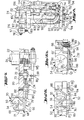
- the apparatus comprises a frame 1 mounted movable vis-à-vis a support leg 2 resting on the ground.
- the apparatus comprises a table 20 rotatably mounted on the chassis 1, supported by a mandrel 22 forming the drive shaft of the rotary table 20, said shaft 22 being brought into rotation about the axis 24 by the motor 26 by a system drive 27 comprising a variable speed drive transmission 28.
- the turntable 20 comprises eight notches 21 to which are mounted volatile supports 30 for receiving volatiles at the loading station 31.
- Each volatile support 30 comprises means 32 for suspending a volatile by its head with the head held immobilized.
- the apparatus further comprises according to the preferred embodiment a debeaking assembly 34 at the debeaking station 35 in the vicinity of the rotary table 20, movable between an operating position and a non-operating position so that each support 30 is capable to pass, by rotation of the table 20, into the station 35 formed by the debeaking assembly 34. It also includes an unloading station 40 (see FIGS. 2,4 and 5).
- the apparatus comprises, according to the preferred embodiment, also activating means 41 for moving the debeaking assembly 34, comprising a debeaking element 110, to its operating position when a support 30 arrives at the station 35 formed by the debeaking assembly 34 and after to return the debeaking assembly 34 to its non-operating position (shown in Figure 1).
- the suspension means 32 of each support 30 comprise a front piece 50 constituting at least one part of the helmet, fixed to said table 20, and consisting of a metal block with a recess 54 to receive at least part of the head of the bird.
- the front piece 50 also has an opening 56 at the top of the recess 54 just wide enough to admit the end of the beak of the bird.
- the recess 54 is preferably conical and is shaped to comfortably receive the head of the volatile to be treated.
- the front piece 50 is removable and replaceable to allow the substitution of various shapes.
- Each of the supports 30 further comprises a control element 62 constituted for example by a rod, arranged in the passage of a volatile which is loaded in said support 30 and for this purpose it extends horizontally through the recess 54, and is folded to extend into the recess.
- a control element 62 constituted for example by a rod, arranged in the passage of a volatile which is loaded in said support 30 and for this purpose it extends horizontally through the recess 54, and is folded to extend into the recess.
- Another configuration for the control element 62 is to extend straight through the notch 21 below the front piece 50, as shown at 62 ′ in FIG. 6a, in which case said control element acts against the neck of the bird rather than between its beaks.
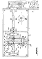
- the suspension means 32 of each support 30 advantageously also comprise a pair of retaining devices 66 mounted on said table 20 for holding the head of a bird in said recess 54
- the retaining devices 66 are in the embodiment shown constituted by the free ends of a spring 70 serpentine ( Figures 3 to 5), and are formed to extend across opposite edges of the bird's neck and then up along and against the back of the head.
- the first parts that extend across the neck are curved to conform to the neck and approach each other at 68, where the retainers are folded up to form vertical parts 69 s' bending at their free end to conform to the head of the bird.
- the spring 70 is wound around the disc 71, which is mounted on the bottom wall of the table 20 on the upright 72 which extends across the slot 73 of the disc to allow a radial adjustment (from the axis 24) for varying the span of the retaining devices 66.
- the retaining devices 66 pass between the discs 76 and 78 of the element 74, on the opposite edges of an eccentric cam 80 in the form of a bar fixed between the disks.
- the discs 76 and 78 and the cam 80 are mounted to pivot around the axis 81 on a shaft 82 which is fixed in the table 20 to open and close the retaining devices 66.
- arms 84 and 85 fixed to the element 74 extend in a general opposite direction from the shaft 81, and the arm 86 extends from the upright 88 to constitute a stopper vis-à-vis the arm 84 ( figure 4), preventing a rotation to the right of the cam 80 (from the point of view of figure 4, looking from the side below the table 20), which thus maintains the availability retaining sitive 66 open against the force of the spring 70.
- the upright 88 is mounted on the table 20 to pivot around the axis 89, and comprises fixed thereon above the table one end of the rod 62.
- a spring 90 pushes the upright 88 back into this position.
- An inward movement of the control element 62 causes the upright 88 to pivot, moving the arm 86 away from the arm 84 to release the latter and allow the spring 70 to close the retainers 66, by rotating the cam 80 until it is aligned and balanced between the retainers 66 ( Figure 4).
- a hollow upright 94 is mounted on the table 20 with its opening 96 positioned to be locked by the arm 84, which enters the slot 97 of the upright when the retainers are open.
- the upright 94 thus also acts as a stopper vis-à-vis the arm 84 to protect the elastic limit of the retaining device 66, and also acts as a stopper vis-à-vis the arm 86 in its locking position ( Figure 7).
- a release element constituted for example by a cam 98, is mounted on the drive shaft 22 at the unloading station 40 and is advantageously arranged in the passage of the end 99 turned down the arm 85, so as to pivot the arm 85, and from there the cam 60, to the left, that is to say clockwise (seen as above, from below table) to the open position, for which the spring 90 causes the arm 86 to pivot in turn to set up against the arm 84, by locking the mechanism in the open position.
- the aforementioned structure constitutes a connection which, with the release element 98 together form the release or release means mentioned above to cause the support 30 to release its volatile when it arrives at the unloading station 40 .
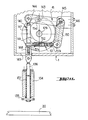
- the debeaking assembly 34 ( Figure 8) includes a debeaking member 110 with an open end formed to fit around the end of the bird's beak. Although the end 111 is shown in FIG. 8 with a circular section, it can have other forms, depending on whether one wishes to treat one spout or both spouts, and according to the degree and the form of debeaking desired.
- This shape can be the conical shape represented in FIG. 16 which is particularly suitable for carrying out the debeaking of the two spouts simultaneously or the semi-conical shape represented in FIG. 17 which is specifically adapted for performing the debeaking of the upper spout (in position shown) or the lower spout (in the reverse position).
- the debeaking assembly 34 also includes means 112 for heating the debeaking element 110 to burn the spout.
- the heating means 112 comprises a nozzle 114 connected by the tube 116 to a source of propane or another gas to supply a flame to the debeaking element 110, typically above 700 ° C.
- the debeaking assembly 34 further comprises means 113 for removing the hot air around the nozzle 114 to protect the appliance from overheating and for removing the combustion products from debeaking.
- said means 113 for removing hot air comprises a duct outlet 118, opposite the nozzle 114 which is supplied with a stream of fresh air through the conduit 115 connected to a larger tube 117.
- a fan means 119 blows air into the tube 117.
- the debeaking element 110 extends between the nozzle 114 and the outlet duct 118 and is rigidly fixed to the tube 117. It should be noted that the free end of the conduit 115 is disposed in a location sufficiently spaced from the debeaking element 110 so as to avoid cooling the debeaking element 110 and especially the end 111 which performs debeaking.
- the drive system 27 driven by the motor 26 and acting on the drive axis 22 comprises, as can be seen from FIG. 10, a main shaft 120 having at one end a toothed wheel 121 cooperating with a screw end 122 on an axis 123 of a pulley 124 supporting a belt 125 activated by a pulley 126 fixed on the arm 127 of the motor 26.
- the other end of the main shaft 120 is connected by an oldham seal 128 to a secondary shaft 129 comprising an endless screw 130 cooperating with a toothed wheel 131 fixed to the shaft 22 for driving the rotary table 20.
- the main and secondary shafts 120, 129 are rotatably mounted using several bearings 132, relative to the chassis 1.
- the debeaking assembly 34 is mounted on a mobile support 134, the latter being guided near one end 134a by the drive axis 22 to rotate freely relative to the drive axis 22.
- the mobile support 134 carries at its lower end on a plate 135 (see FIG. 11) which is fixed to an operating shaft 136 of the mobile support 134 through an orifice 137 passing through it at a location arranged preferably opposite the end 134a of the movable support 134, said operating shaft 136 being connected to the activating means 41 described below.
- the activating means 41 comprise a wheel 140 rigidly mounted on the secondary shaft 129, constituting a double cam, each face comprising a cam path such as the cam path 141 shown in FIGS. 1, 11 and 10, the other path of cam 142 being shown only in FIG. 10.
- the cam track 141 carries a roller 143 fixed to a lever 144 which is articulated at one end on an axis 145 rotatably mounted on a bearing 146, the other end supporting a vertical connecting rod 147 , hinged mounted on the lever 144, the other end of the vertical connecting rod 147 being connected to the operating shaft 136 by a yoke 148 passing through a door 149 produced in the chassis 1.
- a control connecting rod 150 is fixed to one end of the axis 145, and at its other free end supports a drive rod 151 articulated at one end on the control rod 150 and is articulated at its other free end to the vertical rod 147. It can thus be seen that lever 1 44, the control rod 150, the drive rod 151 and the vertical rod 147 substantially form an articulated parallelogram. It should be noted that preferably the drive link 151 is made in two parts 151a and 151b which are threaded and connected using a sleeve 152 also threaded so as to vary the length of the drive link 151 as well as the rotation of the mobile support 134.
- the debeaking assembly 34 comprises three parts 160, 161, 162.
- the part 160 comprises, as shown in FIG. 13, two guide elements 163, 164 passing through orifices 165; 166, respectively, made through the movable support 134.
- the guide element 163 is long enough to abut at its free end against the rotary table 20 when the movable support 134 is lowered, its free end being provided with a screw 167 to vary its total length.
- the part 161 comprises a finger 168 provided with a screw 169 securing the part 162 to the part 161.
- the part 162 comprises a spring clip 170 for attaching a spring 171 between the part 162 and the clip 172 fixed to the movable support 134 Openings 173, 174, 175 are made respectively at parts 160, 161 and 162 to allow passage to the air tube 117 and to the gas pipe 116. However, the gas pipe 116 and the air pipe 117 are fixed to the part 162 by a pinching means 176.
- the part 161 can be secured to the part 160 using a screw 177 capable of penetrating a hole provided in the part 160.
- the part 161 comprises at its lower side an additional screw 178 (shown in FIG. 13) bearing on the mobi support 134 when the screw 167 does not already abut against the turntable 20.
- the finger 168 protrudes beyond in a recess 180 produced in the part 160, the dimension of the recess 180 being predetermined to allow the parts 162 and 161 to be pivoted within determined limits when the screw 177 does not engage in the part 160.
- the air tube 117 pivots with the part 162 and that the debeaking element is fixed to the air tube 177, this will allow the debeaking element to pivot to perform debeaking.
- the parts 162 and 161 are fixed to the part 160 and do not pivot. In this case the debeaking element 110 is lowered only vertically to debeak the upper spout.
- FIG. 15 we show in more detail the mechanism for lowering or lifting the frame 1 relative to the support leg 2.
- This mechanism comprises a crank 181 comprising a worm 182 so as to raise or lower the frame 1 relative to the support leg 2.
- the chassis 1 advantageously comprises a locking means 183 shown in FIG. 1 for locking the chassis 1 in a determined position.
- the birds can be counted using any counting device known per se and which has therefore not been shown.
- activating means 41 are such that the debeaking assembly 34 is moved through its complete cycles the same number of times as the number of supports 30 provided on the table 20 for each complete rotation of the table 20.
- an operator loads a bird, such as a chick, into each support 30 when it reaches the station 31 by exerting pressure on the back of the bird's head to separate its upper and lower spouts, and pressing the open spout against the control element 62 to close the retaining devices 66, as described above, and forcing (using the conical surface of the recess 54) the spout to close and introduce itself in the opening 56 of the front piece 50.
- a bird such as a chick
- the mobile support 134 is brought by the activating means 41 previously described to descend to the table 20 and thus bring the debeaking assembly 34 also to descend and pivot outwards towards the support 30.
- the guide element 136 abuts against the table 20, the downward movement of the part 160 of the debeaking assembly ceases.
- the flow of positive air from the duct 115 into the exhaust duct 118 induces a current of air of the front piece 50, in the tube 118, by removing the excess of hot air to avoid overheating of the volatile or of the parts which it touches, by cooling the front piece 50, and also by removing the combustion products when the beak is burnt.
- the screw 117 is engaged in the part 160 to secure the parts 162 and 161 with the part 160.
- a downward movement of the part 160 caused by a movement towards the bottom of the movable support 134 will only make a vertical downward movement of the debeaking element 110 on the upper spout to be debeaked by burning according to the present invention.
- the movable support 134 When debeaking is finished, after a determined period of time provided by the cam tracks of the wheel 140 of the activating means 41, the movable support 134 begins to rise and begins to rotate the parts 161 and 162 by acting on the screw 178 when the screw 177 is not engaged with the part 160 so that the debeaking element 110 is withdrawn horizontally from the volatile, and the continuation of the upward movement of the movable support 134 also brings about an upward movement of the debeaking assembly, the latter moving rapidly upwards to its starting position.
- the operation is simple and safe, and allows extremely controlled processing at an extremely high speed, for example, as fast as 6000 birds, such as chicks, per hour.
- the nature of the gas used to feed the nozzle 114 can be arbitrary. It is generally preferred to use butane but one could very well use any other combustion gas produced industrially, taking the precaution of placing a nozzle adapted to the nature of the combustion gas used.
- the spring 90 of the upright 88 can be replaced by a cam system similar to that of the cam 98 at the unloading station 40, which makes the device more reliable by avoiding the use of a spring which is likely to partially lose its initial qualities after a certain number of hours of operation.
- the present invention is in no way limited to the embodiment described and shown, which has been given only by way of example.
- the invention includes all the means constituting technical equivalents of the means described as well as their combinations if that., - these are carried out according to the spirit and implemented in the context of the claims which follow.
- the invention also applies to the support and restraint of animals in addition to the birds mentioned above as a preferred embodiment.
Landscapes
- Health & Medical Sciences (AREA)
- Life Sciences & Earth Sciences (AREA)
- Veterinary Medicine (AREA)
- Zoology (AREA)
- Surgery (AREA)
- Engineering & Computer Science (AREA)
- Birds (AREA)
- Wood Science & Technology (AREA)
- Animal Husbandry (AREA)
- Animal Behavior & Ethology (AREA)
- General Health & Medical Sciences (AREA)
- Public Health (AREA)
- Catching Or Destruction (AREA)
- Processing Of Meat And Fish (AREA)
- Feeding And Watering For Cattle Raising And Animal Husbandry (AREA)
- Supplying Of Containers To The Packaging Station (AREA)
Priority Applications (1)
| Application Number | Priority Date | Filing Date | Title |
|---|---|---|---|
| AT80401277T ATE13010T1 (de) | 1979-09-14 | 1980-09-05 | Verfahren und apparat zum stuetzen und festhalten insbesondere von gefluegel. |
Applications Claiming Priority (2)
| Application Number | Priority Date | Filing Date | Title |
|---|---|---|---|
| FR7923018A FR2464700A1 (fr) | 1979-09-14 | 1979-09-14 | Procede et appareil de debecquage automatique de volatiles, de preference de jeunes poussins, dindonneaux, pintadeaux |
| FR7923018 | 1979-09-14 |
Publications (2)
| Publication Number | Publication Date |
|---|---|
| EP0027064A1 true EP0027064A1 (de) | 1981-04-15 |
| EP0027064B1 EP0027064B1 (de) | 1985-05-02 |
Family
ID=9229670
Family Applications (1)
| Application Number | Title | Priority Date | Filing Date |
|---|---|---|---|
| EP80401277A Expired EP0027064B1 (de) | 1979-09-14 | 1980-09-05 | Verfahren und Apparat zum Stützen und Festhalten insbesondere von Geflügel |
Country Status (10)
| Country | Link |
|---|---|
| US (2) | US4375814A (de) |
| EP (1) | EP0027064B1 (de) |
| JP (1) | JPS5696639A (de) |
| AT (1) | ATE13010T1 (de) |
| BR (1) | BR8005765A (de) |
| CA (1) | CA1160112A (de) |
| DE (1) | DE3070582D1 (de) |
| ES (1) | ES8105565A1 (de) |
| FR (1) | FR2464700A1 (de) |
| MX (1) | MX7111E (de) |
Cited By (4)
| Publication number | Priority date | Publication date | Assignee | Title |
|---|---|---|---|---|
| EP0148692A3 (de) * | 1983-12-30 | 1986-06-11 | Albert Joseph Albin Gourlandt | Vorrichtung zur Behandlung von Tieren, insbesondere von Federvieh |
| FR2614175A1 (fr) * | 1987-04-23 | 1988-10-28 | Gourlandt Albert | Perfectionnements a un procede et un appareil de debecquage automatique de volatiles, tels que de jeunes poussins, dindonneaux, pintadeaux, canards. |
| FR2808671A1 (fr) | 2000-05-15 | 2001-11-16 | Albert Gourlandt | Dispositif de vaccination au niveau du bec de volatiles nouveau-nes ou jeunes |
| CN1076269C (zh) * | 1996-09-26 | 2001-12-19 | 阿尔法康公司 | 用双轴拉伸制造塑料管的方法 |
Families Citing this family (16)
| Publication number | Priority date | Publication date | Assignee | Title |
|---|---|---|---|---|
| JPH01278065A (ja) * | 1988-04-28 | 1989-11-08 | Hitachi Ltd | 半導体記憶装置 |
| US5651731A (en) * | 1995-06-23 | 1997-07-29 | Nova-Tech Engineering, Inc. | Method and apparatus for debeaking poultry |
| US6059804A (en) * | 1999-03-12 | 2000-05-09 | Baer; Amos | Portable debeaking system |
| IT1311478B1 (it) * | 1999-07-07 | 2002-03-13 | Poultry Vacc Sas Di Zermoglio | Apparecchiatura automatica per la vaccinazione di pulcini e similivolatili. |
| US6609479B2 (en) * | 2001-01-05 | 2003-08-26 | Merial Limited | Bird vaccinating device and method of operation |
| EP1549235A4 (de) * | 2002-09-17 | 2010-05-05 | Extraortho Inc | EINSEITIGES FIXIERGERûT |
| CA2505744C (en) * | 2002-11-14 | 2012-05-29 | Visionmed, Llc | Method for using a fixator device |
| US7232450B2 (en) * | 2003-01-17 | 2007-06-19 | Nova-Tech Engineering, Inc. | Apparatus and method for upper and lower beak treatment |
| US7363881B2 (en) * | 2003-11-06 | 2008-04-29 | Nova-Tech Engineering, Inc. | Beak treatment with tongue protection |
| KR101236913B1 (ko) | 2003-11-06 | 2013-02-25 | 노바-테크 엔지니어링, 인코포레이티드 | 자동화된 가금류 가공 방법 및 장치 |
| US8499721B2 (en) * | 2003-11-06 | 2013-08-06 | Nova-Tech Engineering, Inc. | Apparatus and method for nasal delivery of compositions to birds |
| US7004112B2 (en) | 2003-11-06 | 2006-02-28 | Nova-Tech Engineering, Inc. | Automated hatchling processing method and system |
| US7802541B2 (en) * | 2006-10-17 | 2010-09-28 | Jesse Jones | Poultry vaccination apparatus and method |
| ES2567642B2 (es) * | 2014-10-22 | 2016-10-17 | Fabricaciones Mecánicas Guadaíra, S.L. | Aparato para despicar e inyectar polluelos de aves de corral |
| WO2021205312A1 (en) * | 2020-04-06 | 2021-10-14 | Target Point Technologies Ltd. | Combination injector and spray device |
| CN217657693U (zh) * | 2021-10-29 | 2022-10-28 | 诺瓦-科技工程有限责任公司 | 家禽喙处理系统 |
Citations (7)
| Publication number | Priority date | Publication date | Assignee | Title |
|---|---|---|---|---|
| US3136315A (en) * | 1962-03-01 | 1964-06-09 | Lyon James | Portable hand operated beak cutter and cauterizer for fowl and the like |
| US3274974A (en) * | 1965-03-04 | 1966-09-27 | Reynolds Lamar | Baby chick debeaking and packing mechanism |
| US3774578A (en) * | 1972-12-15 | 1973-11-27 | A Randolph | Poultry handling apparatus |
| FR2281060A1 (fr) * | 1974-08-07 | 1976-03-05 | Lissot Jean | Appareil automatique pour faconner le bec de jeunes volailles et effectuer la vaccination buccale |
| DE2620258A1 (de) * | 1975-08-11 | 1977-02-24 | Ray Goodwin | Anlage zum behandeln von kueken |
| DE2722811A1 (de) * | 1977-05-20 | 1978-11-23 | Auburn Res Found | Schnabelkuerzungsvorrichtung fuer gefluegel |
| US4191130A (en) * | 1978-08-14 | 1980-03-04 | Musgrave Harry J | Chick processing apparatus |
Family Cites Families (4)
| Publication number | Priority date | Publication date | Assignee | Title |
|---|---|---|---|---|
| US2448421A (en) * | 1945-07-12 | 1948-08-31 | Swift & Co | Poultry shackle |
| US2731016A (en) * | 1954-06-11 | 1956-01-17 | Roy R Miller | Poultry beak cutting device |
| US2952031A (en) * | 1958-02-14 | 1960-09-13 | Emma B Breitkreutz | Fowl restraining devices |
| US3302645A (en) * | 1963-11-22 | 1967-02-07 | Jesse W Lockmiller | Chicken vaccination and debeaking apparatus |
-
1979
- 1979-09-14 FR FR7923018A patent/FR2464700A1/fr active Granted
-
1980
- 1980-09-04 CA CA000359735A patent/CA1160112A/en not_active Expired
- 1980-09-05 AT AT80401277T patent/ATE13010T1/de not_active IP Right Cessation
- 1980-09-05 DE DE8080401277T patent/DE3070582D1/de not_active Expired
- 1980-09-05 EP EP80401277A patent/EP0027064B1/de not_active Expired
- 1980-09-08 US US06/184,970 patent/US4375814A/en not_active Expired - Lifetime
- 1980-09-10 BR BR8005765A patent/BR8005765A/pt not_active IP Right Cessation
- 1980-09-12 MX MX809026U patent/MX7111E/es unknown
- 1980-09-12 ES ES495025A patent/ES8105565A1/es not_active Expired
- 1980-09-16 JP JP12732780A patent/JPS5696639A/ja active Granted
-
1982
- 1982-09-30 US US06/430,604 patent/US4446819A/en not_active Expired - Lifetime
Patent Citations (7)
| Publication number | Priority date | Publication date | Assignee | Title |
|---|---|---|---|---|
| US3136315A (en) * | 1962-03-01 | 1964-06-09 | Lyon James | Portable hand operated beak cutter and cauterizer for fowl and the like |
| US3274974A (en) * | 1965-03-04 | 1966-09-27 | Reynolds Lamar | Baby chick debeaking and packing mechanism |
| US3774578A (en) * | 1972-12-15 | 1973-11-27 | A Randolph | Poultry handling apparatus |
| FR2281060A1 (fr) * | 1974-08-07 | 1976-03-05 | Lissot Jean | Appareil automatique pour faconner le bec de jeunes volailles et effectuer la vaccination buccale |
| DE2620258A1 (de) * | 1975-08-11 | 1977-02-24 | Ray Goodwin | Anlage zum behandeln von kueken |
| DE2722811A1 (de) * | 1977-05-20 | 1978-11-23 | Auburn Res Found | Schnabelkuerzungsvorrichtung fuer gefluegel |
| US4191130A (en) * | 1978-08-14 | 1980-03-04 | Musgrave Harry J | Chick processing apparatus |
Cited By (5)
| Publication number | Priority date | Publication date | Assignee | Title |
|---|---|---|---|---|
| EP0148692A3 (de) * | 1983-12-30 | 1986-06-11 | Albert Joseph Albin Gourlandt | Vorrichtung zur Behandlung von Tieren, insbesondere von Federvieh |
| FR2614175A1 (fr) * | 1987-04-23 | 1988-10-28 | Gourlandt Albert | Perfectionnements a un procede et un appareil de debecquage automatique de volatiles, tels que de jeunes poussins, dindonneaux, pintadeaux, canards. |
| EP0291371A1 (de) * | 1987-04-23 | 1988-11-17 | Poultry Robotic Systems Limited | Vorrichtung und Verfahren zum automatischen Entschnabeln von Geflügel |
| CN1076269C (zh) * | 1996-09-26 | 2001-12-19 | 阿尔法康公司 | 用双轴拉伸制造塑料管的方法 |
| FR2808671A1 (fr) | 2000-05-15 | 2001-11-16 | Albert Gourlandt | Dispositif de vaccination au niveau du bec de volatiles nouveau-nes ou jeunes |
Also Published As
| Publication number | Publication date |
|---|---|
| ES495025A0 (es) | 1981-06-16 |
| ES8105565A1 (es) | 1981-06-16 |
| EP0027064B1 (de) | 1985-05-02 |
| JPH0113811B2 (de) | 1989-03-08 |
| US4446819A (en) | 1984-05-08 |
| MX7111E (es) | 1987-06-29 |
| FR2464700B1 (de) | 1985-03-22 |
| DE3070582D1 (en) | 1985-06-05 |
| CA1160112A (en) | 1984-01-10 |
| US4375814A (en) | 1983-03-08 |
| BR8005765A (pt) | 1981-03-24 |
| JPS5696639A (en) | 1981-08-04 |
| FR2464700A1 (fr) | 1981-03-20 |
| ATE13010T1 (de) | 1985-05-15 |
Similar Documents
| Publication | Publication Date | Title |
|---|---|---|
| EP0027064B1 (de) | Verfahren und Apparat zum Stützen und Festhalten insbesondere von Geflügel | |
| EP0477352A1 (de) | Greifklemme und damit ausgerüstete behandlungsmaschine für gegenstände, insbesondere flaschen. | |
| EP0123655A2 (de) | Automatischer Apparat zum Verpacken von Obst- und Gemüsebehältern mittels einer Netzumwicklung versehen mit Stützbändern und Etiketten | |
| WO2006084990A1 (fr) | Dispositif rotatif de transfert de recipients | |
| CA2228718C (fr) | Dispositif de moulage de recipients en materiau thermoplastique et installation de fabrication de recipients en faisant applications | |
| EP0000851B1 (de) | Automatische Vorrichtung zum Zerteilen eines thermoplastischen Schlauches und zum Überziehen von Behältern mittels dieser Schlauchteilen | |
| EP0286514B1 (de) | Förderer mit Platten, die insbesondere den Transport von Behältern gestatten | |
| FR2521480A1 (fr) | Appareil d'alimentation automatique en paraisons de matiere plastique pour la fabrication de corps creux | |
| EP0039526A1 (de) | Transportvorrichtung zur Überführung von frisch bedruckten Bogen | |
| EP0808109B1 (de) | Automatische vorrichtung zur herstellung von zuckerwatte | |
| FR2737678A1 (fr) | Manipulation de pneumatiques vulcanises, en particulier refroidissement de ceux-ci | |
| EP0238430A1 (de) | Vorrichtung zum Aufbereiten von Chicorée und ähnlichen Gemüsen | |
| FR2541562A1 (fr) | Procede de greffage automatique de la vigne et machine comportant application de ce procede | |
| FR2634692A1 (fr) | Dispositif d'insertion de plis dans des enveloppes | |
| FR2742545A1 (fr) | Machine pour le controle de bouteilles en verre | |
| WO2010040942A2 (fr) | Installation de controle de la qualite d'une succession d'articles, en particulier des bouteilles | |
| FR2610176A1 (fr) | Machine pour le nettoyage et le calibrage de l'ail et autres plantes a bulbe | |
| FR2615419A1 (fr) | Dispositif de tri automatique d'articles contenus dans des receptables mobiles ouvrants | |
| EP0701956B1 (de) | Transfer-Vorrichtung für Behälter | |
| CH439066A (fr) | Dispositif comprenant des instruments coopérant par déplacements parallèles pour couper et fermer du matériel d'emballage | |
| FR2682553A1 (fr) | Dispositif de repiquage rapide de vegetaux. | |
| FR2565202A1 (fr) | Dispositif de preparation de commandes de produits groupes sous forme d'ensembles, en particulier de cigarettes | |
| FR2539648A1 (fr) | Appareil d'ouverture et de fermeture de l'orifice de sortie d'une machine de preparation | |
| EP1048417A1 (de) | Schneidemaschine für Lebensmittel, insbesondere für geräucherten Lachs, sowie Verfahren zum Schneiden von geräuchertem Lachs | |
| FR2463803A1 (fr) | Procede et machine pour la mise en oeuvre du procede pour realiser une bougie formant torche |
Legal Events
| Date | Code | Title | Description |
|---|---|---|---|
| PUAI | Public reference made under article 153(3) epc to a published international application that has entered the european phase |
Free format text: ORIGINAL CODE: 0009012 |
|
| AK | Designated contracting states |
Designated state(s): AT BE CH DE GB IT LU NL SE |
|
| 17P | Request for examination filed |
Effective date: 19811007 |
|
| ITF | It: translation for a ep patent filed | ||
| GRAA | (expected) grant |
Free format text: ORIGINAL CODE: 0009210 |
|
| AK | Designated contracting states |
Designated state(s): AT BE CH DE GB IT LI LU NL SE |
|
| REF | Corresponds to: |
Ref document number: 13010 Country of ref document: AT Date of ref document: 19850515 Kind code of ref document: T |
|
| REF | Corresponds to: |
Ref document number: 3070582 Country of ref document: DE Date of ref document: 19850605 |
|
| PG25 | Lapsed in a contracting state [announced via postgrant information from national office to epo] |
Ref country code: LU Free format text: LAPSE BECAUSE OF NON-PAYMENT OF DUE FEES Effective date: 19850930 |
|
| PLBE | No opposition filed within time limit |
Free format text: ORIGINAL CODE: 0009261 |
|
| STAA | Information on the status of an ep patent application or granted ep patent |
Free format text: STATUS: NO OPPOSITION FILED WITHIN TIME LIMIT |
|
| 26N | No opposition filed | ||
| PGFP | Annual fee paid to national office [announced via postgrant information from national office to epo] |
Ref country code: AT Payment date: 19860910 Year of fee payment: 7 |
|
| PG25 | Lapsed in a contracting state [announced via postgrant information from national office to epo] |
Ref country code: AT Effective date: 19880905 |
|
| PG25 | Lapsed in a contracting state [announced via postgrant information from national office to epo] |
Ref country code: SE Effective date: 19880906 |
|
| PG25 | Lapsed in a contracting state [announced via postgrant information from national office to epo] |
Ref country code: LI Effective date: 19880930 Ref country code: CH Effective date: 19880930 |
|
| REG | Reference to a national code |
Ref country code: CH Ref legal event code: PL |
|
| NLS | Nl: assignments of ep-patents |
Owner name: POULTRY ROBOTIC SYSTEMS LIMITED TE DUBLIN, IERLAND |
|
| REG | Reference to a national code |
Ref country code: GB Ref legal event code: 732 |
|
| ITPR | It: changes in ownership of a european patent |
Owner name: CESSIONE;POULTRY ROBOTIC SYSTEMS LIMITED |
|
| ITTA | It: last paid annual fee | ||
| EUG | Se: european patent has lapsed |
Ref document number: 80401277.1 Effective date: 19890614 |
|
| PGFP | Annual fee paid to national office [announced via postgrant information from national office to epo] |
Ref country code: NL Payment date: 19950815 Year of fee payment: 16 |
|
| PGFP | Annual fee paid to national office [announced via postgrant information from national office to epo] |
Ref country code: GB Payment date: 19950829 Year of fee payment: 16 |
|
| PGFP | Annual fee paid to national office [announced via postgrant information from national office to epo] |
Ref country code: DE Payment date: 19950920 Year of fee payment: 16 |
|
| PGFP | Annual fee paid to national office [announced via postgrant information from national office to epo] |
Ref country code: BE Payment date: 19951009 Year of fee payment: 16 |
|
| PG25 | Lapsed in a contracting state [announced via postgrant information from national office to epo] |
Ref country code: GB Effective date: 19960905 |
|
| PG25 | Lapsed in a contracting state [announced via postgrant information from national office to epo] |
Ref country code: BE Effective date: 19960930 |
|
| BERE | Be: lapsed |
Owner name: POULTRY ROBOTIC SYSTEMS LTD Effective date: 19960930 |
|
| PG25 | Lapsed in a contracting state [announced via postgrant information from national office to epo] |
Ref country code: NL Effective date: 19970401 |
|
| GBPC | Gb: european patent ceased through non-payment of renewal fee |
Effective date: 19960905 |
|
| NLV4 | Nl: lapsed or anulled due to non-payment of the annual fee |
Effective date: 19970401 |
|
| PG25 | Lapsed in a contracting state [announced via postgrant information from national office to epo] |
Ref country code: DE Effective date: 19970603 |