EP0027078B1 - Vorrichtung zum Kontrollieren und Beurteilen von Autoradios - Google Patents
Vorrichtung zum Kontrollieren und Beurteilen von Autoradios Download PDFInfo
- Publication number
- EP0027078B1 EP0027078B1 EP80401384A EP80401384A EP0027078B1 EP 0027078 B1 EP0027078 B1 EP 0027078B1 EP 80401384 A EP80401384 A EP 80401384A EP 80401384 A EP80401384 A EP 80401384A EP 0027078 B1 EP0027078 B1 EP 0027078B1
- Authority
- EP
- European Patent Office
- Prior art keywords
- testing
- cassette
- appliances
- fact
- stereophonic
- Prior art date
- Legal status (The legal status is an assumption and is not a legal conclusion. Google has not performed a legal analysis and makes no representation as to the accuracy of the status listed.)
- Expired
Links
Images
Classifications
-
- G—PHYSICS
- G01—MEASURING; TESTING
- G01R—MEASURING ELECTRIC VARIABLES; MEASURING MAGNETIC VARIABLES
- G01R31/00—Arrangements for testing electric properties; Arrangements for locating electric faults; Arrangements for electrical testing characterised by what is being tested not provided for elsewhere
- G01R31/005—Testing of electric installations on transport means
- G01R31/006—Testing of electric installations on transport means on road vehicles, e.g. automobiles or trucks
Definitions
- the present invention is a device intended for checking and diagnosing faults in car radios, and cassette players, whether or not incorporated in car radios, monophonic and stereophonic, and their peripheral accessories such as antenna, wiring speakers.
- An essential characteristic of the device is its ability to carry out the control and diagnosis of faults in the devices indicated: both in the workshop and directly on board vehicles without the need for power.
- the invention is particularly intended for the use of automotive professionals exploiting the car radio market, electricians and garage mechanics providing an elementary car radio service.
- the document US-A-3,467,867 describes a device having a vocation for radio service but of different design and use.
- This device is oriented towards measurements concerning-essentially the characteristics of antennas and their cables. It includes an electronic assembly, transistor oscillator, requiring an internal power supply. The services provided are the responsibility of an electronics technician and not that of a garage mechanic or electrician. In addition, this device ignores stereophony and the cassette player. It does not provide the low voltage power necessary for the operation of a car radio, requiring additional power.
- the present invention aims to allow the aforementioned users to carry out their car radio service operations with ease, speed, precision: control and diagnostic of faults in car radios and cassette players, monophonic and stereophonic, and their peripheral accessories. , before installation or during operation, in the workshop or directly from the vehicle.
- the "control” part autonomous, can be used alone on board a vehicle, the tested radio remains connected to the on-board battery for its power supply.
- This design is particularly advantageous for certain fault diagnoses, thus carried out without complete removal of the installation.
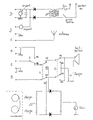
- the appended drawing illustrates by way of example an embodiment of the device in accordance with the present invention and which allows inter alia the following tests: In the workshop, using the cables provided for this purpose, connect: the top outlet (s) - car radio speakers, to socket A for a mono device, to sockets A and B for a stereo device, antenna C and low voltage D to the corresponding car radio sockets. Position the switches: E on El, F on FI, G on Gl. Connect the input of the power supply to the city alternating current. On a vehicle, the car radio to be controlled remains connected to the on-board battery for its supply and the device is not connected to the city alternating current. All other connections and switches remain as above.
- the operation of the switch G on GI then on G2 switches the internal speaker of the device successively on each of the two channels of the device tested.
- This original technique which thus makes it possible to test each channel separately, is more precise than the usual assembly with two speakers by which the two channels are heard simultaneously and combined. It is then difficult, if not impossible, to discern possible differences or anomalies from one channel compared to the other, differences which, even slight, appear clearly with the device object of the invention, due to the instantaneous nature of the switching.
- the precise control of balance, or balance, of the two channels is carried out by making the reader read the test cassette. With the device to be tested connected as described above, set switch E to E2. This maneuver replaces the internal speaker of the device with a circuit which integrates the phase signals from the two channels of the stereo device. The resulting signal is displayed on a galvanometer, or any other visual indicator.
- the operation of the balance control of the device under test makes it possible to determine the signal equalization point on the two channels, this point corresponding to the maximum deviation of the galvanometer, or to the maximum indication of any other visual indicator.
- the test cassette also makes it possible to highlight anomalies in the drive of the set tape reflecting, either by a wavy sound in the loudspeaker of the device in position El, or by an unstable maximum of the needle of the galvanometer in position E2 .
- This system for controlling the balance of the two channels of a stereophonic amplifier is similar to that described in the review "All Electronics" of September 1970, page 340, FIG. 2.
- the present invention does not use a transistor , thereby increasing the reliability of the device according to the invention.
- the Schody assembly described in the same article uses a different technique using a phase shifter, signal equality being indicated by a minimum on the galvanometer.
- the control of a loudspeaker is carried out by connecting it to the socket H of the device and by replacing it with the internal speaker of the latter by switching from F to F2, a car radio being connected and in operation on the device.
- the repeated operation of F, on FI then F2 makes it possible to quickly make a comparative test: internal speaker of the device / speaker under test.
- the two input circuits of the "control" sub-assembly may have either a common ground or isolated masses respectively. This second formula is necessary in the case of control of high-power stereophonic devices, of the booster type for example, whose output conductors have no common point.
- Fault diagnostics are carried out, in the workshop or directly on board the vehicle, by tests like those previously described or the substitution of elements of the device for those of the installation tested.
Landscapes
- Chemical & Material Sciences (AREA)
- Engineering & Computer Science (AREA)
- Combustion & Propulsion (AREA)
- Physics & Mathematics (AREA)
- General Physics & Mathematics (AREA)
- Fittings On The Vehicle Exterior For Carrying Loads, And Devices For Holding Or Mounting Articles (AREA)
- Testing Electric Properties And Detecting Electric Faults (AREA)
- Steering Control In Accordance With Driving Conditions (AREA)
- Vehicle Body Suspensions (AREA)
Claims (3)
Priority Applications (1)
| Application Number | Priority Date | Filing Date | Title |
|---|---|---|---|
| AT80401384T ATE11701T1 (de) | 1979-10-02 | 1980-10-01 | Vorrichtung zum kontrollieren und beurteilen von autoradios. |
Applications Claiming Priority (2)
| Application Number | Priority Date | Filing Date | Title |
|---|---|---|---|
| FR7924465 | 1979-10-02 | ||
| FR7924465A FR2468918A1 (fr) | 1979-10-02 | 1979-10-02 | Banc de controle et reglages pour auto-radios |
Publications (2)
| Publication Number | Publication Date |
|---|---|
| EP0027078A1 EP0027078A1 (de) | 1981-04-15 |
| EP0027078B1 true EP0027078B1 (de) | 1985-02-06 |
Family
ID=9230200
Family Applications (1)
| Application Number | Title | Priority Date | Filing Date |
|---|---|---|---|
| EP80401384A Expired EP0027078B1 (de) | 1979-10-02 | 1980-10-01 | Vorrichtung zum Kontrollieren und Beurteilen von Autoradios |
Country Status (4)
| Country | Link |
|---|---|
| EP (1) | EP0027078B1 (de) |
| AT (1) | ATE11701T1 (de) |
| DE (1) | DE3070118D1 (de) |
| FR (1) | FR2468918A1 (de) |
Families Citing this family (5)
| Publication number | Priority date | Publication date | Assignee | Title |
|---|---|---|---|---|
| US5450624A (en) * | 1993-01-07 | 1995-09-12 | Ford Motor Company | Method and apparatus for diagnosing amp to speaker connections |
| DE19544658C1 (de) * | 1995-11-30 | 1997-03-20 | Bosch Gmbh Robert | Verfahren zur Prüfung einer an einen Niederfrequenzverstärker angeschlossenen Impedanz und Anordnung dazu |
| US5815584A (en) * | 1996-11-08 | 1998-09-29 | Ford Motor Company | Automatic detection of shorted loudspeakers in automotive audio systems |
| CN101997625B (zh) * | 2009-08-10 | 2012-10-24 | 启碁科技股份有限公司 | 无线信号发射器及相关多媒体系统 |
| US8706278B2 (en) * | 2012-02-15 | 2014-04-22 | GM Global Technology Operations LLC | Non-bussed vehicle amplifier diagnostics |
Family Cites Families (1)
| Publication number | Priority date | Publication date | Assignee | Title |
|---|---|---|---|---|
| US3467867A (en) * | 1965-12-08 | 1969-09-16 | Gen Motors Corp | Apparatus for determining the operability of vehicle radio components |
-
1979
- 1979-10-02 FR FR7924465A patent/FR2468918A1/fr active Granted
-
1980
- 1980-10-01 DE DE8080401384T patent/DE3070118D1/de not_active Expired
- 1980-10-01 EP EP80401384A patent/EP0027078B1/de not_active Expired
- 1980-10-01 AT AT80401384T patent/ATE11701T1/de not_active IP Right Cessation
Also Published As
| Publication number | Publication date |
|---|---|
| FR2468918B1 (de) | 1982-11-12 |
| ATE11701T1 (de) | 1985-02-15 |
| FR2468918A1 (fr) | 1981-05-08 |
| DE3070118D1 (en) | 1985-03-21 |
| EP0027078A1 (de) | 1981-04-15 |
Similar Documents
| Publication | Publication Date | Title |
|---|---|---|
| US4670709A (en) | Portable audio system and audio cable continuity tester | |
| US6777952B2 (en) | Method and apparatus for testing cables | |
| US8041052B2 (en) | Circuit for priority selection of audio signals | |
| US4491694A (en) | Telephone to stereo amplifier interface coupling | |
| EP0027078B1 (de) | Vorrichtung zum Kontrollieren und Beurteilen von Autoradios | |
| US9077342B2 (en) | Circuit assembly for processing an electrical signal of a microphone | |
| CN114604173B (zh) | 检测系统、t-box及车辆 | |
| US20090086985A1 (en) | Apparatus and method for testing audio jacks of sound card | |
| CN106949902B (zh) | 导航语音故障解决方法、装置、设备及存储介质 | |
| US12545196B2 (en) | Splitter harness for vehicles with a proprietary interface port connector | |
| JPH052045A (ja) | 車載用検査装置 | |
| US4270151A (en) | Microphone mixer with predistortion indication | |
| US4385240A (en) | Audio device for motor vehicle | |
| JPS5921533Y2 (ja) | 車載用音響機器 | |
| FR2956525A1 (fr) | Systeme de connexion et simulateur utilisant un tel systeme de connexion | |
| Manual | ICBM | |
| JP3148532B2 (ja) | 電気機器の信号入力回路 | |
| EP4708922A1 (de) | Telemetrie- und kalibrierungsdaten eines lautsprechers | |
| US10906400B1 (en) | Vehicular radio and recording system | |
| JP2010019764A (ja) | 信号処理装置および信号処理装置の制御方法 | |
| EP2716066B1 (de) | Schaltungsanordnung zur verarbeitung eines elektrischen signals eines mikrofons | |
| JP3607674B2 (ja) | 車載用オーディオインターフェースアダプター | |
| Test | DIAGNOSIS AND TESTING | |
| US20050152556A1 (en) | Passive surround sound adapter | |
| Nathan | Back to basics audio |
Legal Events
| Date | Code | Title | Description |
|---|---|---|---|
| PUAI | Public reference made under article 153(3) epc to a published international application that has entered the european phase |
Free format text: ORIGINAL CODE: 0009012 |
|
| AK | Designated contracting states |
Designated state(s): AT BE CH DE GB IT LU NL |
|
| 17P | Request for examination filed |
Effective date: 19811014 |
|
| GRAA | (expected) grant |
Free format text: ORIGINAL CODE: 0009210 |
|
| AK | Designated contracting states |
Designated state(s): AT BE CH DE GB IT LI LU NL |
|
| PG25 | Lapsed in a contracting state [announced via postgrant information from national office to epo] |
Ref country code: NL Effective date: 19850206 Ref country code: IT Free format text: LAPSE BECAUSE OF FAILURE TO SUBMIT A TRANSLATION OF THE DESCRIPTION OR TO PAY THE FEE WITHIN THE PRESCRIBED TIME-LIMIT;WARNING: LAPSES OF ITALIAN PATENTS WITH EFFECTIVE DATE BEFORE 2007 MAY HAVE OCCURRED AT ANY TIME BEFORE 2007. THE CORRECT EFFECTIVE DATE MAY BE DIFFERENT FROM THE ONE RECORDED. Effective date: 19850206 Ref country code: AT Effective date: 19850206 |
|
| REF | Corresponds to: |
Ref document number: 11701 Country of ref document: AT Date of ref document: 19850215 Kind code of ref document: T |
|
| REF | Corresponds to: |
Ref document number: 3070118 Country of ref document: DE Date of ref document: 19850321 |
|
| NLV1 | Nl: lapsed or annulled due to failure to fulfill the requirements of art. 29p and 29m of the patents act | ||
| PG25 | Lapsed in a contracting state [announced via postgrant information from national office to epo] |
Ref country code: LU Free format text: LAPSE BECAUSE OF NON-PAYMENT OF DUE FEES Effective date: 19851031 |
|
| PLBE | No opposition filed within time limit |
Free format text: ORIGINAL CODE: 0009261 |
|
| STAA | Information on the status of an ep patent application or granted ep patent |
Free format text: STATUS: NO OPPOSITION FILED WITHIN TIME LIMIT |
|
| 26N | No opposition filed | ||
| PG25 | Lapsed in a contracting state [announced via postgrant information from national office to epo] |
Ref country code: LI Effective date: 19871031 Ref country code: CH Effective date: 19871031 |
|
| REG | Reference to a national code |
Ref country code: CH Ref legal event code: PL |
|
| PGFP | Annual fee paid to national office [announced via postgrant information from national office to epo] |
Ref country code: DE Payment date: 19881006 Year of fee payment: 9 |
|
| PG25 | Lapsed in a contracting state [announced via postgrant information from national office to epo] |
Ref country code: GB Effective date: 19891001 |
|
| PG25 | Lapsed in a contracting state [announced via postgrant information from national office to epo] |
Ref country code: BE Effective date: 19891031 |
|
| BERE | Be: lapsed |
Owner name: RONDIER JACQUES Effective date: 19891031 |
|
| GBPC | Gb: european patent ceased through non-payment of renewal fee | ||
| PG25 | Lapsed in a contracting state [announced via postgrant information from national office to epo] |
Ref country code: DE Effective date: 19900703 |