EP0027152A1 - Verfahren und Vorrichtung zur Übertragung periodischer elektrischen Signale mit sehr geringer Frequenzfehlertoleranz - Google Patents
Verfahren und Vorrichtung zur Übertragung periodischer elektrischen Signale mit sehr geringer Frequenzfehlertoleranz Download PDFInfo
- Publication number
- EP0027152A1 EP0027152A1 EP79200584A EP79200584A EP0027152A1 EP 0027152 A1 EP0027152 A1 EP 0027152A1 EP 79200584 A EP79200584 A EP 79200584A EP 79200584 A EP79200584 A EP 79200584A EP 0027152 A1 EP0027152 A1 EP 0027152A1
- Authority
- EP
- European Patent Office
- Prior art keywords
- frequency
- frequencies
- signals
- signal
- received
- Prior art date
- Legal status (The legal status is an assumption and is not a legal conclusion. Google has not performed a legal analysis and makes no representation as to the accuracy of the status listed.)
- Granted
Links
- 230000000737 periodic effect Effects 0.000 title claims abstract description 15
- 238000000034 method Methods 0.000 title claims abstract description 10
- 230000005540 biological transmission Effects 0.000 claims abstract description 23
- 239000003550 marker Substances 0.000 abstract 6
- 238000001228 spectrum Methods 0.000 abstract 1
- 230000010355 oscillation Effects 0.000 description 3
- 238000010586 diagram Methods 0.000 description 2
- 241001086826 Branta bernicla Species 0.000 description 1
- 239000004020 conductor Substances 0.000 description 1
- 230000000717 retained effect Effects 0.000 description 1
Images
Classifications
-
- H—ELECTRICITY
- H04—ELECTRIC COMMUNICATION TECHNIQUE
- H04L—TRANSMISSION OF DIGITAL INFORMATION, e.g. TELEGRAPHIC COMMUNICATION
- H04L27/00—Modulated-carrier systems
- H04L27/26—Systems using multi-frequency codes
-
- H—ELECTRICITY
- H04—ELECTRIC COMMUNICATION TECHNIQUE
- H04L—TRANSMISSION OF DIGITAL INFORMATION, e.g. TELEGRAPHIC COMMUNICATION
- H04L27/00—Modulated-carrier systems
Definitions
- the present invention relates to a method and device for transmitting periodic signals with very low tolerance for frequency error.
- the invention is applicable, for example, to equipment transmitting teletypewriter signals capable of being detected by vibrating plate detectors.
- vibrating plate detectors When such vibrating plate detectors have a natural frequency of approximately 1000 Hz, the allowable frequency error tolerance is substantially less than 10 Hz.
- the modulated frequency is used as a reference for demodulation on reception.
- the object of the present invention is a method which, even in the presence of drifts and other frequency errors such as calibration errors of local oscillators, makes it possible to transmit at each transmission time a single frequency chosen from a group of determined frequencies and to restore, on reception, standardized useful frequencies, for example those detectable by plate detectors vi brantes from a teletypewriter.
- Another object of the invention is to use for the transmission of the useful frequencies a band of frequencies shifted at a chosen location in the range of frequencies transmitted, for example at one end of the band allocated for transmitting speech in a system transmission of telephone communications.
- the method used to carry out the invention is a method in which signals are generated and transmitted and in which, on reception, the received signal is demodulated to reconstruct signals with useful frequencies characterized in that on transmission, generates periodic signals with determined frequencies offset from the signals with useful frequencies of values equal to those which one obtains or would obtain, if one modulates or modulates a subcarrier of frequency given by the useful frequencies and if one does not retain or do retained that one of the side bands of this subcarrier, in that one chooses one of the periodic signals at determined frequencies shifted by a fixed value of said subcarrier, to serve as signal for the start of messa-.
- the frequency of the signal at the start of the received message is measured, and in that a reference signal whose frequency is at the location of the receiver is generated shifted from this measured frequency by said fixed value and the periodic signals at predetermined frequencies received relating to the message preceded by the message start signal are demodulated with respect to this reference signal which becomes, for the signals received, the sub carrier of demodulation and which thus makes it possible to obtain the signals at useful frequencies.
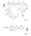
- FIG. 1 a diagram of a receiving device and, FIG. 2, a diagram of a transmitting device for teletypewriters.
- periodic signals at determined frequencies are chosen by the keys of a teletypewriter and transmitted during consecutive moments.
- the transmitted signals do not necessarily have to be useful frequency signals to which the vibrating plate detectors of the transmitting and receiving teletypewriters are sensitive.
- these transmitted signals hereinafter called periodic signals at determined frequencies born, can be shifted compared to the useful frequencies of values equal to those which one obtains or would obtain if one modulates or modulated a subcarrier of frequency given by the useful frequencies and if one retains or retains only one of the bands of this subcarrier.
- the useful frequencies are therefore not transmitted, although this can be done, but directly the periodic signals at determined frequencies offset from the signals at useful frequencies.
- one chooses one of the periodic signals at predetermined frequencies, offset by a fixed value of said subcarrier to serve as the message start signal.
- This fixed value is chosen such that the periodic signals at determined frequencies occupy a band located at a chosen location in a range of frequencies transmitted, for example, in the case of a system for transmitting telephone communications, at one of the ends of the range allocated to speech transmission.
- the range allocated to the transmission of speech extends from 300 to 3000 Hz and if the useful frequency signals which actuate the vibrating plate demodulators of the receiving teleprinter are included in the band from 800 to 1200 Hz, we choose signals at specific frequencies to be transmitted in the 2600 to 3000 Hz band, which still leaves the possibility of simultaneously transmitting speech.
- the message start signal chosen from among the signals at determined frequencies, for example 3000 Hz.
- This message start signal can also be an idle signal.
- the transmitted signals are received by the receiver ( Figure 1) and pass through an attenuator 1, a band filter 2 and a limiter 3 at the output of which a rectangular signal is collected.
- This rectangular signal is transformed in a low-pass filter 4 into a sinusoidal oscillation f o applied to a first input of a demodulator 5.
- the demodulator 5 is supplied on the other hand, by a reference signal fr applied to a second input . It then delivers signals of useful frequencies f u equal to the difference f r -f o .
- These useful frequency signals f u can activate the vibrating plates of a receiving teleprinter, not shown.
- the sinusoidal oscillations fo cannot. not be exactly the reproduction of the fre determined frequencies emitted due to various reasons such as the drift of certain circuit elements. However, these causes influence all frequencies in the transmitted band equally. On the other hand, the drifts and other causes vary only slowly over time so that a continuous transmission of a reference frequency is not necessary.
- the reference signal f r is equal to the subcarrier if no frequency error affects the transmission. In all other cases, it differs slightly. Indeed, it is obtained thanks to the transmission of the message start signal which on transmission measures for example 3000 Hz. When, after transmission, it is received at the first input of the demodulator 5, it may be that it is affected in example 15 Hz frequency error and that measures only 2985 Hz 15 Hz this error affects all frequencies in the attraction and band -. you between 2600 and 3000 Hz to compensate for this error, the signals.
- a high-pass filter 6 which transmits towards its output only the start of message signal, that is to say the frequency signals greater than for example 2970 Hz, if l maximum predictable error is less than 30 Hz.
- the signal at the output of the filter 6 is applied to a combined measuring device and oscillation generator 7 which can be preceded by a rectangular signal limiter or generator 8, in particular when the device 7 is a computer or microprocessor which measures the frequency of the signal at the output of filter 6 and generates a frequency equal to this measured frequency plus a fixed value, for example 800 Hz. If the frequency of the message start signal, measured by device 7 is 2985 Hz, the frequency of the reference signal generated by this same device 7 is 3785 Hz; it is applied to the second input of the demodulator 5.
- This demodulator 5 receives on the one hand, at the first input, the frequencies which, at transmission, occupied the band from 2600 to 3000 Hz and which at reception occupy the band from 2585 to 2985 Hz and on the other hand, at the second input, this reference frequency 3785 Hz with respect to which the demodulation is carried out. Consequently, the signals at useful frequencies detectable by the vibrating plates of a receiving teleprinter, not shown, sent on a conductor 9 then have frequencies in the band of 800 to 1200 Hz and this, independently of an initial error of frequency which could affect the received signals.
- the start of message signal can be sent in the form of an idle frequency, but it suffices to send this signal for, for example, a few fractions of a second at the start of each message.
- the generation of the old reference frequency is interrupted and replaced by the generation of a new reference frequency by adding to the measured frequency of the signal start of message the fixed value, in this case 800 Hz.
- the invention is applicable either in the case of conventional teletypewriter transmitting useful frequencies in the band 800 to 1200 Hz or in the case of teletypewriter directly transmitting offset frequencies, for example between 2600 and 3000 Hz.
- the teletypewriter transmits useful frequency signals in the band from 800 to 1200 Hz, these signals pass through an attenuator 10, and a modulator 11 where they modulate a subcarrier signal of 3800 Hz.
- the signals leaving the modulator 11 then pass through a filter 12 letting the band pass from 2600 to 3000 Hz before being emitted, for example, by modulating a carrier at higher frequency.
Landscapes
- Engineering & Computer Science (AREA)
- Computer Networks & Wireless Communication (AREA)
- Signal Processing (AREA)
- Digital Transmission Methods That Use Modulated Carrier Waves (AREA)
- Transmitters (AREA)
- Radar Systems Or Details Thereof (AREA)
Priority Applications (3)
| Application Number | Priority Date | Filing Date | Title |
|---|---|---|---|
| EP79200584A EP0027152B1 (de) | 1979-10-15 | 1979-10-15 | Verfahren und Vorrichtung zur Übertragung periodischer elektrischen Signale mit sehr geringer Frequenzfehlertoleranz |
| DE7979200584T DE2967698D1 (de) | 1979-10-15 | 1979-10-15 | Verfahren und vorrichtung zur uebertragung periodischer elektrischen signale mit sehr geringer frequenzfehlertoleranz. |
| AT79200584T ATE55857T1 (de) | 1979-10-15 | 1979-10-15 | Verfahren und vorrichtung zur uebertragung periodischer elektrischen signale mit sehr geringer frequenzfehlertoleranz. |
Applications Claiming Priority (1)
| Application Number | Priority Date | Filing Date | Title |
|---|---|---|---|
| EP79200584A EP0027152B1 (de) | 1979-10-15 | 1979-10-15 | Verfahren und Vorrichtung zur Übertragung periodischer elektrischen Signale mit sehr geringer Frequenzfehlertoleranz |
Publications (2)
| Publication Number | Publication Date |
|---|---|
| EP0027152A1 true EP0027152A1 (de) | 1981-04-22 |
| EP0027152B1 EP0027152B1 (de) | 1990-08-22 |
Family
ID=8186305
Family Applications (1)
| Application Number | Title | Priority Date | Filing Date |
|---|---|---|---|
| EP79200584A Expired - Lifetime EP0027152B1 (de) | 1979-10-15 | 1979-10-15 | Verfahren und Vorrichtung zur Übertragung periodischer elektrischen Signale mit sehr geringer Frequenzfehlertoleranz |
Country Status (3)
| Country | Link |
|---|---|
| EP (1) | EP0027152B1 (de) |
| AT (1) | ATE55857T1 (de) |
| DE (1) | DE2967698D1 (de) |
Cited By (1)
| Publication number | Priority date | Publication date | Assignee | Title |
|---|---|---|---|---|
| EP0144245A3 (de) * | 1983-12-07 | 1987-09-30 | Matsushita Electric Industrial Co., Ltd. | Sender- und Empfängersystem |
Families Citing this family (1)
| Publication number | Priority date | Publication date | Assignee | Title |
|---|---|---|---|---|
| RU2285344C2 (ru) * | 2004-10-14 | 2006-10-10 | Федеральное государственное унитарное предприятие "Воронежский научно-исследовательский институт связи" | Помехозащищенная система связи |
Citations (6)
| Publication number | Priority date | Publication date | Assignee | Title |
|---|---|---|---|---|
| FR1244379A (fr) * | 1959-09-14 | 1960-10-28 | Acec | Dispositif correcteur de fréquences |
| FR1511037A (fr) * | 1966-12-13 | 1968-01-26 | Montages Electr Atel | Dispositif de transmission par radio à haute sélectivité |
| US3573621A (en) * | 1967-03-06 | 1971-04-06 | Control Data Corp | Data format conversion and transmission system |
| US3577082A (en) * | 1969-03-05 | 1971-05-04 | Ibm | Carrier frequency phase-readjustment device |
| US3716790A (en) * | 1970-05-11 | 1973-02-13 | Lorain Electronics Corp | Single sideband system utilizing two tone modulation |
| GB2009541A (en) * | 1977-09-21 | 1979-06-13 | Post Office | >A method and apparatus for synchronizing waveforms |
-
1979
- 1979-10-15 EP EP79200584A patent/EP0027152B1/de not_active Expired - Lifetime
- 1979-10-15 AT AT79200584T patent/ATE55857T1/de not_active IP Right Cessation
- 1979-10-15 DE DE7979200584T patent/DE2967698D1/de not_active Expired - Lifetime
Patent Citations (6)
| Publication number | Priority date | Publication date | Assignee | Title |
|---|---|---|---|---|
| FR1244379A (fr) * | 1959-09-14 | 1960-10-28 | Acec | Dispositif correcteur de fréquences |
| FR1511037A (fr) * | 1966-12-13 | 1968-01-26 | Montages Electr Atel | Dispositif de transmission par radio à haute sélectivité |
| US3573621A (en) * | 1967-03-06 | 1971-04-06 | Control Data Corp | Data format conversion and transmission system |
| US3577082A (en) * | 1969-03-05 | 1971-05-04 | Ibm | Carrier frequency phase-readjustment device |
| US3716790A (en) * | 1970-05-11 | 1973-02-13 | Lorain Electronics Corp | Single sideband system utilizing two tone modulation |
| GB2009541A (en) * | 1977-09-21 | 1979-06-13 | Post Office | >A method and apparatus for synchronizing waveforms |
Non-Patent Citations (1)
| Title |
|---|
| IBM TECHNICAL DISCLOSURE BULLETIN, Vol. 6, No. 12, Mai 1964, New York US, E. HOPNER, et al. 'Digital gain and frequency control', pages 38 - 39 * |
Cited By (1)
| Publication number | Priority date | Publication date | Assignee | Title |
|---|---|---|---|---|
| EP0144245A3 (de) * | 1983-12-07 | 1987-09-30 | Matsushita Electric Industrial Co., Ltd. | Sender- und Empfängersystem |
Also Published As
| Publication number | Publication date |
|---|---|
| DE2967698D1 (de) | 1990-09-27 |
| EP0027152B1 (de) | 1990-08-22 |
| ATE55857T1 (de) | 1990-09-15 |
Similar Documents
| Publication | Publication Date | Title |
|---|---|---|
| EP0624959B1 (de) | FM-Empfänger mit einer Schaltung zur Überabtastung | |
| US5539770A (en) | Spread spectrum modulating apparatus using either PSK or FSK primary modulation | |
| JP2758211B2 (ja) | 周波数直接変調psk方式 | |
| EP0337644B1 (de) | Verfahren und Gerät zur Nachrichtenübertragung | |
| US7389055B1 (en) | DQPSK receiver phase control | |
| EP0466182A2 (de) | Intensitätsmodulierte optische Übertragungsvorrichtung | |
| JPH063512B2 (ja) | コヒーレント光通信用偏波ダイバーシティ光受信装置 | |
| US20070274713A1 (en) | System and method for subcarrier modulation as supervisory channel | |
| FR2681203A1 (fr) | Systeme de transmission optique, et emetteur et recepteur optiques. | |
| EP0718989B1 (de) | Faseroptische Heterodynübertragungsverbindung mit niedrigem Vorspannungsstrom | |
| KR960012796A (ko) | 광 신호 전송 장치, 광 신호 편광 변조 장치, 광 신호 전송 방법, 광 신호 편광 변조 방법 및 전송 시스템 | |
| JPH043540A (ja) | スペクトラム拡散通信装置 | |
| FR2515451A1 (fr) | Recepteur de donnees fm a modulation directe | |
| WO2005091532A1 (ja) | キャリア残留型信号の生成方法及びその装置 | |
| JPH053458A (ja) | 光双方向伝送方法と装置 | |
| US5832027A (en) | Spread spectrum modulating and demodulating apparatus for transmission and reception of FSK and PSK signals | |
| WO2022174656A1 (zh) | 一种相干检测方法、装置及系统 | |
| EP0541406A1 (de) | Verfahren und Gerät zur Übertragung zweier Informationen über eine Spreizspektrumverbindung | |
| EP0014244A1 (de) | Verfahren und Vorrichtung zur Prüfung eines Frequenzsynthesators in einem HF-Modem | |
| EP0027152A1 (de) | Verfahren und Vorrichtung zur Übertragung periodischer elektrischen Signale mit sehr geringer Frequenzfehlertoleranz | |
| FR2482804A1 (fr) | Recepteur radioelectrique a modulation de frequence | |
| CA2029052C (en) | Tone spacing and power level monitor for fsk lightwave systems | |
| EP0715434A1 (de) | Detektionsgerät zum Erkennung eines digital modulierten Trägers | |
| US7133621B1 (en) | Optical communication with phase encoding and phase shifting | |
| EP0011015B1 (de) | Digitaler regenerativer Richtfunkverstärker und solche Verstärker enthaltendes Übertragungsnetz |
Legal Events
| Date | Code | Title | Description |
|---|---|---|---|
| PUAI | Public reference made under article 153(3) epc to a published international application that has entered the european phase |
Free format text: ORIGINAL CODE: 0009012 |
|
| AK | Designated contracting states |
Designated state(s): AT BE CH DE FR GB IT LU NL SE |
|
| 17P | Request for examination filed |
Effective date: 19810704 |
|
| RAP1 | Party data changed (applicant data changed or rights of an application transferred) |
Owner name: ATELIERS DE CONSTRUCTIONS ELECTRIQUES DE CHARLEROI |
|
| GRAA | (expected) grant |
Free format text: ORIGINAL CODE: 0009210 |
|
| AK | Designated contracting states |
Kind code of ref document: B1 Designated state(s): AT BE CH DE FR GB IT LU NL SE |
|
| PG25 | Lapsed in a contracting state [announced via postgrant information from national office to epo] |
Ref country code: SE Free format text: THE PATENT HAS BEEN ANNULLED BY A DECISION OF A NATIONAL AUTHORITY Effective date: 19900822 Ref country code: NL Effective date: 19900822 Ref country code: IT Free format text: LAPSE BECAUSE OF FAILURE TO SUBMIT A TRANSLATION OF THE DESCRIPTION OR TO PAY THE FEE WITHIN THE PRESCRIBED TIME-LIMIT;WARNING: LAPSES OF ITALIAN PATENTS WITH EFFECTIVE DATE BEFORE 2007 MAY HAVE OCCURRED AT ANY TIME BEFORE 2007. THE CORRECT EFFECTIVE DATE MAY BE DIFFERENT FROM THE ONE RECORDED. Effective date: 19900822 Ref country code: GB Effective date: 19900822 Ref country code: AT Effective date: 19900822 |
|
| REF | Corresponds to: |
Ref document number: 55857 Country of ref document: AT Date of ref document: 19900915 Kind code of ref document: T |
|
| REF | Corresponds to: |
Ref document number: 2967698 Country of ref document: DE Date of ref document: 19900927 |
|
| PG25 | Lapsed in a contracting state [announced via postgrant information from national office to epo] |
Ref country code: LU Free format text: LAPSE BECAUSE OF NON-PAYMENT OF DUE FEES Effective date: 19901031 |
|
| NLV1 | Nl: lapsed or annulled due to failure to fulfill the requirements of art. 29p and 29m of the patents act | ||
| GBV | Gb: ep patent (uk) treated as always having been void in accordance with gb section 77(7)/1977 [no translation filed] | ||
| RAP2 | Party data changed (patent owner data changed or rights of a patent transferred) |
Owner name: ALCATEL BELL-SDT S.A. |
|
| PLBE | No opposition filed within time limit |
Free format text: ORIGINAL CODE: 0009261 |
|
| STAA | Information on the status of an ep patent application or granted ep patent |
Free format text: STATUS: NO OPPOSITION FILED WITHIN TIME LIMIT |
|
| 26N | No opposition filed | ||
| PGFP | Annual fee paid to national office [announced via postgrant information from national office to epo] |
Ref country code: FR Payment date: 19920911 Year of fee payment: 14 |
|
| PGFP | Annual fee paid to national office [announced via postgrant information from national office to epo] |
Ref country code: CH Payment date: 19920928 Year of fee payment: 14 |
|
| PGFP | Annual fee paid to national office [announced via postgrant information from national office to epo] |
Ref country code: BE Payment date: 19920930 Year of fee payment: 14 |
|
| PGFP | Annual fee paid to national office [announced via postgrant information from national office to epo] |
Ref country code: DE Payment date: 19921222 Year of fee payment: 14 |
|
| PG25 | Lapsed in a contracting state [announced via postgrant information from national office to epo] |
Ref country code: CH Effective date: 19931031 Ref country code: BE Effective date: 19931031 |
|
| BERE | Be: lapsed |
Owner name: ALCATEL BELL-SDT S.A. Effective date: 19931031 |
|
| PG25 | Lapsed in a contracting state [announced via postgrant information from national office to epo] |
Ref country code: FR Effective date: 19940630 |
|
| REG | Reference to a national code |
Ref country code: CH Ref legal event code: PL Ref country code: CH Ref legal event code: AUV Free format text: LE BREVET CI-DESSUS EST TOMBE EN DECHEANCE , FAUTE DE PAIEMENT, DE LA 15 ANNUITE. |
|
| PG25 | Lapsed in a contracting state [announced via postgrant information from national office to epo] |
Ref country code: DE Effective date: 19940701 |
|
| REG | Reference to a national code |
Ref country code: FR Ref legal event code: ST |
|
| APAH | Appeal reference modified |
Free format text: ORIGINAL CODE: EPIDOSCREFNO |