EP0027200B1 - Dispositif pour planchéier des excavations - Google Patents
Dispositif pour planchéier des excavations Download PDFInfo
- Publication number
- EP0027200B1 EP0027200B1 EP80105881A EP80105881A EP0027200B1 EP 0027200 B1 EP0027200 B1 EP 0027200B1 EP 80105881 A EP80105881 A EP 80105881A EP 80105881 A EP80105881 A EP 80105881A EP 0027200 B1 EP0027200 B1 EP 0027200B1
- Authority
- EP
- European Patent Office
- Prior art keywords
- collar
- actuator assembly
- shank
- elements
- driveshaft
- Prior art date
- Legal status (The legal status is an assumption and is not a legal conclusion. Google has not performed a legal analysis and makes no representation as to the accuracy of the status listed.)
- Expired
Links
Images

Classifications
-
- E—FIXED CONSTRUCTIONS
- E02—HYDRAULIC ENGINEERING; FOUNDATIONS; SOIL SHIFTING
- E02D—FOUNDATIONS; EXCAVATIONS; EMBANKMENTS; UNDERGROUND OR UNDERWATER STRUCTURES
- E02D17/00—Excavations; Bordering of excavations; Making embankments
- E02D17/06—Foundation trenches ditches or narrow shafts
- E02D17/08—Bordering or stiffening the sides of ditches trenches or narrow shafts for foundations
- E02D17/083—Shoring struts
-
- B—PERFORMING OPERATIONS; TRANSPORTING
- B66—HOISTING; LIFTING; HAULING
- B66C—CRANES; LOAD-ENGAGING ELEMENTS OR DEVICES FOR CRANES, CAPSTANS, WINCHES, OR TACKLES
- B66C1/00—Load-engaging elements or devices attached to lifting or lowering gear of cranes or adapted for connection therewith for transmitting lifting forces to articles or groups of articles
- B66C1/10—Load-engaging elements or devices attached to lifting or lowering gear of cranes or adapted for connection therewith for transmitting lifting forces to articles or groups of articles by mechanical means
- B66C1/62—Load-engaging elements or devices attached to lifting or lowering gear of cranes or adapted for connection therewith for transmitting lifting forces to articles or groups of articles by mechanical means comprising article-engaging members of a shape complementary to that of the articles to be handled
- B66C1/66—Load-engaging elements or devices attached to lifting or lowering gear of cranes or adapted for connection therewith for transmitting lifting forces to articles or groups of articles by mechanical means comprising article-engaging members of a shape complementary to that of the articles to be handled for engaging holes, recesses, or abutments on articles specially provided for facilitating handling thereof
-
- B—PERFORMING OPERATIONS; TRANSPORTING
- B66—HOISTING; LIFTING; HAULING
- B66C—CRANES; LOAD-ENGAGING ELEMENTS OR DEVICES FOR CRANES, CAPSTANS, WINCHES, OR TACKLES
- B66C23/00—Cranes comprising essentially a beam, boom, or triangular structure acting as a cantilever and mounted for translatory of swinging movements in vertical or horizontal planes or a combination of such movements, e.g. jib-cranes, derricks, tower cranes
- B66C23/54—Cranes comprising essentially a beam, boom, or triangular structure acting as a cantilever and mounted for translatory of swinging movements in vertical or horizontal planes or a combination of such movements, e.g. jib-cranes, derricks, tower cranes with pneumatic or hydraulic motors, e.g. for actuating jib-cranes on tractors
Definitions
- This invention relates to an apparatus for encasing, propping or erecting falseworks in excavations and the like.
- an apparatus which includes a crane set up for moving over the ground surface (either truck- mounted or self-propelled) and extendible struts which are rigged and removed from the job site by means of the crane boom and which, also by means of the crane boom, are operated to take their extended operative positions and retracted inoperative positions.
- a crane set up for moving over the ground surface (either truck- mounted or self-propelled) and extendible struts which are rigged and removed from the job site by means of the crane boom and which, also by means of the crane boom, are operated to take their extended operative positions and retracted inoperative positions.
- This invention sets out to provide an apparatus of the same general type as above, which is considerably simplified, such that its manufacture and use become economically advantageous and its range of application much wider, even when employed in small width excavations.
- an apparatus for encasing excavations comprising a movable crane equipped with a boom, and extendible struts adapted for rigging on the job site and for handling by said crane boom, said crane boom carrying an actuator assembly for extending and retracting said struts, characterized in that each strut comprises a tubular main body in the shape of an inverted 'T" and defining a gripping collar at the leg of said 'T", a pair of elements mounted for sliding to and fro along the respective limbs of said 'T", the sliding movement of said elements being controlled through a nut-and-screw drive, said elements terminating at the outer ends thereof in plate-like frames for propping the excavation walls, and a driveshaft driving said nut-and-screw drive through a bevel gear pair, said driveshaft being journalled at said leg of said 'T" and projecting above it with a clutch member, said actuator assembly being intended to overlie said leg and being provided with clamping jaw
- the numeral 1 generally designates a crane, carried on a platform 2; the platform 2 is integrally mounted on a carrier, either of the wheeled or track type, that is a carrier of the type of a truck or earthmover, said carrier being schematically indicated at 3.
- the crane can be moved over the ground, along either side of the excavation, or even astride the excavation if the carrier gauge allows.
- the platform 2 is provided with extendible feet 4 which have a steadying function and are intended for engaging the ground while the crane is being operated.
- the crane 1 comprises an upright or column 5 rotatably mounted on the platform 2 and controllable to take a desired angular position by means of a pair of jacks 6.
- the column 5 defines a coaxial jack 7 which is part of an articulated quadrilateral, having an extendible member in the jack, further including a rod 8 and plate 9.
- a coaxial jack 7 which is part of an articulated quadrilateral, having an extendible member in the jack, further including a rod 8 and plate 9.
- the amount of extension of the other segment 10b of the crane boom can be varied by means of the jack 12.
- To the segment 10b the segment 13a of the crane jib is articulated, the inclination angle of the jib being adjustable through the jack 14; the jack 15 is operative to change the extent of extension of the other segment 13b from the crane jib.
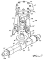
- the actuator assembly 18 comprises a tubular body 19, which is suspended at the top from the support 17 at an offset position and with the interposition of a series of compression springs 20 uniformly angularly distributed.
- the eccentricity of the actuator assembly 18 with respect to the jib 13a-b enables struts 21 to be actuated, which struts are arranged in the excavation or trench at different heights on the same vertical plane; the limited extent of oscillation permitted by the springs 20, through a greater or smaller compression thereof, to the body 19 with respect to the support 17, enables, as will be explained hereinafter, a correct engagement of the actuator assembly with a strut 21.
- the body 19 defines at the top a flange 19a, whereto threaded ties 22 are attached which are passed with some clearance through the support 17; in the space thus left between the support and flange, compression springs 20 are interposed for which the threaded ties function as guides.
- the flange 19a is engaged by screws 19b which secure to the body 19 a tubular bell- like element 19c, wherein a lower shoulder 17a of the support 17 is inserted; this shoulder tends to remain in contact with the upper edge of the bell 19c by virtue of the springs 20 being interposed between that shoulder and tabs 19d on the body 19, the springs being guided by bolt ties 22 intervening between the tabs 19d and the upper edge of the bell 19c and passed with some clearance through the shoulder 17a.
- a reversible motor 23 is provided the shaft 24 whereof is oriented downwards and has attached thereto an externally splined tubular element 25.
- the tubing 25 is tangentially locked to the shaft 24 by means of keys, whilst the axial lock is obtained by means of a cap 26, which is clamped against the end of said shaft and covers at the bottom the splines of the tubing.
- a sleeve 27 is axially slidable but not rotatable on the tubing 25; in fact the top portion of the sleeve is splined internally, and the bottom travel limit for this portion, and accordingly for the sleeve as a whole, is established by the edge of the cap 26.
- the widened bottom portion of the sleeve 27 has a pair of cutouts 28, which being located at diametrically opposed positions, extend axially to said bottom portion and are open downwardly. Such cutouts are operative to accommodate, as will be explained hereinafter, lugs 29 which are located diametrically opposite the top of the shaft 30, which shaft projects above each strut 21 from a collar 31.
- the collar 31 of the strut is adapted for being clamped against the lower edge of the body 19 of the actuator assembly, the top of the shaft 30 penetrating said body: if the lugs 29 are not aligned with the cutouts 28, then the sleeve 27 will be raised by sliding along the tubing 25, to then sink again by gravity as soon as said cutouts, as the motor 23 is operated, are located on the vertical of the lugs 29 and ready for engagement therewith.
- Each strut 21 comprises a main body in the shape of an inverted "T" and of tubular configuration: the limbs of the "T” are formed by two prismatic tubings 36 which extend from a central box 37, wherefrom there extends upwardly a short tubing 38 which constitutes the leg of the "T” and terminates at the top in the collar 31.
- the shaft 30 is journaled at 38 and terminated with a bevel gear 39 located inside the box 37.
- an element 40 also prismatic and tubular, which, at the proximity of the box 37, is provided with a nut 41 rigid therewith.
- the two nuts 41 are oppositely threaded and coupled with mating screw portions 42, formed on an axle the middle portion 42a whereof is mounted for rotation in the box 37, which axle carries within said box a bevel gear 43 keyed thereto and in mesh engagement with the gear 39 on the driveshaft 30.
- the free ends of the portions 42 are provided with a shoulder 44, adapted for limiting the outward travel of the elements 40 from the tubings 36.
- each element 40 is closed by a ring 45 and has a head 46, which is threaded to the ring and defines outwardly an inside threaded shank 46a.
- a ring 47 which is a part of a bowl-like member located centrally to a plate-like frame 48, which frame takes a transversal lay to the strut and is intended for a force fit and holding against the walls of the excavation (to the outside of the frame there being attached planks not shown in the drawings).
- the ring 47 has an outwardly diverging and inwardly converging shape; between this ring and the ring 45, there is interposed a powerful compression spring 49 which urges the ring 47 against the shoulder 50, which is also outwardly divergent and is attached to the shank 46a by means of screws.
- a powerful compression spring 49 which urges the ring 47 against the shoulder 50, which is also outwardly divergent and is attached to the shank 46a by means of screws.
- the heads 46 are formed with transversal through holes for the insertion of locking pin members therein of the related end of any extension element.
Landscapes
- Engineering & Computer Science (AREA)
- Mining & Mineral Resources (AREA)
- Mechanical Engineering (AREA)
- General Engineering & Computer Science (AREA)
- Paleontology (AREA)
- Civil Engineering (AREA)
- General Life Sciences & Earth Sciences (AREA)
- Structural Engineering (AREA)
- Life Sciences & Earth Sciences (AREA)
- Basic Packing Technique (AREA)
- Earth Drilling (AREA)
- Jib Cranes (AREA)
- Electrical Discharge Machining, Electrochemical Machining, And Combined Machining (AREA)
- Farming Of Fish And Shellfish (AREA)
- Measuring Pulse, Heart Rate, Blood Pressure Or Blood Flow (AREA)
Claims (6)
Priority Applications (1)
| Application Number | Priority Date | Filing Date | Title |
|---|---|---|---|
| AT80105881T ATE5337T1 (de) | 1979-10-12 | 1980-09-29 | Apparat zum verschalen von ausschachtungen. |
Applications Claiming Priority (2)
| Application Number | Priority Date | Filing Date | Title |
|---|---|---|---|
| IT03507/79A IT1126024B (it) | 1979-10-12 | 1979-10-12 | Attrezzatura per armare scavi e simili |
| IT350779 | 1979-10-12 |
Publications (3)
| Publication Number | Publication Date |
|---|---|
| EP0027200A2 EP0027200A2 (fr) | 1981-04-22 |
| EP0027200A3 EP0027200A3 (en) | 1981-11-04 |
| EP0027200B1 true EP0027200B1 (fr) | 1983-11-16 |
Family
ID=11108665
Family Applications (1)
| Application Number | Title | Priority Date | Filing Date |
|---|---|---|---|
| EP80105881A Expired EP0027200B1 (fr) | 1979-10-12 | 1980-09-29 | Dispositif pour planchéier des excavations |
Country Status (5)
| Country | Link |
|---|---|
| US (1) | US4370079A (fr) |
| EP (1) | EP0027200B1 (fr) |
| AT (1) | ATE5337T1 (fr) |
| DE (1) | DE3065625D1 (fr) |
| IT (1) | IT1126024B (fr) |
Families Citing this family (13)
| Publication number | Priority date | Publication date | Assignee | Title |
|---|---|---|---|---|
| GB2231352A (en) * | 1989-05-03 | 1990-11-14 | Mabey Hire Co | Strut-panel joint in a strong-box |
| GB2231353A (en) * | 1989-05-03 | 1990-11-14 | Mabey Hire Co | Cantilever springs in a strong-box |
| BE1003896A3 (nl) * | 1990-02-26 | 1992-07-07 | Bonneux Hydraulic Systems Nv | Vrachtwagenlaadkraan. |
| US5688324A (en) * | 1994-07-15 | 1997-11-18 | Dainippon Screen Mfg. Co., Ltd. | Apparatus for coating substrate |
| US7048471B2 (en) * | 2000-04-05 | 2006-05-23 | Maksim Kadiu | Shoring device |
| US6821057B1 (en) * | 2000-04-05 | 2004-11-23 | Maksim Kadiu | Magnetic shoring device |
| US7056067B2 (en) * | 2003-10-03 | 2006-06-06 | Max Kadiu | Trench shoring device |
| EP1857401A1 (fr) * | 2006-05-19 | 2007-11-21 | Bromma Conquip Ab | Ensemble palonniers et moyens de positionnement |
| US20110305529A1 (en) * | 2010-06-09 | 2011-12-15 | Riggle Jr John | Trench shoring apparatuses and methods |
| US9033619B2 (en) * | 2012-12-14 | 2015-05-19 | John Riggle, JR. | Trench shoring apparatuses |
| US10399829B2 (en) * | 2014-09-11 | 2019-09-03 | Jacques Tranchero | Crane for lifting and transporting loads |
| GB2579598B (en) * | 2018-12-05 | 2023-08-02 | Secure Ground Solutions Ltd | Trench shoring apparatus and its method of use |
| CN112814700B (zh) * | 2021-01-05 | 2023-03-31 | 深圳市天翊建设有限公司 | 一种盾区基坑围护结构以及施工工艺 |
Family Cites Families (12)
| Publication number | Priority date | Publication date | Assignee | Title |
|---|---|---|---|---|
| US909808A (en) * | 1907-11-25 | 1909-01-12 | John D Cook | Wall-supporting device for trenches. |
| US2922283A (en) * | 1958-05-19 | 1960-01-26 | Fred S Porter | Excavation shoring devices |
| DE1873321U (de) * | 1961-11-03 | 1963-06-06 | Gottfried Schubert G M B H Str | Innenschalungsvorrichtung zum herstellen von rohrfoermigen, fugenlosen kanalschuessen, insbesondere aus beton. |
| DE1855084U (de) * | 1962-02-19 | 1962-07-12 | Josef Krings | Vorrichtung zum verlegen von rohren od. dgl. in graeben. |
| FR1535655A (fr) * | 1967-06-28 | 1968-08-09 | Entpr Bourdin & Chausse | Appareil pour assurer la protection des ouvriers dans les travaux en tranchées |
| GB1341881A (en) * | 1971-02-16 | 1973-12-25 | Paget E J | Apparatus for shoring trenches |
| US3792782A (en) * | 1971-12-10 | 1974-02-19 | Programmed & Remote Syst Corp | Grapple assembly |
| US3788086A (en) * | 1972-04-13 | 1974-01-29 | Charter Enterprises Inc | Protective barrier |
| US3905632A (en) * | 1972-05-01 | 1975-09-16 | Transcinor Inc | Pallet head loader |
| US3777902A (en) * | 1972-06-05 | 1973-12-11 | Auto Place Inc | Workpiece-gripping reach and turnover attachment |
| DE2513310A1 (de) * | 1974-04-05 | 1975-10-09 | Siler Ag | Innenverschalung |
| FR2398847A1 (fr) * | 1977-07-29 | 1979-02-23 | Fercos De Pizzirani Cesare | Equipement pour l'etresillonnement de tranchees |
-
1979
- 1979-10-12 IT IT03507/79A patent/IT1126024B/it active
-
1980
- 1980-09-29 US US06/191,966 patent/US4370079A/en not_active Expired - Lifetime
- 1980-09-29 DE DE8080105881T patent/DE3065625D1/de not_active Expired
- 1980-09-29 AT AT80105881T patent/ATE5337T1/de not_active IP Right Cessation
- 1980-09-29 EP EP80105881A patent/EP0027200B1/fr not_active Expired
Also Published As
| Publication number | Publication date |
|---|---|
| US4370079A (en) | 1983-01-25 |
| ATE5337T1 (de) | 1983-12-15 |
| EP0027200A3 (en) | 1981-11-04 |
| EP0027200A2 (fr) | 1981-04-22 |
| IT1126024B (it) | 1986-05-14 |
| IT7903507A0 (it) | 1979-10-12 |
| DE3065625D1 (en) | 1983-12-22 |
Similar Documents
| Publication | Publication Date | Title |
|---|---|---|
| EP0027200A2 (fr) | Dispositif pour planchéier des excavations | |
| CA1333388C (fr) | Dispositif permettant d'ajouter et de positionner des tubes a partir d'endroits differents selectionnes | |
| US10611616B2 (en) | Aerial device with quick-coupling implement | |
| US3832918A (en) | Breakout wrench | |
| EA029885B1 (ru) | Гидрофицированная мобильная буровая установка | |
| US6641347B2 (en) | Pole extractor | |
| US2589080A (en) | Power-operated telescoping mast and braces | |
| US1507776A (en) | Earth-boring machine | |
| CN106241622A (zh) | 移动式吊机 | |
| US20080190633A1 (en) | Hydraulic Attachment for Skid Steer Loaders | |
| DE69825528T2 (de) | Vorrichtung zur Handhabung von Bohrstangen | |
| JPH03137392A (ja) | ウエルポイント等の引抜装置 | |
| US4757622A (en) | Portable power shovel | |
| CN217205402U (zh) | 一种新型土木工程施工用混凝土抹平装置 | |
| JPH0635399U (ja) | 多機能トンネル施工装置 | |
| AU2012101722B4 (en) | Apparatus for modifying a pole | |
| US3092260A (en) | Back-hitch gaintry | |
| DE9206391U1 (de) | Arbeitsgerät zum Abbruch oder Aufbau von Mauern | |
| CN110158591B (zh) | 桩锤组件及具有该桩锤组件的打桩机 | |
| CN115653652B (zh) | 一种锚杆机辅助装置 | |
| CN109162757B (zh) | 一种防止倾倒自动扶正式装岩机 | |
| US10077172B1 (en) | Interchangeable jib tool | |
| JPS6033198Y2 (ja) | トンネルセグメントの解体装置 | |
| US4485570A (en) | Apparatus for mounting a drilling machine on an excavator bucket | |
| IT201800005910A1 (it) | Macchina di perforazione, procedimento di assemblaggio, e kit per una macchina di perforazione. |
Legal Events
| Date | Code | Title | Description |
|---|---|---|---|
| PUAI | Public reference made under article 153(3) epc to a published international application that has entered the european phase |
Free format text: ORIGINAL CODE: 0009012 |
|
| AK | Designated contracting states |
Designated state(s): AT BE CH DE FR GB NL SE |
|
| PUAL | Search report despatched |
Free format text: ORIGINAL CODE: 0009013 |
|
| RHK1 | Main classification (correction) |
Ipc: E02D 17/08 |
|
| AK | Designated contracting states |
Designated state(s): AT BE CH DE FR GB NL SE |
|
| 17P | Request for examination filed |
Effective date: 19820422 |
|
| GRAA | (expected) grant |
Free format text: ORIGINAL CODE: 0009210 |
|
| AK | Designated contracting states |
Designated state(s): AT BE CH DE FR GB LI NL SE |
|
| REF | Corresponds to: |
Ref document number: 5337 Country of ref document: AT Date of ref document: 19831215 Kind code of ref document: T |
|
| REF | Corresponds to: |
Ref document number: 3065625 Country of ref document: DE Date of ref document: 19831222 |
|
| ET | Fr: translation filed | ||
| PLBE | No opposition filed within time limit |
Free format text: ORIGINAL CODE: 0009261 |
|
| STAA | Information on the status of an ep patent application or granted ep patent |
Free format text: STATUS: NO OPPOSITION FILED WITHIN TIME LIMIT |
|
| 26N | No opposition filed | ||
| PGFP | Annual fee paid to national office [announced via postgrant information from national office to epo] |
Ref country code: BE Payment date: 19900920 Year of fee payment: 11 |
|
| PGFP | Annual fee paid to national office [announced via postgrant information from national office to epo] |
Ref country code: GB Payment date: 19900921 Year of fee payment: 11 |
|
| PGFP | Annual fee paid to national office [announced via postgrant information from national office to epo] |
Ref country code: SE Payment date: 19900924 Year of fee payment: 11 |
|
| PGFP | Annual fee paid to national office [announced via postgrant information from national office to epo] |
Ref country code: FR Payment date: 19900926 Year of fee payment: 11 |
|
| PGFP | Annual fee paid to national office [announced via postgrant information from national office to epo] |
Ref country code: AT Payment date: 19900928 Year of fee payment: 11 |
|
| PGFP | Annual fee paid to national office [announced via postgrant information from national office to epo] |
Ref country code: NL Payment date: 19900930 Year of fee payment: 11 |
|
| PGFP | Annual fee paid to national office [announced via postgrant information from national office to epo] |
Ref country code: DE Payment date: 19901004 Year of fee payment: 11 |
|
| PGFP | Annual fee paid to national office [announced via postgrant information from national office to epo] |
Ref country code: CH Payment date: 19901008 Year of fee payment: 11 |
|
| PG25 | Lapsed in a contracting state [announced via postgrant information from national office to epo] |
Ref country code: GB Effective date: 19910929 Ref country code: AT Effective date: 19910929 |
|
| PG25 | Lapsed in a contracting state [announced via postgrant information from national office to epo] |
Ref country code: SE Effective date: 19910930 Ref country code: LI Effective date: 19910930 Ref country code: CH Effective date: 19910930 Ref country code: BE Effective date: 19910930 |
|
| BERE | Be: lapsed |
Owner name: FERCOS DI PIZZIRANI CESARE Effective date: 19910930 |
|
| PG25 | Lapsed in a contracting state [announced via postgrant information from national office to epo] |
Ref country code: NL Effective date: 19920401 |
|
| NLV4 | Nl: lapsed or anulled due to non-payment of the annual fee | ||
| GBPC | Gb: european patent ceased through non-payment of renewal fee | ||
| PG25 | Lapsed in a contracting state [announced via postgrant information from national office to epo] |
Ref country code: FR Effective date: 19920529 |
|
| REG | Reference to a national code |
Ref country code: CH Ref legal event code: PL |
|
| PG25 | Lapsed in a contracting state [announced via postgrant information from national office to epo] |
Ref country code: DE Effective date: 19920602 |
|
| REG | Reference to a national code |
Ref country code: FR Ref legal event code: ST |
|
| EUG | Se: european patent has lapsed |
Ref document number: 80105881.9 Effective date: 19920408 |