EP0027431B1 - Distributeur, en particulier pour savon liquide - Google Patents
Distributeur, en particulier pour savon liquide Download PDFInfo
- Publication number
- EP0027431B1 EP0027431B1 EP80810314A EP80810314A EP0027431B1 EP 0027431 B1 EP0027431 B1 EP 0027431B1 EP 80810314 A EP80810314 A EP 80810314A EP 80810314 A EP80810314 A EP 80810314A EP 0027431 B1 EP0027431 B1 EP 0027431B1
- Authority
- EP
- European Patent Office
- Prior art keywords
- reservoir
- main body
- piston
- pushed
- cylinder
- Prior art date
- Legal status (The legal status is an assumption and is not a legal conclusion. Google has not performed a legal analysis and makes no representation as to the accuracy of the status listed.)
- Expired
Links
Images




Classifications
-
- A—HUMAN NECESSITIES
- A47—FURNITURE; DOMESTIC ARTICLES OR APPLIANCES; COFFEE MILLS; SPICE MILLS; SUCTION CLEANERS IN GENERAL
- A47K—SANITARY EQUIPMENT; ACCESSORIES THEREFOR, e.g. TOILET ACCESSORIES
- A47K5/00—Holders or dispensers for soap, toothpaste or the like
- A47K5/06—Dispensers for soap
- A47K5/12—Dispensers for soap for liquid or pasty soap
- A47K5/1202—Dispensers for soap for liquid or pasty soap dispensing dosed volume
- A47K5/1204—Dispensers for soap for liquid or pasty soap dispensing dosed volume by means of a rigid dispensing chamber and pistons
Definitions
- the present invention relates to dispensers for fluent material, and particularly to the type that are normally wall-mounted and used, e.g. beside sinks, to dispense a quantity of liquid soap at one touch of an actuator by the intended user.
- dispensers for supplying liquid soap in a predetermined volume by one touch of an actuator have been widely employed in washrooms, etc. Most of them have been designed such that: the dispenser main body or vessel and a liquid soap reservoir have been integrally constructed and so that a fresh supply of liquid soap has been poured into the reservoir, e.g. from a drum, when the soap supply in the reservoir has been substantially used-up.
- solidified soap adheres about the liquid soap reservoir portion of such a dispenser and the pouring inlet-outlet thereof and such adhered soap has not been easily wiped- off from the outside.
- these conventional dispensers have provided a difficulty of complete cleaning and also have given an unfavorable aesthetic appearance.
- a button is normally employed, but a careless pushing of the button has been sufficient to release the coupling of the reservoir and valve seats of the dispenser and to permit the liquid soap to leak at this site and hence provide a drawback that as the dispenser continues to be operated the predetermined volume of the liquid soap is not conveniently supplied and more leakage occurs each time the actuator is pushed.
- the British patent specification No. 711,630 describes a liquid dispenser which comprises a chambered body with a top socket for receiving the neck of a receptacle holding the substance to be dispensed.
- the capped receptacle which is separate from the chambered body or the socket, is screwed into the socket, whereby the cap is punctured by a cap opener provided in the socket.
- the used receptacle has to be thrown away.
- the loosening of the recipient from the distributor is to be carried out in a rather com- licated way.
- the Swiss patent specification No. 285438 describes equally a liquid dispenser which comprises a body into which a neck of a separate receptacle containing the liquid substance is inserted.
- the receptacle is mounted in the apparatus in its inverted position.
- the claws of the receptacle enter into the claws of the socket whereafter the receptacle can be fixed by its turning in the socket.
- the receptacle is secured against accidental turning in the socket by means of a pin.
- the present invention has been provided to overcome such drawbacks in the prior art.
- One of the objects of this invention is to provide a soap dispenser of the type designed to have a detachable soap reservoir which can be exchanged for a new one full of liquid soap for further dispensing, thereby providing easy handling and maintenance, and also permitting easy washing and cleaning of the dispenser without need for detaching the dispenser from the wall and the like, causing no delay for obtaining one charge of the liquid soap, nor supplying any excessive amount of liquid soap.
- Another object of the present invention is to provide a soap dispenser with a locking means for the releasing button which releases the locking state of the dispenser main body and the liquid soap reservoir wherein said locking means is designed so that a careless pushing of the releasing button does not cause the release of the locking state, release of the locking state being possible only when the locking means is intentionally unlocked so that the soap reservoir may be exchanged.
- the reservoir is replaced by pushing in a resilient release, but the resilient release is preferably normally provided with a stop which must first be moved out of the way. This is to prevent the user from accidentally disconnecting the reservoir when what is really wanted is a dispensation of soap. Should the reservoir be disconnected, pushing in and releasing the plunger will not result in the first outlet valve opening, because pressure will not be lowered in the metering chamber when the plunger is released.
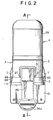
- the dispenser 1 includes an upright open top/closed bottom cylindrical main body 2 that has an open forward end/closed rear end cylinder 12 formed in the bottom wall thereof.
- a through hole 14 is formed through the bottom wall of the main body 2 into the chamber defined within the cylinder 12, and this hole 14 is perimetrically spacedly surrounded by a first valve seat, shown having the form of an upwardly opening groove.
- the cylinder 12 is provided with a tubular boss 16 which projects downwardly and forwardly to provide a housing for a second outlet valve 48.
- the boss 16 includes an internal longitudinal passage 16a in communication with the metering chamber within the cylinder 12, which passage 16a includes a series of two, stepped annular shoulders 19, 18 and a band of internal threading 17.
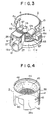
- the main body 2 may be made fully or partly from synthetic resin and is shown including a tubular sidewall 5, in which, at two diametrically-opposed (e.g. left and right side) locations, is provided with U-shaped slots 6 which thus partially separate from the tubular sidewall 5 two tongue-shaped releasing button bodies 6a which have resilient shank portions with enlarged, outwardly protruding releasing buttons 7 at their lower ends. Spaced above each button 7, each resilient shank 6a is provided with a generally horizontally-elongated, lozenge-shaped protuberance 8 of generally triangular vertical cross-sectional shape.
- each protuberance 8 is so located on the respective tongue 6a so that when the respective button 7 is pushed in, the respective protuberance 8 is pushed in, albeit to a lesser extent.
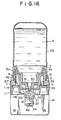
- each protuberance 8 has a sloping upper surface and a horizontal lower surface, as shown in Figure 16.
- a protruding flange 9 of the inverted U-shape At the front of the main body, surrounding the top and part of the sides of the cylinder 12 is a protruding flange 9 of the inverted U-shape, providing a supporting frame.
- stop ridges 26 At the inside top front of the supporting frame 9 are provided stop ridges 26; and in the sidewalls above the cylinder 12 are provided hinge pintle bosses 27 for journalling the pivotable actuator 56.
- the main body 2 sidewall 5 is externally provided with a support bracket boss 10, which is used for removably securing the dispenser to a support bracket 61, which is, in turn, wall mounted. See Figure 15.
- the bracket 61 can be conveniently mounted with the rest of the device not in the way, and once mounted to the wall need not be detached to detach the rest of the dispenser from the wall.
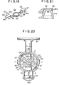
- the bottom wall 2a of the main body 2 is provided with a structure 11 comprising two respective fan-shaped upward protrusions of generally inverted U-shaped cross-sectional shape. See Figure 21.
- Each such protrusion includes an upwardly presented surface 11 b that is fan-shaped in top plan view ( Figure 20).
- the bottom wall 11 further includes a flared, frusto-conically-curved outer skirt 11 a, which provides a depending skirt for the main body 2 sidewall 5.
- the skirt 11 a extends arcuately from one side of the supporting frame 9 all the way round the sidewall 5 to the other side of the supporting frame 9. See Figure 1, 15 and 16.
- the cylinder 12 internally, has a rear portion 12b of smaller internal diameter and a forward portion 12a of larger internal diameter. At the top near the rear, closed end, the cylinder 12 is internally provided with a longitudinally extending guide rail 12c, which is received in a groove 21 in the plunger piston 20. See Figure 6, 15, 17 and 18.
- the piston 20 is slidably received in the cylinder 12.
- the piston 20 preferably is a tubular member with a closed rear end and a sidewall provided so as to correspond in diameter to the smaller diameter portion 12a of the cylinder bore.
- the piston 20 is formed with two longitudinal grooves which extend all the way to the rear of the piston 20. These are a first groove 21 which runs along the top of the piston sidewall and a second one 22 which runs along the bottom of the piston sidewall.
- the piston sidewall, also opposite the smaller diameter portion of the cylinder is provided with a circumferential groove 20a in which is received an O-ring 23 for sealing between the piston and cylinder forwardly of the grooves 21, 22.
- the groove 21 is shown being longer than the groove 22. As shown in Figure 17, the grooves are preferably long enough so that even when the piston 20 is pushed all the way in, the groove 21 remains in communication with the outlet side of the first outlet valve 31 etc. and the groove 22 remains in communication with the inlet side of the second outlet valve 48, etc.
- the piston At its forward end, the piston is fitted with a ring-shaped flange 24, on which at the nine o'clock and three o'clock positions are provided half moon-shaped flanges 25, the inner faces of which are flush with the inside of the piston 20.
- the flanges 25 protrude forwards further than the flange 24 does.
- a compression coil spring 60 is coaxially provided on the shank of the piston with a forward end against the back of the flange 24 and a rear end against the annular shoulder formed in the cylinder 12 at the point where the larger internal diameter portion 12a adjoins the smaller internal diameter portion 12b, so that when the piston is pushed in from the Figure 18 disposition thereof to the Figure 17 disposition thereof, and released, the spring 60 will push the piston 12 back out to the Figure 18 disposition thereof.
- the lever 56 is narrow enough at the top to fit between the sides of the supporting frame member 9, where it is pivotally secured at 58 to the main body 2.
- the lever 56 is shallowly, broadly U-shaped in transverse cross-sectional shape, so as to have a broad central flange and two rearwardly projecting opposite side flanges 56b, which in the upper part of the lever 56 are enlarged at 57 to provide hinge brackets which are pivotally connected with the bosses 27 at 58.
- the lower end region of the lever is angled forwards, i.e. towards the user, and provided with an e.g. semi-circular, enlarged push piece which may be covered with non-slip rubber or the like.
- the first outlet valve seat 13 is partially formed in the bottom wall 2a of the main body 2, particularly the hole 14 surrounded by an annular thickened portion having an upwardly opening perimetrically extending groove.
- the hole 14 preferably has a frusto-conically curved sidewall which tapers downwards.
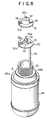
- the reservoir 4 for containing the liquid that is to be dispensed comprises a container body 28 having an end wall, a sidewall, a shoulder and a tubular neck. When disconnected from the device 1, the reservoir 4 usually would have the orientation shown in Figure 5. In use, as shown in Figures 1, 2 and 15-18 the reservoir 4 is inverted so as to be oriented neck- downwards/end wall-upwards. The neck is externally threaded at 32.
- the shoulder includes a series of two, stepped annular, axially-facing flanges 28a, 28b, with a frusto-conically curved transitional surface portion extending between them.
- the reservoir 4 further includes a suction cap 30 comprising a disk-shaped flat flange 30a, the outer diameter of which is about equal to that of the end of container body neck, so that the suction cap 30 may be butted against the end of the neck and not protrude radially therebeyond.
- the outer face of the suction cap is provided with a hollow-generally cylindrically shaped protuberance 33 having a half-moon-shaped radial projection 33a formed at one side.
- a protuberance 33 having a half-moon-shaped radial projection 33a formed at one side.
- a spike 29 having a frustoconical base portion and a generally round-ended cylindrical tip portion 29a.
- axial grooves 34 are formed in the conical base portion of the spike 29.
- a tubular boss 35 is formed on the flat flange 30a.
- the bore of the boss 35 communicates through the flat flange 30a.
- the boss 35 is, on the inner face of the flat flange 30a, fitted with an extension tube 59 which, when the suction cap is fitted to the container body neck, projects within the container body to near the container end wall.
- the first outlet valve 31 comprises a body, e.g. made of soft synthetic rubber or the like, having a resilient quality. It includes a flat circular disk portion 31 a of the same diameter as the disk 30a, and having an eccentrically- located opening 38 positioned to fit over the tubular boss 35 when the flanges 30a and 31 a are brought into coaxial adjacency. Axially centrally, the disk 31 a is provided with a frusto- conical boss 36, tipped with a smaller frusto- conical boss 37, to provide an annular, axially facing shoulder adapted to annularly, sealingly project, in an intermediate ring-shaped region 36a, into the valve seat annular groove 15. The boss 37 is open at the outer end at 37a. The reverse side of the valve 31 from the projection 36, 37 is recessed, complementary to the shape of the parts 33, 33a, 29, 29a of the suction cap 30, so as to receive such parts as the two disks 30a, 31 a are brought together.
- the parts 30, 31 are held together on the end of the container body 28, by screwing on the cap 3, that is shown by itself in Figure 4.
- the cap 3 includes a cylindrical sidewall, which is internally threaded at 46 and a ring-shaped end wall 46a having a large central opening through which the projections on the suction cap 3 and first valve 31 protrude.
- the cap is secured on the container body by threading the threads 46 onto the threads 32.
- the sidewall flares to provide a downwardly tapering surface 45, then projects radially outwards to provide an annular, axially facing flange, and then doubles back downwards to provide an outer cylindrical skirt 39.
- the skirt 39 at two diametrically opposed positions is provided with generally squared-off notches 40, 41 opening through the lower edge of the skirt 39. These are sized, shaped and located to fit over the supporting frame 9 and the supporting member 10, respectively.
- the lower edge of the skirt 39 is provided with two more squared-off notches 42, sized, shaped and positioned to fit over the releasing buttons 7.
- the skirt 39 Spaced above the notch 42, the skirt 39 is provided on each side with an angularly elongated oval slot 43, sized, shaped and positioned to allow the corresponding lozenge-shaped protuberance 8 to protrude outwards therethrough.
- the parts 31, 30, 59 and 4 are assembled together from their Figure 5 positions and secured together by the threading on the cap 3 until the surface 45 abuts the corresponding surface of the container and the cap end wall 46a squeezes the flanges 30a, 31 a against the end of the container neck.
- the assembled container is secured to the dispenser main body by inverting the assembled container from its Figure 5 disposition and lowering its lower end into the well shown in Figure 3, until the notch 40 receives the supporting frame 9, the notch 41 receives the supporting member 10, the notches 42 receive the releasing buttons 7 and the protuberances 8 snap into the slots 43. This act also pulls the first valve 31 tightly against the seat 13 at 36a, 15.
- the well of the main body 2 is provided with an upwardly directed boss, comprising the aforementioned valve seat 13.
- the present invention provides a stop member for preventing accidental disconnection of the reservoir 4 from the main body 2.
- the stop member 62 is shown by itself in Figure 19. It comprises a fitting having a central ring-shaped flange portion 63 which fits around the valve seat 13 and two diametrically-oppositely directed arms 64 which slant upwards at 65, then have a horizontal flange portion at 66, and an outer, downwardly flaring lip at 68.
- the flanges 66 rest on the surfaces 11 b in the well of the main body as shown in Figure 20, and the lips 68 protrude out through and down from the same slots 42 as the releasing buttons 7.
- the flanges 66 are somewhat narrower than the slots 42, so that the fixture 62 may be moved angularly between two extremes.
- the lugs 67 In one angular extreme of the stop member fixture 62 (shown in full lines in Figure 20), the lugs 67 back up the resilient pieces 6a, preventing the buttons 7 from being pushed-in sufficiently to release the protuberances 8 from the slots 43. In the other angular extreme (shown in dashed lines in Figure 20), the lugs 67 are angularly clear of the resilient pieces, so that the buttons 7 may be pushed in to release the reservoir from the main body. In use, the fixture 62 is kept in its full line latching condition so that a user cannot accidentally disconnect the reservoir from the main body by pressing in the releasing buttons 7. The only time the fixture 62 is brought to the dashed line position is to permit intentional disassembly and replacement or refilling of the reservoir.
- the skirt 11a a on the main body 2 is provided with an external bead 69 which backs-up the inner sides of the tabs 62a of the bent portion 68 in order to keep the fixture 62 in either position in which it is intentionally placed.
- the device shown is completed by the structure of the second outlet valve 48, parts of which are shown by themselves in Figures 11-14.
- the valve body 47 having disk 47a, frusto-conical part 49, grooves 50 and central projection portions 51 corresponding to the structures 30a, 29, 29a of the first valve.
- the surrounding portion of the second valve 48 comprising a flange 52, a frusto-conical tubular portion 53 and an open outer end cylindrical portion 53a. This part compares to the part 31 shown in Figure 5.
- the parts 47 and 48 are assembled to one another and mounted in the second valve seat 16 as shown i.e. in Figure 17, against the stepped shoulders 19, 18 shown therein.
- annular cap 54 which compares with the cap 3.
- the cap 54 is externally threaded at 55 to screw into the threads 17.
- the outer annular skirt portion 54a of the cap 54 is internally flared towards the outer lower end.
- Each valve body is ported through the grooves in its tapered portion, e.g. at 34, 50, but the tapering tubular flap which surrounds each valve body normally resiliently engages the projection 29a or 53a to prevent flow through that valve.
- the tapering tubular flap which surrounds each valve body normally resiliently engages the projection 29a or 53a to prevent flow through that valve.
- a quantum of liquid e.g. liquid soap from the dispenser by pushing-in on the handle 56a.
- the piston 20 As the piston 20 is pushed in, the volume of space in the chamber behind the piston is decreased, which increases the pressure within the chamber sufficiently to cause the thin resilient portion of the second valve at 53a to move radially outwards temporarily.
- the first valve 31 remains closed.
- the resilient portion 53a recovers and the second valve closes, having dispensed a quantum of the liquid.
- the spring 60 recovers, pushing out the piston 20.
- This enlarges the volume of the chamber thus lowering the pressure on the downstream side of the valve 31.
- the annular flap 37 temporarily resiliently distends away from the central protuberance 29a, permitting a next quantum of liquid to flow through the channels 30 of the first outlet valve 31 into the dispensing chamber, ready for the next user's push on the operating lever push piece 56a.
- the resilient part 37 recovers its smaller diameter and the first valve closes. Since both the valves 31 and 48 are one-way valves, the second outlet valve 48 remains closed as the dispensing chamber is refilling through the first valve 31.
- the vent tube 59 which extends up to near the top of the container 28, i.e. to above the liquid level therein permits the head space above the liquid to recover atmospheric pressure, since it lies outside the main body/reservoir seal provided at 13, 36a.
- stop member 62 Although use of the stop member 62 is preferred, it and its function may be simply omitted, yet the other advantages of the device of the present invention may be enjoyed. If someone should push in the operating lever 56 after the releasing buttons 7 have been pushed in, because the sealing connection at 36a, 13 will have been disrupted, upon releasing the lever 56, the pressure in the dispensing chamber at 21, 22, 16a within the cylinder 12 ahead of the piston 20 will not lower, so no more liquid will come out of the reservoir 4.
Landscapes
- Health & Medical Sciences (AREA)
- Public Health (AREA)
- Containers And Packaging Bodies Having A Special Means To Remove Contents (AREA)
- Closures For Containers (AREA)
Claims (2)
Applications Claiming Priority (4)
| Application Number | Priority Date | Filing Date | Title |
|---|---|---|---|
| JP143171/79U | 1979-10-16 | ||
| JP14317179U JPS5663395U (fr) | 1979-10-16 | 1979-10-16 | |
| JP11565480U JPS5745919Y2 (fr) | 1980-08-15 | 1980-08-15 | |
| JP115654/80U | 1980-08-15 |
Publications (3)
| Publication Number | Publication Date |
|---|---|
| EP0027431A2 EP0027431A2 (fr) | 1981-04-22 |
| EP0027431A3 EP0027431A3 (en) | 1981-07-01 |
| EP0027431B1 true EP0027431B1 (fr) | 1984-07-11 |
Family
ID=26454132
Family Applications (1)
| Application Number | Title | Priority Date | Filing Date |
|---|---|---|---|
| EP80810314A Expired EP0027431B1 (fr) | 1979-10-16 | 1980-10-15 | Distributeur, en particulier pour savon liquide |
Country Status (4)
| Country | Link |
|---|---|
| US (1) | US4360130A (fr) |
| EP (1) | EP0027431B1 (fr) |
| DE (1) | DE3068541D1 (fr) |
| DK (1) | DK148851C (fr) |
Cited By (2)
| Publication number | Priority date | Publication date | Assignee | Title |
|---|---|---|---|---|
| GB2278102A (en) * | 1993-05-21 | 1994-11-23 | Sprintvest Corp Nv | Dispensing apparatus |
| WO1996021387A1 (fr) * | 1995-01-09 | 1996-07-18 | Sprintvest Corporation N.V. | Distributeur de savon pliant |
Families Citing this family (65)
| Publication number | Priority date | Publication date | Assignee | Title |
|---|---|---|---|---|
| US4477000A (en) * | 1979-05-10 | 1984-10-16 | Europtool Trust | Apparatus for forming portions of soap foam |
| US4493440A (en) * | 1983-08-08 | 1985-01-15 | United States Borax & Chemical Corporation | Wall-mounted soap dispenser |
| US4673109A (en) * | 1985-10-18 | 1987-06-16 | Steiner Company, Inc. | Liquid soap dispensing system |
| DE3744483A1 (de) * | 1987-02-20 | 1988-09-01 | Suevia Haiges Kg | Portionsdosierer fuer fluessigkeitsabgabeeirichtungen, insbesondere fuer tiertraenken |
| DE8702590U1 (de) * | 1987-02-20 | 1987-04-09 | Suevia Haiges GmbH & Co, 7125 Kirchheim | Portionsdosierer für Flüssigkeitsabgabeeinrichtungen, insbesondere für Tiertränken |
| US4972978A (en) * | 1988-12-13 | 1990-11-27 | Georgia-Pacific Corporation | Dispenser having an improved metering chamber |
| US5975360A (en) * | 1991-05-20 | 1999-11-02 | Ophardt; Heiner | Capped piston pump |
| US5165577A (en) * | 1991-05-20 | 1992-11-24 | Heiner Ophardt | Disposable plastic liquid pump |
| US5676277A (en) * | 1991-05-20 | 1997-10-14 | Ophardt; Heiner | Disposable plastic liquid pump |
| US5489044A (en) * | 1991-05-20 | 1996-02-06 | Hygiene-Technik Inc. | Method of preparing replaceable liquid soap reservoir |
| US5282552A (en) * | 1991-05-20 | 1994-02-01 | Hygiene-Technik Inc. | Disposable plastic liquid pump |
| US5435465A (en) * | 1992-04-28 | 1995-07-25 | El-Amin; Hassan A. | Hygiene device |
| US5289949A (en) * | 1992-06-22 | 1994-03-01 | Chesebrough-Pond's Usa Co., Division Of Conopco, Inc. | Multi-cavity dispensing refill cartridge |
| US5332124A (en) * | 1993-05-17 | 1994-07-26 | Chesebrough-Pond's, Usa Co., A Division Of Conopco, Inc. | Multi-cavity dispensing refill cartridge |
| US5335827A (en) * | 1992-12-22 | 1994-08-09 | Chesebrough-Pond's Usa Co., A Division Of Conopco, Inc. | Multi-cavity dispensing refill cartridge |
| GB9526391D0 (en) * | 1995-12-22 | 1996-02-21 | Diversey Equipment Technologie | Dispenser |
| US6012613A (en) * | 1998-09-24 | 2000-01-11 | Chen; Yi-Chen | Extruding mechanism for auto dispenser |
| USD417111S (en) | 1999-02-11 | 1999-11-30 | Chester Labs, Inc. | Hinged dispenser housing |
| US6152330A (en) * | 1999-02-11 | 2000-11-28 | Chester Labs, Inc. | Hinged dispenser housing |
| US6516976B2 (en) * | 2000-12-19 | 2003-02-11 | Kimberly-Clark Worldwide, Inc. | Dosing pump for liquid dispensers |
| US6543651B2 (en) | 2000-12-19 | 2003-04-08 | Kimberly-Clark Worldwide, Inc. | Self-contained viscous liquid dispenser |
| US6540117B2 (en) | 2001-03-30 | 2003-04-01 | Kimberly-Clark Worldwide, Inc. | Dosing pump for liquid dispensers |
| US6832701B2 (en) * | 2002-04-05 | 2004-12-21 | Johnsondiversey, Inc. | Self metering dispensing device |
| GB0208806D0 (en) * | 2002-04-17 | 2002-05-29 | Rieke Corp | Dispenser pumps |
| US6926212B1 (en) * | 2003-04-07 | 2005-08-09 | George Glass | Device for adding soap to a water inlet |
| US7389893B2 (en) * | 2003-09-10 | 2008-06-24 | Rieke Corporation | Inverted dispensing pump |
| US7325704B2 (en) * | 2003-09-10 | 2008-02-05 | Rieke Corporation | Inverted dispensing pump with vent baffle |
| JP2005211145A (ja) * | 2004-01-27 | 2005-08-11 | Somei:Kk | 液体取出装置 |
| US7278554B2 (en) | 2004-05-10 | 2007-10-09 | Chester Labs, Inc. | Hinged dispenser housing and adaptor |
| US7654417B2 (en) * | 2004-06-28 | 2010-02-02 | Aluta, Inc. | Refillable product dispenser and system |
| CA2505812C (fr) * | 2004-08-12 | 2013-04-09 | Gotohti.Com Inc. | Ressort en cantilever |
| CA2477584C (fr) * | 2004-08-12 | 2011-07-26 | Hygiene-Technik Inc. | Distributeur jetable |
| US7270250B2 (en) * | 2004-08-30 | 2007-09-18 | Hygiene-Tecknik Inc. | Disposable dispenser |
| US7328819B2 (en) * | 2004-09-27 | 2008-02-12 | Kimberly-Clark Worldwide, Inc. | Self-contained liquid dispenser with a spray pump mechanism |
| DE102005006845A1 (de) * | 2005-02-14 | 2006-08-17 | Stockhausen Gmbh | Spender |
| GB0801249D0 (en) * | 2008-01-24 | 2008-02-27 | Dagenais Yannick | Fluid dispenser |
| US9433960B2 (en) * | 2008-09-01 | 2016-09-06 | Rieke Corporation | Liquid dosing devices |
| GB0815881D0 (en) | 2008-09-01 | 2008-10-08 | Rieke Corp | Liquid dosing devices |
| GB0912065D0 (en) | 2009-07-10 | 2009-08-19 | Reckitt & Colman Overseas | A fluid delivery system |
| US20110155766A1 (en) * | 2009-12-28 | 2011-06-30 | Hurley Timothy R | Mountable hand sanitizer station |
| US8418889B2 (en) * | 2010-01-11 | 2013-04-16 | Rieke Corporation | Inverted dispenser pump with liquid inlet cup valve |
| GB201000601D0 (en) | 2010-01-14 | 2010-03-03 | Rieke Corp | Pump dispensers |
| US8714413B2 (en) | 2010-03-10 | 2014-05-06 | Mary Elizabeth Coleman Fuqua | Mouthwash dispenser |
| US20110220683A1 (en) * | 2010-03-10 | 2011-09-15 | Mary Elizabeth Coleman Fuqua | Mouthwash Dispenser |
| GB201011143D0 (en) | 2010-07-01 | 2010-08-18 | Rieke Corp | Dispensers |
| GB201011144D0 (en) | 2010-07-01 | 2010-08-18 | Rieke Corp | Dispensers |
| US8708006B2 (en) | 2010-08-31 | 2014-04-29 | Gary A. Martin | Liquid container refilling system and method |
| US20130320043A1 (en) * | 2012-05-30 | 2013-12-05 | Gojo Industries, Inc. | Double acting valve for liquid pumps |
| US9084514B1 (en) * | 2012-06-06 | 2015-07-21 | Eric L. Elswick | Foot scrubbing apparatus |
| US20140054320A1 (en) * | 2012-08-23 | 2014-02-27 | Gojo Industries, Inc. | Off-axis inverted dispensers and refill units |
| US9038862B2 (en) * | 2013-01-23 | 2015-05-26 | Gojo Industries, Inc. | Pumps with container vents |
| US9307871B2 (en) * | 2012-08-30 | 2016-04-12 | Gojo Industries, Inc. | Horizontal pumps, refill units and foam dispensers |
| US9179808B2 (en) * | 2012-08-30 | 2015-11-10 | Gojo Industries, Inc. | Horizontal pumps, refill units and foam dispensers |
| MX358783B (es) | 2012-08-31 | 2018-09-04 | Arminak & Ass Llc | Formador de espuma por compresion invertida. |
| US9648992B2 (en) | 2013-12-19 | 2017-05-16 | Gojo Industries, Inc. | Pumps with vents to vent inverted containers and refill units having non-collapsing containers |
| CA2935987A1 (fr) * | 2014-01-15 | 2015-07-23 | Gojo Industries, Inc. | Pompes a sorties coudees, unites de remplissage et distributeurs comprenant des sorties coudees |
| WO2015127338A1 (fr) | 2014-02-24 | 2015-08-27 | Gojo Industries, Inc. | Récipients non repliables mis à l'air libre, récipients de re-remplissage rechargeables, distributeurs et unités de re-remplissage |
| WO2015179555A1 (fr) | 2014-05-20 | 2015-11-26 | Gojo Industries, Inc. | Systemes d'administration de fluide en deux parties |
| CA2956212C (fr) | 2014-07-30 | 2023-03-28 | Gojo Industries, Inc. | Unites ventilees de recharge et distributeurs presentant des unites ventilees de recharge |
| US10022023B2 (en) * | 2015-04-07 | 2018-07-17 | Vi-Jon, Inc. | Dispenser assembly |
| US20180132671A1 (en) | 2015-05-22 | 2018-05-17 | Clay Callicoat | Liquid product pump devices, systems, and methods of using the same |
| CA3066420C (fr) * | 2015-07-23 | 2023-03-07 | William J. Schalitz | Distributeur de savon jetable |
| WO2017034947A1 (fr) * | 2015-08-25 | 2017-03-02 | Rieke Corporation | Distributeur à pompe présentant une interface à poignée et une ventilation |
| EP3977905B1 (fr) | 2017-07-07 | 2024-10-09 | GOJO Industries, Inc. | Système de distribution |
| US11596269B2 (en) * | 2020-01-21 | 2023-03-07 | Kerrick Patterson | Liquid dispensing container and housing assembly |
Family Cites Families (11)
| Publication number | Priority date | Publication date | Assignee | Title |
|---|---|---|---|---|
| US1187474A (en) * | 1913-02-15 | 1916-06-13 | Rexine Company | Liquid-dispensing machine. |
| CH101580A (de) * | 1922-08-17 | 1923-10-01 | Heusser & Bosshardt | Seifenspender. |
| US2605021A (en) * | 1948-07-16 | 1952-07-29 | Churchill Henry Winsto Spencer | Dispenser for an inverted container with means for locking said container thereto and a self-closing outlet element |
| CH285438A (fr) * | 1948-07-16 | 1952-09-15 | Churchill Henry Winston S | Appareil pour distribuer des substances pâteuses et liquides. |
| GB711630A (en) * | 1951-11-27 | 1954-07-07 | Churchill Henry Winston S | Improvements relating to apparatus for dispensing pastes, liquids and other substances |
| US2772817A (en) * | 1952-03-01 | 1956-12-04 | Robert J Jauch | Dispensing pumps |
| US2825334A (en) * | 1953-08-07 | 1958-03-04 | Sr John Leo Kas | Hypodermic syringe for livestock |
| CH331376A (fr) * | 1955-08-12 | 1958-07-15 | Newton Chambers & Company Limi | Appareil pour dispenser une substance coulante |
| US3160329A (en) * | 1963-02-26 | 1964-12-08 | Radic Frank | Dispensing device |
| DE2121739A1 (de) | 1971-05-03 | 1972-11-09 | Metallwerke Adolf Hopf KG, 8860 Nördlingen | Sicherheits-Kappenverschluß für Gefäße mit Hals |
| US3848776A (en) * | 1972-12-19 | 1974-11-19 | Corco Inc | Disposable reservoir package for liquid-dispenser having valve and operating float |
-
1980
- 1980-10-15 US US06/197,214 patent/US4360130A/en not_active Expired - Lifetime
- 1980-10-15 DK DK436280A patent/DK148851C/da not_active IP Right Cessation
- 1980-10-15 EP EP80810314A patent/EP0027431B1/fr not_active Expired
- 1980-10-15 DE DE8080810314T patent/DE3068541D1/de not_active Expired
Cited By (3)
| Publication number | Priority date | Publication date | Assignee | Title |
|---|---|---|---|---|
| GB2278102A (en) * | 1993-05-21 | 1994-11-23 | Sprintvest Corp Nv | Dispensing apparatus |
| WO1996021387A1 (fr) * | 1995-01-09 | 1996-07-18 | Sprintvest Corporation N.V. | Distributeur de savon pliant |
| AU707860B2 (en) * | 1995-01-09 | 1999-07-22 | Deb Ip Limited | Collapsible soap dispenser |
Also Published As
| Publication number | Publication date |
|---|---|
| US4360130A (en) | 1982-11-23 |
| DK148851B (da) | 1985-10-28 |
| DK148851C (da) | 1986-04-21 |
| EP0027431A2 (fr) | 1981-04-22 |
| DK436280A (da) | 1981-04-17 |
| EP0027431A3 (en) | 1981-07-01 |
| DE3068541D1 (en) | 1984-08-16 |
Similar Documents
| Publication | Publication Date | Title |
|---|---|---|
| EP0027431B1 (fr) | Distributeur, en particulier pour savon liquide | |
| AU2011273199B2 (en) | Outlet attachment for a dispenser | |
| US4582227A (en) | Pump dispenser assembly | |
| US11857126B2 (en) | Theft deterrent dispenser and mounting assembly | |
| US5725132A (en) | Dispenser with snap-fit container connection | |
| US5826755A (en) | Liquid dispenser with selectably attachable actuator | |
| US4356848A (en) | Dispenser assembly | |
| AU768226B2 (en) | Compact fluid pump | |
| US5439144A (en) | Liquid soap dispensing system | |
| US20080053568A1 (en) | Slider valve fitment and collar | |
| JPH01153477A (ja) | ペースト状物質用の補給器 | |
| US3042267A (en) | Liquid dispensing device | |
| US20220330681A1 (en) | Dispenser with replaceable inner container | |
| US2702957A (en) | Valved closure | |
| US4679714A (en) | Unit dose liquid dispenser | |
| US20030116586A1 (en) | Toothpaste dispensing unit | |
| US2199947A (en) | Dispensing nozzle | |
| EP0599459B1 (fr) | Pompe distributrice | |
| CA1144118A (fr) | Debiteur de savon | |
| WO1997005043A9 (fr) | Distributeur rechargable, pour pate dentifrice | |
| WO1997005043A1 (fr) | Distributeur rechargable, pour pate dentifrice | |
| JP2004298804A (ja) | 液体噴出器 | |
| EP1383705B1 (fr) | Systeme d'injecteur de liquide | |
| CN112674576A (zh) | 一种可拆卸且可调节出水量的新型饮料容器 | |
| JPH09254989A (ja) | 二液混合容器 |
Legal Events
| Date | Code | Title | Description |
|---|---|---|---|
| PUAI | Public reference made under article 153(3) epc to a published international application that has entered the european phase |
Free format text: ORIGINAL CODE: 0009012 |
|
| AK | Designated contracting states |
Designated state(s): BE CH DE FR GB IT LI LU NL |
|
| PUAL | Search report despatched |
Free format text: ORIGINAL CODE: 0009013 |
|
| AK | Designated contracting states |
Designated state(s): BE CH DE FR GB IT LI LU NL |
|
| 17P | Request for examination filed |
Effective date: 19810710 |
|
| ITF | It: translation for a ep patent filed | ||
| GRAA | (expected) grant |
Free format text: ORIGINAL CODE: 0009210 |
|
| AK | Designated contracting states |
Designated state(s): BE CH DE FR GB IT LI LU NL |
|
| REF | Corresponds to: |
Ref document number: 3068541 Country of ref document: DE Date of ref document: 19840816 |
|
| ET | Fr: translation filed | ||
| PLBE | No opposition filed within time limit |
Free format text: ORIGINAL CODE: 0009261 |
|
| STAA | Information on the status of an ep patent application or granted ep patent |
Free format text: STATUS: NO OPPOSITION FILED WITHIN TIME LIMIT |
|
| 26N | No opposition filed | ||
| PGFP | Annual fee paid to national office [announced via postgrant information from national office to epo] |
Ref country code: FR Payment date: 19910911 Year of fee payment: 12 |
|
| PGFP | Annual fee paid to national office [announced via postgrant information from national office to epo] |
Ref country code: GB Payment date: 19910913 Year of fee payment: 12 |
|
| PGFP | Annual fee paid to national office [announced via postgrant information from national office to epo] |
Ref country code: BE Payment date: 19910923 Year of fee payment: 12 |
|
| PGFP | Annual fee paid to national office [announced via postgrant information from national office to epo] |
Ref country code: LU Payment date: 19910927 Year of fee payment: 12 |
|
| PGFP | Annual fee paid to national office [announced via postgrant information from national office to epo] |
Ref country code: DE Payment date: 19910930 Year of fee payment: 12 |
|
| PGFP | Annual fee paid to national office [announced via postgrant information from national office to epo] |
Ref country code: CH Payment date: 19911007 Year of fee payment: 12 |
|
| ITTA | It: last paid annual fee | ||
| PGFP | Annual fee paid to national office [announced via postgrant information from national office to epo] |
Ref country code: NL Payment date: 19911031 Year of fee payment: 12 |
|
| EPTA | Lu: last paid annual fee | ||
| PG25 | Lapsed in a contracting state [announced via postgrant information from national office to epo] |
Ref country code: LU Free format text: LAPSE BECAUSE OF NON-PAYMENT OF DUE FEES Effective date: 19921015 Ref country code: GB Effective date: 19921015 |
|
| PG25 | Lapsed in a contracting state [announced via postgrant information from national office to epo] |
Ref country code: LI Effective date: 19921031 Ref country code: CH Effective date: 19921031 Ref country code: BE Effective date: 19921031 |
|
| BERE | Be: lapsed |
Owner name: SUNPACKK.K. Effective date: 19921031 Owner name: DUSKIN FRANCHISE K.K. Effective date: 19921031 |
|
| PG25 | Lapsed in a contracting state [announced via postgrant information from national office to epo] |
Ref country code: NL Effective date: 19930501 |
|
| GBPC | Gb: european patent ceased through non-payment of renewal fee |
Effective date: 19921015 |
|
| NLV4 | Nl: lapsed or anulled due to non-payment of the annual fee | ||
| PG25 | Lapsed in a contracting state [announced via postgrant information from national office to epo] |
Ref country code: FR Effective date: 19930630 |
|
| REG | Reference to a national code |
Ref country code: CH Ref legal event code: PL |
|
| PG25 | Lapsed in a contracting state [announced via postgrant information from national office to epo] |
Ref country code: DE Effective date: 19930701 |
|
| REG | Reference to a national code |
Ref country code: FR Ref legal event code: ST |