EP0027602A2 - Rückenstütz-Bandage - Google Patents
Rückenstütz-Bandage Download PDFInfo
- Publication number
- EP0027602A2 EP0027602A2 EP80106123A EP80106123A EP0027602A2 EP 0027602 A2 EP0027602 A2 EP 0027602A2 EP 80106123 A EP80106123 A EP 80106123A EP 80106123 A EP80106123 A EP 80106123A EP 0027602 A2 EP0027602 A2 EP 0027602A2
- Authority
- EP
- European Patent Office
- Prior art keywords
- pad
- back support
- wearer
- support bandage
- bandage
- Prior art date
- Legal status (The legal status is an assumption and is not a legal conclusion. Google has not performed a legal analysis and makes no representation as to the accuracy of the status listed.)
- Granted
Links
- 239000012858 resilient material Substances 0.000 claims abstract description 4
- 239000002250 absorbent Substances 0.000 claims description 2
- 230000003387 muscular Effects 0.000 abstract description 2
- 230000003068 static effect Effects 0.000 abstract description 2
- 230000000694 effects Effects 0.000 description 3
- 239000000463 material Substances 0.000 description 3
- 210000003205 muscle Anatomy 0.000 description 3
- 239000002184 metal Substances 0.000 description 2
- YSUCWSWKRIOILX-UHFFFAOYSA-N 1-(diaminomethylidene)-2-(2-phenylethyl)guanidine;hydrochloride Chemical compound Cl.NC(N)=NC(N)=NCCC1=CC=CC=C1 YSUCWSWKRIOILX-UHFFFAOYSA-N 0.000 description 1
- 210000000988 bone and bone Anatomy 0.000 description 1
- 210000004013 groin Anatomy 0.000 description 1
- 210000003692 ilium Anatomy 0.000 description 1
- 210000004705 lumbosacral region Anatomy 0.000 description 1
- 230000007704 transition Effects 0.000 description 1
Images

Classifications
-
- A—HUMAN NECESSITIES
- A61—MEDICAL OR VETERINARY SCIENCE; HYGIENE
- A61F—FILTERS IMPLANTABLE INTO BLOOD VESSELS; PROSTHESES; DEVICES PROVIDING PATENCY TO, OR PREVENTING COLLAPSING OF, TUBULAR STRUCTURES OF THE BODY, e.g. STENTS; ORTHOPAEDIC, NURSING OR CONTRACEPTIVE DEVICES; FOMENTATION; TREATMENT OR PROTECTION OF EYES OR EARS; BANDAGES, DRESSINGS OR ABSORBENT PADS; FIRST-AID KITS
- A61F5/00—Orthopaedic methods or devices for non-surgical treatment of bones or joints; Nursing devices ; Anti-rape devices
- A61F5/01—Orthopaedic devices, e.g. long-term immobilising or pressure directing devices for treating broken or deformed bones such as splints, casts or braces
- A61F5/02—Orthopaedic corsets
- A61F5/028—Braces for providing support to the lower back, e.g. lumbo sacral supports
Definitions
- the invention relates to a back support bandage with resilient pad.
- Such back support bandages serve to support and correct the human spine. They consist of an elastic belt that can be stretched tightly around the body and which on its inside carries symmetrical support bodies on both sides next to the spine on the back.
- the back support bandage according to GB-PS 909 970 consists of three longitudinal bands to which a multiplicity of parallel strips are fastened. These strips come to rest on both sides of the spine when the belt is put on the human back. However, the undivided groins running from top to bottom are not satisfactorily able to support the muscles of the individual vertebrae to work on the bones and to take part in the backbone movements of the belt wearer. These strips also apply considerably under the bandage, so that a bandage of this type can be immediately recognized from under the clothing.
- the belt of DE-PS 578 241 for supporting the sacrum and ilium as well as the lumbar spine is provided with two crossing band springs, which at their end points carry a support body that comes into contact with the back.
- Two straps are guided over the crossed ribbon springs, which are stretched around the body and press the two pairs of supporting bodies arranged one above the other symmetrically on both sides next to the spine on the human back.
- This back support bandage cannot support the human spine in its primarily endangered area, namely in the area of the lumbar vertebrae and sacrum, in an optimally effective manner.
- this belt Since the four support bodies have a relatively large contact surface on the back, this belt must be tightened very tightly so that the support bodies are pressed on sufficiently to exert their effect. The wearing of this back support bandage is immediately recognizable from the outside due to its considerable dimensions.
- the invention consists in that the pad consists of a flat, resilient material which is curved in the relaxed state, the curvature facing the back of the wearer and which in the tensioned state merges in cross section into a welen line consisting of three curvatures, a central curvature that faces away from the back of the wearer, and two curvatures lying to the side that face the back of the wearer.
- Such a back support bandage is extremely light. Because it is only the material of the bandage and that of a resilient plastic plate or a thin metal sheet manufactured pads, which together apply only a few millimeters, so that the wearing of this back support bandage under the clothing is not recognizable or only to a very limited extent.
- the plate-shaped design of the pad made as a single piece achieves an outstandingly good support effect.
- the vertical cross section of the plate serving as a pad has the anatomical outer shape of the cross-leg region in the central region.
- the plate serving as a pad has at least two transverse slots, because then the transition of the plate material into the three arches is particularly easy when this material is under tension.
- the slots have two constrictions in the area of the two outer curvatures. This ver Narrowing the slots also leads to a particularly well-designed form of the pad, which is necessary for the support.
- the pad plate is housed in a sweat-absorbent cover.
- the plate or its cover can be easily attached to the bandage with a Velcro fastener.
- the back support bandage consists of a belt 1 to be placed around the body and the pad 2 made of a flat, resilient material which is accommodated in a cover which is fastened in the bandage with a Velcro fastener.
- the pad 2 is additionally provided with a cushion.
- the pad 2 which is made from a piece of resilient plastic or from a piece of resilient, plate-shaped sheet metal.
- the pad 2 In the untensioned state, the pad 2 has a curvature which faces the back of the wearer and is thus turned away from the back (inside) of the bandage. This curvature is present in area A in FIG. 4.
- the edges are additionally bent in the same direction in the edge regions B in order to offer a broad, area-like support for the belt 1. If the belt is now tightened on the human body, the curvature of the pad is deformed under this tension.
- the pad has a heart shape essentially on its circumference. This shape ensures good support and undisturbed wearing of the back support bandage.
- Fig. 2 several slots 9 can be seen, which are located in the pad. These slits run across the direction of the spine. Where the lateral curvatures 7 form, the slots have constrictions 10, which provide wide areas for the areas 11 in between, which then effectively support the muscle areas next to the spine and thereby bring about the support effect of this back support bandage.
Landscapes
- Health & Medical Sciences (AREA)
- Nursing (AREA)
- Orthopedic Medicine & Surgery (AREA)
- Engineering & Computer Science (AREA)
- Biomedical Technology (AREA)
- Heart & Thoracic Surgery (AREA)
- Vascular Medicine (AREA)
- Life Sciences & Earth Sciences (AREA)
- Animal Behavior & Ethology (AREA)
- General Health & Medical Sciences (AREA)
- Public Health (AREA)
- Veterinary Medicine (AREA)
- Orthopedics, Nursing, And Contraception (AREA)
- Prostheses (AREA)
- Materials For Medical Uses (AREA)
Abstract
Description
- Die Erfindung betrifft eine Rückenstütz-Bandage mit federnder Pelotte.
- Derartige Rückenstütz-Bandagen dienen zur Stützung und Korrektur der menschlichen Wirbelsäule. Sie bestehen aus einem fest um den Leib spannbaren elastischen Gurt, der an seiner Innenseite symmetrisch beiderseits neben der Wirbelsäule am Rücken zur Anlage kommende Stützkörper trägt.
- Es sind mehrere Rückenstütz-Bandagen bekannt geworden.
- Die Rückenstütz-Bandage nach der GB-PS 909 970 besteht aus drei Längsbändern, an welchen eine Vielzahl von zueinander parallelen Leisten befestigt ist. Diese Leisten kommen beim Anlegen des Gurtes auf dem menschlichen Rücken zu beiden Seiten neben der Wirbelsäule zu liegen. Die von oben nach unten durchlaufenden, ungeteilten Leisten sind jedoch nicht befriedigend in der Lage, die Muskeln der einzelnen Wirbelknochen zu bearbeiten und Rückgratbewegungen des Gurtträgers mitzumachen. Auch tragen diese Leisten unter der Bandage erheblich auf, so daß von aussen eine derartige angelegte Bandage sogleich unter der Kleidung erkennbar ist.
- Der Gurt der DE-PS 578 241 zur Stützung des Kreuz- und Darmbeines sowie der Lendenwirbelsäule ist mit zwei sich kreuzenden Bandfedern versehen, welche an ihren Endpunkten einen am Rücken zur Anlage kommenden Stützkörper tragen. Über die gekreuzten Bandfedern sind zwei Gurte geführt, welche um den Leib gespannt werden und die zwei übereinander angeordneten Paare von Stützkörpern symmetrisch beiderseits neben der Wirbelsäule auf den menschlichen Rücken drücken. Diese Rückenstützbandage vermag die menschliche Wirbelsäule in ihrem primär gefährdeten Bereich, nämlich im Bereich der Zendenwirbel und des Kreuzbeines, nicht optimal wirksam zu stützen.
- Da die vier Stützkörper eine relativ große Auflagefläche am Rücken haben, muß dieser Gurt sehr straff gespannt sein, damit die Stützkörper genügend fest angedrückt werden, um ihre Wirkung zu entfalten. Das Tragen dieser Rückenstützbandage ist wegen ihrer erheblichen Dimensionen von aussen sofort erkennbar.
- Durch die DE-PS 18 16 588 ist eine weitere Rückenstützt-Bandage bekannt geworden, bei der jeweils zwei auf gleicher Höhe liegende Stützkörper durch ein brückenförmiges Element miteinander verbunden sind und damit eine Einheit bilden, wobei mehrere dieser Einheiten senkrecht übereinander angeordnet sind. Die brückenförmigen Elemente sind an ihren Scheitelpunkten an einer mittleren senkrechten Schiene drehbar angeordnet. Die die Stützkörper, die ihrerseits schon eine erhebliche Dicke aufweisen, verbindende Brücke und deren Befestigung an einer senkrechten Schiene ergeben ein Bauteil von erheblicher Dicke, dessen Tragen unter der Kleidung sofort von aussen auffällt und sichtbar ist.
- Es ist die Aufgabe der Erfindung, eine nur sehr gering auftragende Rückenstütz-Bandage zu schaffen, die eine hervorragende Stützung und Entlastung der Wirbelsäule bei statisch muskulärer Insuffizienz und Störungen im Ilio-Sakralbereich schafft.
- Die Erfindung besteht darin, daß die Pelotte aus einem flachen, federnden Material besteht, welches im entspannten Zustand gewölbt ist, wobei die Wölbung dem Rücken des Trägers zugekehrt ist und welches im gespannten Zustand im Querschnitt in eine Welenlinie übergeht, die aus drei Wölbungen besteht, einer mittleren Wölbung, die dem Rücken des Trägers abgekehrt ist, und zwei seitlich daneben liegenden Wölbungen, die dem Rücken des Trägers zugekehrt sind.
- Eine derartige Rückenstütz-Bandage trägt nur äusserst gering auf. Denn es ist ja nur das Material der Bandage und die aus einer federnden Kunststoffplatte oder einem dünnen Metallblech hergestellte Pelotte, die zusammen nur wenige Millimeter auftragen, so daß das Tragen dieser Rückenstützbandage unter der Kleidung nicht oder nur in sehr geringem Umfange erkennbar ist. Dabei wird durch die plattenförmige Ausbildung der als ein einziges Stück gefertigten Pelotte eine hervorragend gute Stützwirkung erzielt.
- Vorteilhaft ist es, wenn im Randbereichzusätzlich zu den im gespannten Zustand auftretenden drei Wölbungen noch je eine der Körperseite zugekehrte Biegung vorgesehen ist. Diese bildet dann eine Abstützfläche für die Bandage in einer Weise, daß sich der Rand der Pelotte nicht durch die Bandage abzeichnet.
- Zweckmäßig ist es, wenn der vertikale Querschnitt der als Pelotte dienenden Platte im mittleren Bereich die anatomische Aussenform der Kreuzbeingegend aufweist.
- Besonders vorteilhaft ist es, wenn die als Pelotte dienende Platte mindestens zwei quer verlaufende Schlitze aufweist, weil dann der Übergang des Plattenmateriales in die drei Wölbungen bei Spannung dieses Materiales besonders leicht vor sich geht. Zur Erzielung der gewünschten Absützung der beiden äusseren Wölbungen der Pelotte auf Flächen neben der Wirbelsäule ist es zweckmäßig, wenn die Schlitze zwei Verengungen im Bereich der beiden äusseren Wölbungen aufweisen. Diese Verengungen der Schlitze führen auch zu einer besonders gut ausgebildeten, für die Abstützung notwendigen Form der Pelotte.
- Zweckmäßig ist es, wenn die Pelottenplatte in einem schweißaufsaugenden Bezug untergebracht ist. In einfacher Weise lässt sich die Platte oder ihr Bezug mit einem Klettenverschluß in der Bandage befestigen.
- Das Wesen der Erfindung ist nachstehend anhand eines in der Zeichnung schematisch dargestellten Ausführungsbeispieles näher erläutert.
- Es zeigen:
- Fig. 1 eine Ansicht der Rückenstütz-Bandage, am Lenschen angelegt,
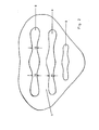
- Fig. 2 eine Ansicht der Pelotte,
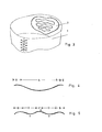
- Fig. 3 eine Ansicht der Rückenstütz-Bsndage mit Pelotte von schräg oben,
- Fig. 4 einen Querschnitt durch die Pelotte im ungespannten Zustand,
- Fig. 5 einen Querschnitt durch die Pelotte im gespannten Zustand,
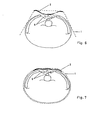
- Fig. 6 einen Querschnitt durch die Rückenstütz- Bandage während des Anlegens vor dem Spannen der Pelotte,
- Fig. 7 einen Querschnitt durch die an den menschlichen Körper angelegte Rückenstütz-Bandage mit gespannter Pelotte.
- Die Rückenstütz-Bandage besteht aus einem um den Körper zu legenden Gurt 1 und der aus einem flachen, federnden Haterial hergestellten Pelotte 2, die in einem Bezug untergebracht ist, der mit einem Klettenverschluß in der Bandage befestigt ist. Die Pelotte 2 ist zusätzlich noch mit einem Polster versehen.
- Wesentliches Teil dieser Rückenstütz-Bandage ist die Pelotte 2, die aus einem Stück federnden Kunststoffes oder aus einem Stück federnden, plattenförmigen Bleches hergestellt ist. Die Pelotte 2 weist im ungespannten Zustand eine Wölbung auf, die dem Rücken des Trägers zugekehrt und damit der Rückenseite (Innenseite) der Bandage abgekehrt ist. Diese Wölbung ist in Fig. 4 in dem Bereich A vorhanden. Die Ränder sind in den Randbereichen B zusätzlich in gleicher Richtung gebogen, um eine breite, flächenhafte Abstützung für den Gurt 1 zu bieten. Wird nun der Gurt am menschlichen Körper gespannt, so wird die Wölbung der Pelotte unter dieser Spannung deformiert. Debei geht diese Wölbung im gespannten Zustand im Querschnitt in eine Wellenlinie über, die aus drei Wölbungen besteht: Einer mittleren Wölbung im Bereich C, die dem Rücken des Trägers abgekehrt ist und zwei seitlich daneben liegenden Wölbungen im Bereich D, die dem Rücken des Trägers zugekehrt sind. Diese drei Wölbungen befinden.sich innerhalb der Randbereiche B, die der Körperseite der Bandage zugekehrtgebogen sind. Durch diese gut aus Fig. 5 und 7 erkennbare Biegung der gewölbten Pelotte ist, wie man besonders gut aus Fig. 7 ersehen kann, der Pelotte eine Form gegeben, bei der die Wölbungen im Bereich D sich auf der Muskulatur neben der Wirbelsäule 6 abstützen. Diese Wölbungen 7 kommen somit beiderseits neben der Wirbelsäule am Rücken des Trägers zur Anlage, während die Wölbung 8 in der Mitte zwischen diesen beiden Wölbungen nach aussen, also vom Rücken des Trägers weg gedrückt ist, so daß auf den Dornfortsätzen der Wirbelsäule selbst keine Abstützung der Pelotte erfolgt.
- Wie aus Fig. 2 ersichtlich ist, weist die Pelotte im wesentlichen an ihrem Umfang eine Herzform auf. Diese Form gewährleistet eine gute Abstützung und ein ungestörtes Tragen der Rückenstütz-Bandage.
- In Fig. 2 sind mehrere Schlitze 9 ersichtlich, die sich in der Pelotte befinden. Diese Schlitze verlaufen quer zur Richtung der Wirbelsäule. Die Schlitze weisen dort, wo sich die seitlichen Wölbungen 7 ausbilden, Verengungen 10 auf, die für die dazwischenliegenden Bereiche 11 breite Flächen erbringen, die sich dann wirkungsvoll auf die Muskelbereiche neben der Wirbelsäule stützen und dadurch die Stützwirkung dieser Rückenstütz-Bandage bewirken.
Claims (10)
daß die Pelotte (2) aus einem flachen, federnden Material besteht, welches im entspannten Zustand gewölbt ist, wobei die Wölbung dem Rücken des Trägers zugekehrt ist und welches im gespannten Zustand im Querschnitt in eine Wellenlinie übergeht, die aus drei Wölbungen (7,8,7) besteht, einer mittleren Wölbun (8), die dem Rücken des Trägers abgekehrt ist und zwei seitlich daneben liegenden Wölbungen (7), die dem Rücken des Trägers zugekehrt sind.
dadurch gekennzeichnet,
daß im Randbereich der Pelotte (2) je eine der Körperseite zugekehrte Biegung vorgesehen ist.
daß der vertikale Querschnitt der Pelotte (2) im mittleren Bereich die anatomische Außenform der Kreuzbeingegend aufweist.
dadurch gekennzeichnet,
daß die Pelotte (2) mindestens zwei quer verlaufende Schlitze (9) aufweist.
dadurch gekennzeichnet,
daß die Schlitze (9) zwei Verengungen (10) im Bereich der beiden äusseren Wölbungen (7) aufweisen.
dadurch gekennzeichnet,
daß der Aussenrand der Pelotte (2) Herzform aufweist.
dadurch gekennzeichnet,
daß die Pelotte (2) aus federndem Kunststoff oder federndem Blech hergestellt ist.
dadurch gekennzeichnet,
daß die Pelotte (2) in einem schweißaufsaugenden Bezug untergebracht ist.
dadurch gekennzeichnet,
daß die Pelotte (2) mit einem Polster versehen ist.
dadurch gekennzeichnet,
daß die Pelotte (2) oder ihr Bezug mit einem Klettenverschluß in der Bandage befestigt ist.
Priority Applications (1)
| Application Number | Priority Date | Filing Date | Title |
|---|---|---|---|
| AT80106123T ATE6985T1 (de) | 1979-10-19 | 1980-10-09 | Rueckenstuetz-bandage. |
Applications Claiming Priority (2)
| Application Number | Priority Date | Filing Date | Title |
|---|---|---|---|
| DE2942295A DE2942295C2 (de) | 1979-10-19 | 1979-10-19 | Rückenstützbandage |
| DE2942295 | 1979-10-19 |
Publications (3)
| Publication Number | Publication Date |
|---|---|
| EP0027602A2 true EP0027602A2 (de) | 1981-04-29 |
| EP0027602A3 EP0027602A3 (en) | 1981-10-28 |
| EP0027602B1 EP0027602B1 (de) | 1984-04-11 |
Family
ID=6083865
Family Applications (1)
| Application Number | Title | Priority Date | Filing Date |
|---|---|---|---|
| EP80106123A Expired EP0027602B1 (de) | 1979-10-19 | 1980-10-09 | Rückenstütz-Bandage |
Country Status (3)
| Country | Link |
|---|---|
| EP (1) | EP0027602B1 (de) |
| AT (1) | ATE6985T1 (de) |
| DE (1) | DE2942295C2 (de) |
Cited By (3)
| Publication number | Priority date | Publication date | Assignee | Title |
|---|---|---|---|---|
| EP0555154A1 (de) * | 1992-02-07 | 1993-08-11 | Charles Lelli | Lendenstützgürtel |
| US20130030337A1 (en) * | 2009-11-25 | 2013-01-31 | Gibaud | Lumbar support belt |
| US20160228279A1 (en) * | 2015-02-10 | 2016-08-11 | Deroyal Industries, Inc. | Adjustable back brace |
Family Cites Families (13)
| Publication number | Priority date | Publication date | Assignee | Title |
|---|---|---|---|---|
| DE120697C (de) * | ||||
| DE7927415U1 (de) * | 1980-01-10 | Witte, Wilhelm, 5830 Schwelm | Lumbalpelotte | |
| US1327930A (en) * | 1917-08-04 | 1920-01-13 | Voorhees Sheldon | Abdominal support |
| US1893960A (en) * | 1931-12-05 | 1933-01-10 | Isaac M Pease | Abdominal supporting belt |
| FR806661A (fr) * | 1936-05-22 | 1936-12-22 | Ceinture anti-ptosique | |
| FR874534A (fr) * | 1941-04-05 | 1942-08-10 | Perfectionnements aux ceintures pour la correction des ptoses de l'estomac, de l'intestin et autres | |
| US2520063A (en) * | 1949-01-06 | 1950-08-22 | Rishcoff Michael | Solid spring frame for solid frame support belts |
| US2541487A (en) * | 1949-12-15 | 1951-02-13 | George H Triplett | Spinal brace |
| FR1104562A (fr) * | 1954-05-14 | 1955-11-22 | Ceinture de maintien orthopédique | |
| DE1541285A1 (de) * | 1966-03-04 | 1969-07-17 | Yardney Entpr Inc | Orthopaedische Stuetzeinrichtung |
| DE2506647C2 (de) * | 1975-02-17 | 1986-02-20 | Tigges, geb.Vogel, Pauline Johanna, 5072 Schildgen | Vorrichtung zur Behandlung des Nervensystems im Wirbelsäulenbereich |
| DE2556757C2 (de) * | 1975-12-17 | 1985-12-05 | John & Bamberg, Orthopädie-Technik im Rehabilitationszentrum Annastift, 3000 Hannover | Rückenstützbandage mit einer Pelotte |
| DE7929633U1 (de) * | 1979-10-19 | 1980-02-28 | Annastift E.V., 3000 Hannover | Rückenstütz-Bandage |
-
1979
- 1979-10-19 DE DE2942295A patent/DE2942295C2/de not_active Expired
-
1980
- 1980-10-09 EP EP80106123A patent/EP0027602B1/de not_active Expired
- 1980-10-09 AT AT80106123T patent/ATE6985T1/de active
Cited By (9)
| Publication number | Priority date | Publication date | Assignee | Title |
|---|---|---|---|---|
| EP0555154A1 (de) * | 1992-02-07 | 1993-08-11 | Charles Lelli | Lendenstützgürtel |
| FR2687062A1 (fr) * | 1992-02-07 | 1993-08-13 | Lelli Charles | Ceinture de maintien lombaire. |
| US5363863A (en) * | 1992-02-07 | 1994-11-15 | Charles Lelli | Lumbar support belt |
| US20130030337A1 (en) * | 2009-11-25 | 2013-01-31 | Gibaud | Lumbar support belt |
| US9283105B2 (en) * | 2009-11-25 | 2016-03-15 | Gibaud | Lumbar support belt |
| US20160228279A1 (en) * | 2015-02-10 | 2016-08-11 | Deroyal Industries, Inc. | Adjustable back brace |
| WO2016130237A1 (en) * | 2015-02-10 | 2016-08-18 | Deroyal Industries, Inc. | Adjustable back brace |
| US10143582B2 (en) * | 2015-02-10 | 2018-12-04 | Deroyal Industries, Inc. | Adjustable back brace |
| US11491040B2 (en) | 2015-02-10 | 2022-11-08 | Deroyal Industries, Inc. | Adjustable back brace |
Also Published As
| Publication number | Publication date |
|---|---|
| EP0027602B1 (de) | 1984-04-11 |
| DE2942295C2 (de) | 1986-06-26 |
| EP0027602A3 (en) | 1981-10-28 |
| DE2942295A1 (de) | 1981-04-30 |
| ATE6985T1 (de) | 1984-04-15 |
Similar Documents
| Publication | Publication Date | Title |
|---|---|---|
| DE2837620C2 (de) | Rückenstützbandage | |
| DE2711170C3 (de) | ||
| DE2751608C2 (de) | Orthopädisches Stützkorsett | |
| DE68903550T2 (de) | Therapeutische vorrichtung fuer das handgelenk. | |
| DE2502202B2 (de) | Stützmieder | |
| CH663150A5 (de) | Zugspanneinrichtung. | |
| DE1030614T1 (de) | Wirbelsäulenimplantat | |
| DE29720475U1 (de) | Minimalorthese zur Behandlung der Osteoporose | |
| DE1197192B (de) | Vorrichtung zum Halten und Berichtigen der Statik der Wirbelsaeule, insbesondere Guertel | |
| EP1688107B1 (de) | Rückenpelotte zur Massage und Stimulation der Rückenmuskulatur, insbesondere im Lumbosakralbereich | |
| DE19808228B4 (de) | Kreuzstützbandage | |
| EP0027602B1 (de) | Rückenstütz-Bandage | |
| DE2506647A1 (de) | Vorrichtung zur behandlung des nervensystems im wirbelsaeulenbereich | |
| DE2334500A1 (de) | Vorrichtung zur stuetzung und korrektur der menschlichen wirbelsaeule | |
| DE2454702C2 (de) | Vorrichtung zur Behandlung des Nervensystems im Wirbelsäulenbereich | |
| DE102009029804B4 (de) | Stützeinrichtung | |
| DE102017108840B4 (de) | Stützkörper mit Massagewirkung und Bandage | |
| DE7929633U1 (de) | Rückenstütz-Bandage | |
| DE578241C (de) | Vorrichtung zur Stuetzung des Kreuz- und Darmbeins sowie der Lendenwirbelsaeule | |
| DE1816588B2 (de) | Vorrichtung zur Stuetze und Korrektur der menschlichen Wirbelsaeule | |
| DE2743996A1 (de) | Vorrichtung zur skoliosetherapie | |
| DE1566401C3 (de) | Vorrichtung zur Stützung und Korrektur der menschlichen Wirbelsäule | |
| DE3049097A1 (de) | Kreuzbeinpelotte | |
| DE699811C (de) | Elastischer Knieschuetzer | |
| AT378477B (de) | Skoliosemieder |
Legal Events
| Date | Code | Title | Description |
|---|---|---|---|
| PUAI | Public reference made under article 153(3) epc to a published international application that has entered the european phase |
Free format text: ORIGINAL CODE: 0009012 |
|
| AK | Designated contracting states |
Designated state(s): AT BE CH FR GB LU NL SE |
|
| PUAL | Search report despatched |
Free format text: ORIGINAL CODE: 0009013 |
|
| AK | Designated contracting states |
Designated state(s): AT BE CH FR GB LU NL SE |
|
| 17P | Request for examination filed |
Effective date: 19811229 |
|
| GRAA | (expected) grant |
Free format text: ORIGINAL CODE: 0009210 |
|
| AK | Designated contracting states |
Designated state(s): AT BE CH FR GB LI LU NL SE |
|
| REF | Corresponds to: |
Ref document number: 6985 Country of ref document: AT Date of ref document: 19840415 Kind code of ref document: T |
|
| ET | Fr: translation filed | ||
| PG25 | Lapsed in a contracting state [announced via postgrant information from national office to epo] |
Ref country code: LU Free format text: LAPSE BECAUSE OF NON-PAYMENT OF DUE FEES Effective date: 19841031 |
|
| PLBE | No opposition filed within time limit |
Free format text: ORIGINAL CODE: 0009261 |
|
| STAA | Information on the status of an ep patent application or granted ep patent |
Free format text: STATUS: NO OPPOSITION FILED WITHIN TIME LIMIT |
|
| 26N | No opposition filed | ||
| PGFP | Annual fee paid to national office [announced via postgrant information from national office to epo] |
Ref country code: GB Payment date: 19931008 Year of fee payment: 14 |
|
| PG25 | Lapsed in a contracting state [announced via postgrant information from national office to epo] |
Ref country code: GB Effective date: 19941009 |
|
| EAL | Se: european patent in force in sweden |
Ref document number: 80106123.5 |
|
| GBPC | Gb: european patent ceased through non-payment of renewal fee |
Effective date: 19941009 |
|
| PGFP | Annual fee paid to national office [announced via postgrant information from national office to epo] |
Ref country code: SE Payment date: 19991029 Year of fee payment: 20 Ref country code: NL Payment date: 19991029 Year of fee payment: 20 |
|
| PGFP | Annual fee paid to national office [announced via postgrant information from national office to epo] |
Ref country code: AT Payment date: 19991031 Year of fee payment: 20 |
|
| PGFP | Annual fee paid to national office [announced via postgrant information from national office to epo] |
Ref country code: FR Payment date: 19991102 Year of fee payment: 20 |
|
| PGFP | Annual fee paid to national office [announced via postgrant information from national office to epo] |
Ref country code: BE Payment date: 19991103 Year of fee payment: 20 |
|
| PGFP | Annual fee paid to national office [announced via postgrant information from national office to epo] |
Ref country code: CH Payment date: 19991130 Year of fee payment: 20 |
|
| BE20 | Be: patent expired |
Free format text: 20001009 *ANNASTIFT E.V. FORSCHUNGSLABOR |
|
| PG25 | Lapsed in a contracting state [announced via postgrant information from national office to epo] |
Ref country code: LI Free format text: LAPSE BECAUSE OF EXPIRATION OF PROTECTION Effective date: 20001008 Ref country code: CH Free format text: LAPSE BECAUSE OF EXPIRATION OF PROTECTION Effective date: 20001008 |
|
| PG25 | Lapsed in a contracting state [announced via postgrant information from national office to epo] |
Ref country code: NL Free format text: LAPSE BECAUSE OF EXPIRATION OF PROTECTION Effective date: 20001009 Ref country code: AT Free format text: LAPSE BECAUSE OF EXPIRATION OF PROTECTION Effective date: 20001009 |
|
| PG25 | Lapsed in a contracting state [announced via postgrant information from national office to epo] |
Ref country code: SE Free format text: THE PATENT HAS BEEN ANNULLED BY A DECISION OF A NATIONAL AUTHORITY Effective date: 20001030 |
|
| REG | Reference to a national code |
Ref country code: CH Ref legal event code: PL |
|
| NLV7 | Nl: ceased due to reaching the maximum lifetime of a patent |
Effective date: 20001009 |
|
| EUG | Se: european patent has lapsed |
Ref document number: 80106123.5 |