EP0028068A1 - Dispositif de commande séquentielle pour une machine-outil et procédé pour préparer et exécuter un programme séquentiel pour dispositif de commande servant à la commande de machine-outil - Google Patents
Dispositif de commande séquentielle pour une machine-outil et procédé pour préparer et exécuter un programme séquentiel pour dispositif de commande servant à la commande de machine-outil Download PDFInfo
- Publication number
- EP0028068A1 EP0028068A1 EP80303261A EP80303261A EP0028068A1 EP 0028068 A1 EP0028068 A1 EP 0028068A1 EP 80303261 A EP80303261 A EP 80303261A EP 80303261 A EP80303261 A EP 80303261A EP 0028068 A1 EP0028068 A1 EP 0028068A1
- Authority
- EP
- European Patent Office
- Prior art keywords
- sequence
- subroutine
- program
- control
- command
- Prior art date
- Legal status (The legal status is an assumption and is not a legal conclusion. Google has not performed a legal analysis and makes no representation as to the accuracy of the status listed.)
- Ceased
Links
Images


Classifications
-
- G—PHYSICS
- G05—CONTROLLING; REGULATING
- G05B—CONTROL OR REGULATING SYSTEMS IN GENERAL; FUNCTIONAL ELEMENTS OF SUCH SYSTEMS; MONITORING OR TESTING ARRANGEMENTS FOR SUCH SYSTEMS OR ELEMENTS
- G05B19/00—Program-control systems
- G05B19/02—Program-control systems electric
- G05B19/04—Program control other than numerical control, i.e. in sequence controllers or logic controllers
- G05B19/05—Programmable logic controllers, e.g. simulating logic interconnections of signals according to ladder diagrams or function charts
- G05B19/056—Programming the PLC
-
- G—PHYSICS
- G05—CONTROLLING; REGULATING
- G05B—CONTROL OR REGULATING SYSTEMS IN GENERAL; FUNCTIONAL ELEMENTS OF SUCH SYSTEMS; MONITORING OR TESTING ARRANGEMENTS FOR SUCH SYSTEMS OR ELEMENTS
- G05B2219/00—Program-control systems
- G05B2219/10—Plc systems
- G05B2219/13—Plc programming
- G05B2219/13005—Subroutine
-
- G—PHYSICS
- G05—CONTROLLING; REGULATING
- G05B—CONTROL OR REGULATING SYSTEMS IN GENERAL; FUNCTIONAL ELEMENTS OF SUCH SYSTEMS; MONITORING OR TESTING ARRANGEMENTS FOR SUCH SYSTEMS OR ELEMENTS
- G05B2219/00—Program-control systems
- G05B2219/10—Plc systems
- G05B2219/13—Plc programming
- G05B2219/13008—Quicker execution of jumps when repeating same kind of operation
-
- G—PHYSICS
- G05—CONTROLLING; REGULATING
- G05B—CONTROL OR REGULATING SYSTEMS IN GENERAL; FUNCTIONAL ELEMENTS OF SUCH SYSTEMS; MONITORING OR TESTING ARRANGEMENTS FOR SUCH SYSTEMS OR ELEMENTS
- G05B2219/00—Program-control systems
- G05B2219/10—Plc systems
- G05B2219/13—Plc programming
- G05B2219/13093—Using functions like arithmetic timers in program
-
- Y—GENERAL TAGGING OF NEW TECHNOLOGICAL DEVELOPMENTS; GENERAL TAGGING OF CROSS-SECTIONAL TECHNOLOGIES SPANNING OVER SEVERAL SECTIONS OF THE IPC; TECHNICAL SUBJECTS COVERED BY FORMER USPC CROSS-REFERENCE ART COLLECTIONS [XRACs] AND DIGESTS
- Y10—TECHNICAL SUBJECTS COVERED BY FORMER USPC
- Y10T—TECHNICAL SUBJECTS COVERED BY FORMER US CLASSIFICATION
- Y10T483/00—Tool changing
- Y10T483/10—Process
-
- Y—GENERAL TAGGING OF NEW TECHNOLOGICAL DEVELOPMENTS; GENERAL TAGGING OF CROSS-SECTIONAL TECHNOLOGIES SPANNING OVER SEVERAL SECTIONS OF THE IPC; TECHNICAL SUBJECTS COVERED BY FORMER USPC CROSS-REFERENCE ART COLLECTIONS [XRACs] AND DIGESTS
- Y10—TECHNICAL SUBJECTS COVERED BY FORMER USPC
- Y10T—TECHNICAL SUBJECTS COVERED BY FORMER US CLASSIFICATION
- Y10T483/00—Tool changing
- Y10T483/12—Tool changing with means to regulate operation by means of replaceable information supply [e.g., templet, tape, card, etc. ]
- Y10T483/123—Replaceable information comprising tool location
Definitions
- This invention relates to a method of preparing and executing a sequence program for a programmable sequence controller for such applications as machine tool control.
- Sequence control executed by a sequence controller ranks along with feedback control as one of the two principal forms of automatic control, and it has recently found use in controlling a variety of industrial machines.
- sequence control a sequence program utilizing a prepared subroutine is written in accordance with the operating sequence of the machine which is to be controlled, and the program is loaded into the memory of a programmable sequence controller.
- the sequence can be expressed in terms of relay symbols, logical symbols or by Boolean algebra.
- the relay symbol method of representing the sequence is advantageous if consideration is given to the historical background of the old sequence controllers constructed by combining contact relays.
- the relay symbol system necessitates an extremely complicated process when applied to a machine tool of the type having an automatic tool changing mechanism.
- a machine tool of this type a magazine is revolved to permit a desired tool to be extracted from a tool holder and then attached to a spindle head, or to permit a tool which is already mounted in a spindle to be extracted from the spindle and carried back to the original position where the tool is again accommodated.in the tool holder.
- a complicated process of this type generally cannot be expressed in the form of a ladder diagram and must be programmed separately by means of assembly language or the like. Hence there is need for a method which can facilitate the writing of a sequence program for exdcuting a complicated process.
- the present invention discloses/a method of preparing and executing a sequence program for a sequence controller used to control a machine tool, through which a simplification is achieved in the writing of a sequence program for executing, by means of a subroutine, a complicated machine tool sequence.
- the present invention can provide a method of preparing and a method of executing a sequence program for a sequence controller used to control a machine tool, through which the writing of the sequence program can be facilitated.
- the present invention can provide a method of preparing and a method of executing a sequence program for a sequence controller used to control a machine tool, through which a simplification is achieved in the writing a program for a complicated sequence.
- the present invention can provide a method of preparing and a method of executing a sequence program for a sequence controller used to control a machine tool, through which even an individual who is not proficient in the preparation of sequences can readily write a sequence program.
- the present invention can provide a method of preparing and a method of executing a sequence program for a sequence controller used to control a machine tool, through which a sequence program can be written easily using a sequence diagram in which a function command is expressed by being divided into a control condition command and parameters.
- a table 1 for supporting a workpiece is adapted to the moved in X-, Y- and Z-directions on a base 2.
- a spindle head 3 is provided for mounting a tool, as well as a magazine 5, which is movable vertically along a main column 4, for rotatively carrying a plurality of tools 6.
- the magazine has a holding member 7 for holding the arbor of a corresponding tool 6.
- To change tools the magazine 5 is revolved to bring a prescribed one of the tools 6 into position directly above the spindle head 3, after which the magazine 5 is lowered to bring the corresponding arbor into position in front of the spindle head.
- the spindle .head 3 whose rotary shaft has a chuck provided at the end thereof, is then projected forwardly so that the arbor of the selected tool is received and then grasped by the chuck. Next, when the magazine is raised, the tool separates from the corresponding holding member 7 and is left mounted on the spindle head 3.
- the magazine 5 of the machining center depicted in Fig. 1 is divided into 12 quadrants as illustrated in Figs. 2A and 2B, each quadrant being equipped with a single tool.
- the magazine 5 is capable of being rotated in the clockwise (CW) direction only, or in both the clockwise and counter-clockwise (CCW) directions.
- CW clockwise
- CCW counter-clockwise
- the sequence for control of magazine rotation can be expressed in the form of a ladder diagram.
- the function command for the control of rotation is expressed by dividing it into control condition data, and data consisting of parameters for a subroutine.
- the conditions which need to be set for controlling the rotation of the magazine 5 are four in number. They are: (1) whether the number represetning the position of the magazine'starts from 0 or 1; (2) whether the direction of magazine rotation is the CW direction only or both the CW and CCW directions; (3) whether the number of steps from the present position of the magazine to a target position is to be computed, or from the present position to that position one step before the target position because of a braking operation; and (4) whether the rotation control sequence is to be executed or not. All of these conditions can be expressed by a relay code having a symbolic code attached thereto. These conditions for controlling the rotation of the magazine are expressed in Fig. 3.
- the parameters for the subroutine are the number of steps by which the magazine 5 is to be rotationally indexed, the address of the present position of the magazine (which is at position No. 7 in the example of Fig. 2), the address of the target position, and the address which identifies the result of a computation. These values are expressed in the form of a two-digit BCD.
- Fig. 4 is a ladder diagram expressing the sequence of the rotation control function described above, and which is used to prepare a sequence program for rotation control.
- the relay code is the portion which sets the control conditions, and each control condition is expressed by a symbolic code.
- Shown in Fig. 4 are the addresses identifying the locations of the memory where the data, representing the control conditions, is stored. According to the notation employed to express these addresses, the first bit at the 10th address of the memory shall be expressed by "10.1", and so on.
- data to be processed by the subroutine is expressed directly in the form of a BCD.
- a symbol Rl with 20.1 is employed to write the result of the execution by the subroutine in the first bit of 20th address.
- a ladder diagram of the foregoing type is used to pre- .pare a sequence program, of the type shown in Fig. 5, for a rotation control command. This program is written in the memory which is used to store the sequence program.
- the direction of rotation obtained by executing the subroutine pro- "gram is written in the first bit at the 20th address of the memory.
- the direction of rotation is CW if the result is "0", and CCW when the result is "1".
- M function command signal is composed of an M code signal of one digit indicative of an M function command, and an BCD code of eight digits.
- the M function command signal delivered by the numerical control device is temporarily stored in the memory of the sequence controller.
- the M code signal of the M function command signal is stored in, say, the Oth bit at the 66th address, as shown in Fig. 6, and the BCD code of 8 digits is stored in order from the Oth bit to the 7th bit at the 67th dddress.
- a sequence for decoding the M function command from the numerical control device on the sequence controller side can be expressed using a ladder circuit that employs 9 relay contacts, as illustrated in Fig. 7.
- Ten steps are required in the logical operation for decoding the function command, and the process is fairly complex.
- a great reduction in the number of steps can be achieved if the decoding operation on the side of the sequence controller is processed by a method relying upon the abovesaid subroutine.
- a ladder diagram shown in Fig. 8 uses a relay code to express a sequence for a case where the M function command is to be decoded at the sequence controller.
- Fig. 8 uses a relay code to express a sequence for a case where the M function command is to be decoded at the sequence controller.
- a relay contact ACT is the portion for setting the control condition, and it designates the address (specifically the Oth bit of the 66th address), of the memory, at which the M code signal is stored. 1tthe M code signal is a "1", the decoding operation takes place; if a "0", no decoding takes place, i.e., relay M 40 is in the OFF position.
- the portion which represents the data sent to the subroutine comprises a portion A representing the symbolic code DEC of a decode command, an address assigning portion B for assigining the address (the 67th address) of the memory at which the BCD code of the M function command is stored, and a decode designating portion C.
- written in the address assigning portion B in the form of a two-digit BCD is the address of the location which stores the BCD code of the M function signal sent by the numerical control device, and written in the decode designating portion C is a decode number as well as a value which is indicative of the number of digits to be decoded.
- the decode number will be 40, for example, if M40 is to be decoded. If the value indicative of the number of digits to be decoded is 01, this means that decoding is conducted with the higher order digit of the two-digit BCD of M function signal (a two-digit number in decimal notation) set to zero; if 10, decoding is conducted with the lower order digit; if 11, both digits are decoded.
- a sequence program for a decode command is prepared on the basis of the ladder diagram of Fig. 8.
- the program is written in the memory which stores the sequence program.
- M function signal "M40" is instructed from the numerical controller, logical value "1" is set in the 5th bit of the 20th address of the memory. Then the content of the said bit is read out and sent to the machine tool side resulting ih the action of the machine tool corresponding to the "M40".
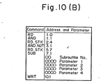
- a timer process command expressed by TMR a counter command denoted by CTR, a code conversion command denoted by COD, a data transfer command, following a logical multiplication, denoted by MOVE, a common lime control command denoted by COM, a jump command denoted by JMP, a parity check command denoted by PARI, a non-volatile memory write command denoted by MWRT, a binary to BCD or BCD to binary data conversion command denoted by DCNV, a magnitude comparison command denoted by COMP, a coincidence decision command denoted by COIM, and the like are expressed by the ladder diagram and programmed.
- the subroutine In executing these function commands, the subroutine is informed of the control conditions after they are stored in a register through the use of the RD and RD ⁇ STK commands and the like, and the subroutine is informed of the parameters by defining them in the sequence program. Since each of the control conditions of which the subroutine is notified is the result (1,0) of a logical operation, it may be expressed as the result of a logical operation using AND, OR combiantions.
- a sequence controller for a machine tool has its sequence prepared by dividing a function command into control conditions and parameter which are expressed by a sequence diagram.
- the processing is carried out by the subroutine of each command. Therefore, in connection with sequence preparation, the present invention makes it possible to express, by means of a sequence diagram, fucntion commands of the type which could not be expressed by a sequence diagram with the conventional methods. It is also possible to express simply even fairly complex sequence diagrams. As a result, even individuals who are not highly skilled in sequence preparation can easily prepare a sequence for a machine tool.
- a method of preparing and executing a sequence program for effecting the sequence control of a sequence controller for a machine tool by executing a subroutine program A sequence diagram is prepared, which diagram expresses a function command for a subroutine as data divided into control conditions and parameters. From the sequence diagram a sequence program is prepared, which program includes a command for reading data indicative of a control condition, and parameter data of which a subroutine is informed. The sequence program so prepared is then executed
Landscapes
- Physics & Mathematics (AREA)
- General Physics & Mathematics (AREA)
- Engineering & Computer Science (AREA)
- Automation & Control Theory (AREA)
- Programmable Controllers (AREA)
Applications Claiming Priority (2)
| Application Number | Priority Date | Filing Date | Title |
|---|---|---|---|
| JP11962779A JPS5642805A (en) | 1979-09-18 | 1979-09-18 | Sequence producing system for sequence controller controlling machine tool |
| JP119627/79 | 1979-09-18 |
Publications (1)
| Publication Number | Publication Date |
|---|---|
| EP0028068A1 true EP0028068A1 (fr) | 1981-05-06 |
Family
ID=14766116
Family Applications (1)
| Application Number | Title | Priority Date | Filing Date |
|---|---|---|---|
| EP80303261A Ceased EP0028068A1 (fr) | 1979-09-18 | 1980-09-17 | Dispositif de commande séquentielle pour une machine-outil et procédé pour préparer et exécuter un programme séquentiel pour dispositif de commande servant à la commande de machine-outil |
Country Status (3)
| Country | Link |
|---|---|
| US (1) | US4396974A (fr) |
| EP (1) | EP0028068A1 (fr) |
| JP (1) | JPS5642805A (fr) |
Cited By (5)
| Publication number | Priority date | Publication date | Assignee | Title |
|---|---|---|---|---|
| EP0097444A3 (fr) * | 1982-06-05 | 1984-08-01 | Fanuc Ltd. | Méthode de visualisation d'un diagramme en échelles |
| EP0067446B1 (fr) * | 1981-06-17 | 1988-11-02 | Hitachi, Ltd. | Dispositif de traitement de données de commande pour robot |
| EP0190358A4 (fr) * | 1984-07-27 | 1989-03-29 | Fanuc Ltd | Systeme de gestion d'un controleur programmable. |
| EP0586813A3 (en) * | 1992-09-09 | 1996-05-08 | Allen Bradley Co | Programmable controller with ladder diagram macro instructions |
| EP0827053A4 (fr) * | 1996-03-18 | 1998-08-05 | Fanuc Ltd | Systeme de programmation pour controleur de deplacement |
Families Citing this family (27)
| Publication number | Priority date | Publication date | Assignee | Title |
|---|---|---|---|---|
| EP0074412B1 (fr) * | 1981-03-23 | 1990-07-11 | Fanuc Ltd. | Systeme de commande numerique |
| US4525041A (en) * | 1982-02-24 | 1985-06-25 | Precision Grinding Limited | Arrangement for use in positioning an optical image |
| JPS605302A (ja) * | 1983-06-24 | 1985-01-11 | Mitsubishi Electric Corp | シ−ケンスコントロ−ラのプログラム方法 |
| JPS60201806A (ja) * | 1984-03-24 | 1985-10-12 | Hitachi Seiki Co Ltd | ワ−ク及びチヤツク爪自動交換用ロボツト付νc旋盤 |
| JPS61168004A (ja) * | 1985-01-21 | 1986-07-29 | Mitsubishi Electric Corp | 応用命令を備えたプログラマブル・コントロ−ラ |
| JPS6235906A (ja) * | 1985-08-09 | 1987-02-16 | Fanuc Ltd | シ−ケンス制御方法 |
| JPS62130406A (ja) * | 1985-11-30 | 1987-06-12 | Fanuc Ltd | Ncデ−タ出力方法 |
| JPS63113703A (ja) * | 1986-10-31 | 1988-05-18 | Mitsubishi Electric Corp | シ−ケンスコントロ−ラ用ラダ−線図入力方法 |
| JPS63273101A (ja) * | 1987-04-30 | 1988-11-10 | Fanuc Ltd | プログラマブル・コントロ−ラ |
| JPS6462706A (en) * | 1987-09-03 | 1989-03-09 | Fanuc Ltd | Nc program output system |
| JP2522040B2 (ja) * | 1989-04-19 | 1996-08-07 | 三菱電機株式会社 | 位置決め機能付きプログラムコントロ―ラのプログラム入力方法 |
| JP2533372B2 (ja) * | 1989-05-19 | 1996-09-11 | 本田技研工業株式会社 | 制御プログラム作成方法 |
| US5127099A (en) * | 1989-06-30 | 1992-06-30 | Icom, Inc. | Method and apparatus for securing access to a ladder logic programming and monitoring system |
| US5349518A (en) * | 1989-06-30 | 1994-09-20 | Icom, Inc. | Method and apparatus for symbolic ladder logic programming with automatic attachment of addresses |
| US5276811A (en) * | 1989-06-30 | 1994-01-04 | Icom, Inc. | Method for emulating programmable logic controller by exchanging information between debug program which emulates I/O devices and ladder logic program |
| US4991076A (en) * | 1989-06-30 | 1991-02-05 | Icom Inc. | Method and apparatus for creating custom displays for monitoring ladder logic programs |
| US5267145A (en) * | 1989-06-30 | 1993-11-30 | Icom, Inc. | Method and apparatus for program navigation and editing for ladder logic programs by determining which instructions reference a selected data element address |
| US5243511A (en) * | 1989-06-30 | 1993-09-07 | Icom, Inc. | Method and apparatus for block move re-addressing in ladder logic programs |
| US5321829A (en) * | 1990-07-20 | 1994-06-14 | Icom, Inc. | Graphical interfaces for monitoring ladder logic programs |
| JP2660603B2 (ja) * | 1990-07-23 | 1997-10-08 | 三菱電機株式会社 | 制御プログラムのパラメータ設定方法 |
| US7069185B1 (en) * | 1999-08-30 | 2006-06-27 | Wilson Diagnostic Systems, Llc | Computerized machine controller diagnostic system |
| US7003733B2 (en) * | 2001-01-30 | 2006-02-21 | Duemler David W | Programmable logic controller programming system |
| JP2004341695A (ja) * | 2003-05-14 | 2004-12-02 | Konica Minolta Photo Imaging Inc | 表示システム |
| JP2007328692A (ja) * | 2006-06-09 | 2007-12-20 | Canon Inc | 代数演算方法及びその装置、プログラム |
| JP6577128B2 (ja) * | 2015-03-27 | 2019-09-18 | ビューラー アーゲー | 適応可能なクロスプラント制御および操作システム、およびその対応する方法 |
| JP6247265B2 (ja) * | 2015-09-29 | 2017-12-13 | ファナック株式会社 | 工具交換装置 |
| JP6400558B2 (ja) * | 2015-11-17 | 2018-10-03 | ファナック株式会社 | シーケンス制御プログラミング装置、シーケンス制御プログラミング方法及び作業システム |
Citations (1)
| Publication number | Priority date | Publication date | Assignee | Title |
|---|---|---|---|---|
| US4038533A (en) * | 1976-09-29 | 1977-07-26 | Allen-Bradley Company | Industrial control processor system |
Family Cites Families (7)
| Publication number | Priority date | Publication date | Assignee | Title |
|---|---|---|---|---|
| US4096563A (en) * | 1973-12-03 | 1978-06-20 | Houdaille Industries, Inc. | Machine tool control system and method |
| IT1009329B (it) * | 1974-03-18 | 1976-12-10 | Mst Spa | Perfezionamento nei sistemi di con trollo per macchinario ed impianti in generale particolarmente de scritto per applicazioni su macchi ne utensili |
| US3987282A (en) * | 1975-04-22 | 1976-10-19 | Redactron Corporation | Shaft position controlling system |
| JPS51130781A (en) * | 1975-05-09 | 1976-11-13 | Toyoda Mach Works Ltd | Group controlling system |
| JPS51148339A (en) * | 1975-06-16 | 1976-12-20 | Toshiba Corp | Computer control unit |
| US4152765A (en) * | 1977-09-15 | 1979-05-01 | Weber John M | Programmer unit for N/C systems |
| US4281379A (en) * | 1978-12-18 | 1981-07-28 | Mcdonnell Douglas Corporation | Computer driven control system for a numerically controlled machine tool |
-
1979
- 1979-09-18 JP JP11962779A patent/JPS5642805A/ja active Pending
-
1980
- 1980-09-10 US US06/185,808 patent/US4396974A/en not_active Expired - Lifetime
- 1980-09-17 EP EP80303261A patent/EP0028068A1/fr not_active Ceased
Patent Citations (1)
| Publication number | Priority date | Publication date | Assignee | Title |
|---|---|---|---|---|
| US4038533A (en) * | 1976-09-29 | 1977-07-26 | Allen-Bradley Company | Industrial control processor system |
Non-Patent Citations (1)
| Title |
|---|
| LE NOVEL AUTOMATISME, Vol. 23, 1978, October-November, No. 9/10, Paris FR, D. MANSION: "Des systemes de commande industrielle combinant des automates et des calculateurs", pages 277-283 * |
Cited By (5)
| Publication number | Priority date | Publication date | Assignee | Title |
|---|---|---|---|---|
| EP0067446B1 (fr) * | 1981-06-17 | 1988-11-02 | Hitachi, Ltd. | Dispositif de traitement de données de commande pour robot |
| EP0097444A3 (fr) * | 1982-06-05 | 1984-08-01 | Fanuc Ltd. | Méthode de visualisation d'un diagramme en échelles |
| EP0190358A4 (fr) * | 1984-07-27 | 1989-03-29 | Fanuc Ltd | Systeme de gestion d'un controleur programmable. |
| EP0586813A3 (en) * | 1992-09-09 | 1996-05-08 | Allen Bradley Co | Programmable controller with ladder diagram macro instructions |
| EP0827053A4 (fr) * | 1996-03-18 | 1998-08-05 | Fanuc Ltd | Systeme de programmation pour controleur de deplacement |
Also Published As
| Publication number | Publication date |
|---|---|
| JPS5642805A (en) | 1981-04-21 |
| US4396974A (en) | 1983-08-02 |
Similar Documents
| Publication | Publication Date | Title |
|---|---|---|
| EP0028068A1 (fr) | Dispositif de commande séquentielle pour une machine-outil et procédé pour préparer et exécuter un programme séquentiel pour dispositif de commande servant à la commande de machine-outil | |
| JPS58175003A (ja) | 数値制御指令方式 | |
| EP0312608B1 (fr) | Dispositif de commande numerique | |
| US4109188A (en) | Index device for tool storage magazine | |
| JPH0463652A (ja) | Nc加工制御装置 | |
| US4692872A (en) | Numerical control system with plural groups of miscellaneous functions | |
| WO1985003470A1 (fr) | Systeme d'affichage d'outils pour un echangeur automatique d'outils | |
| JPH01308185A (ja) | モータ制御装置 | |
| WO1992001522A1 (fr) | Procede de selection d'outil pour presse a poinçonner | |
| EP0074412B1 (fr) | Systeme de commande numerique | |
| EP4006664B1 (fr) | Dispositif de réglage d'informations d'outil et machine-outil | |
| EP0078326B1 (fr) | Systeme de commande numerique | |
| WO1990001735A1 (fr) | Systeme d'affichage de donnees d'usinage | |
| JPH02172646A (ja) | 数値制御装置 | |
| KR830002779B1 (ko) | 공작기계의 시이퀀스 제어기의 시이퀀스 프로그램 작성방법 | |
| JPS6333168B2 (fr) | ||
| JPS58211842A (ja) | 工具取替装置を備えた数値制御工作機械 | |
| JPS6089202A (ja) | 数値制御方式 | |
| JP4494303B2 (ja) | 数値制御装置 | |
| EP0180647A1 (fr) | Systeme d'instructions de fonction pour un controleur programmable | |
| JPS62152635A (ja) | 数値制御工作機械の工具番号メモリによる工具選出方法 | |
| JP3060515B2 (ja) | 生産量管理装置 | |
| JPS5857904A (ja) | 多軸かんな盤の制御装置 | |
| JPH0839393A (ja) | 数値制御装置 | |
| JPS6232802B2 (fr) |
Legal Events
| Date | Code | Title | Description |
|---|---|---|---|
| PUAI | Public reference made under article 153(3) epc to a published international application that has entered the european phase |
Free format text: ORIGINAL CODE: 0009012 |
|
| AK | Designated contracting states |
Designated state(s): AT BE CH DE FR GB IT LI LU NL SE |
|
| 17P | Request for examination filed |
Effective date: 19811015 |
|
| RAP1 | Party data changed (applicant data changed or rights of an application transferred) |
Owner name: FANUC LIMITED |
|
| RAP1 | Party data changed (applicant data changed or rights of an application transferred) |
Owner name: FANUC LTD |
|
| RBV | Designated contracting states (corrected) |
Designated state(s): DE FR GB NL |
|
| STAA | Information on the status of an ep patent application or granted ep patent |
Free format text: STATUS: THE APPLICATION HAS BEEN REFUSED |
|
| 18R | Application refused |
Effective date: 19890220 |
|
| APAF | Appeal reference modified |
Free format text: ORIGINAL CODE: EPIDOSCREFNE |
|
| RIN1 | Information on inventor provided before grant (corrected) |
Inventor name: NAKAJIMA, YOSHIHIRO Inventor name: IMAZEKI, RYOJI Inventor name: KUSUMI, KATSUAKI |