EP0028358A2 - Procédé et appareil pour fabriquer des éléments de fermetures à glissières - Google Patents
Procédé et appareil pour fabriquer des éléments de fermetures à glissières Download PDFInfo
- Publication number
- EP0028358A2 EP0028358A2 EP80106442A EP80106442A EP0028358A2 EP 0028358 A2 EP0028358 A2 EP 0028358A2 EP 80106442 A EP80106442 A EP 80106442A EP 80106442 A EP80106442 A EP 80106442A EP 0028358 A2 EP0028358 A2 EP 0028358A2
- Authority
- EP
- European Patent Office
- Prior art keywords
- legs
- teeth
- coupling elements
- slide fastener
- blank rod
- Prior art date
- Legal status (The legal status is an assumption and is not a legal conclusion. Google has not performed a legal analysis and makes no representation as to the accuracy of the status listed.)
- Granted
Links
Images



Classifications
-
- A—HUMAN NECESSITIES
- A44—HABERDASHERY; JEWELLERY
- A44B—BUTTONS, PINS, BUCKLES, SLIDE FASTENERS, OR THE LIKE
- A44B19/00—Slide fasteners
- A44B19/42—Making by processes not fully provided for in one other class, e.g. B21D53/50, B21F45/18, B22D17/16, B29D5/00
- A44B19/44—Securing metal interlocking members to ready-made stringer tapes
- A44B19/46—Securing separate interlocking members
-
- B—PERFORMING OPERATIONS; TRANSPORTING
- B21—MECHANICAL METAL-WORKING WITHOUT ESSENTIALLY REMOVING MATERIAL; PUNCHING METAL
- B21D—WORKING OR PROCESSING OF SHEET METAL OR METAL TUBES, RODS OR PROFILES WITHOUT ESSENTIALLY REMOVING MATERIAL; PUNCHING METAL
- B21D53/00—Making other particular articles
- B21D53/46—Making other particular articles haberdashery, e.g. buckles, combs; pronged fasteners, e.g. staples
- B21D53/50—Making other particular articles haberdashery, e.g. buckles, combs; pronged fasteners, e.g. staples metal slide-fastener parts
- B21D53/52—Making other particular articles haberdashery, e.g. buckles, combs; pronged fasteners, e.g. staples metal slide-fastener parts fastener elements; Attaching such elements so far as this procedure is combined with the process for making the elements
-
- B—PERFORMING OPERATIONS; TRANSPORTING
- B21—MECHANICAL METAL-WORKING WITHOUT ESSENTIALLY REMOVING MATERIAL; PUNCHING METAL
- B21J—FORGING; HAMMERING; PRESSING METAL; RIVETING; FORGE FURNACES
- B21J5/00—Methods for forging, hammering, or pressing; Special equipment or accessories therefor
- B21J5/06—Methods for forging, hammering, or pressing; Special equipment or accessories therefor for performing particular operations
- B21J5/12—Forming profiles on internal or external surfaces
-
- B—PERFORMING OPERATIONS; TRANSPORTING
- B21—MECHANICAL METAL-WORKING WITHOUT ESSENTIALLY REMOVING MATERIAL; PUNCHING METAL
- B21K—MAKING FORGED OR PRESSED METAL PRODUCTS, e.g. HORSE-SHOES, RIVETS, BOLTS OR WHEELS
- B21K23/00—Making other articles
-
- A—HUMAN NECESSITIES
- A44—HABERDASHERY; JEWELLERY
- A44B—BUTTONS, PINS, BUCKLES, SLIDE FASTENERS, OR THE LIKE
- A44B19/00—Slide fasteners
- A44B19/02—Slide fasteners with a series of separate interlocking members secured to each stringer tape
- A44B19/04—Stringers arranged edge-to-edge when fastened, e.g. abutting stringers
- A44B19/06—Stringers arranged edge-to-edge when fastened, e.g. abutting stringers with substantially rectangular members having interlocking projections and pieces
-
- Y—GENERAL TAGGING OF NEW TECHNOLOGICAL DEVELOPMENTS; GENERAL TAGGING OF CROSS-SECTIONAL TECHNOLOGIES SPANNING OVER SEVERAL SECTIONS OF THE IPC; TECHNICAL SUBJECTS COVERED BY FORMER USPC CROSS-REFERENCE ART COLLECTIONS [XRACs] AND DIGESTS
- Y10—TECHNICAL SUBJECTS COVERED BY FORMER USPC
- Y10T—TECHNICAL SUBJECTS COVERED BY FORMER US CLASSIFICATION
- Y10T29/00—Metal working
- Y10T29/49—Method of mechanical manufacture
- Y10T29/49782—Method of mechanical manufacture of a slide fastener
- Y10T29/49785—Method of mechanical manufacture of a slide fastener of interlocking element
-
- Y—GENERAL TAGGING OF NEW TECHNOLOGICAL DEVELOPMENTS; GENERAL TAGGING OF CROSS-SECTIONAL TECHNOLOGIES SPANNING OVER SEVERAL SECTIONS OF THE IPC; TECHNICAL SUBJECTS COVERED BY FORMER USPC CROSS-REFERENCE ART COLLECTIONS [XRACs] AND DIGESTS
- Y10—TECHNICAL SUBJECTS COVERED BY FORMER USPC
- Y10T—TECHNICAL SUBJECTS COVERED BY FORMER US CLASSIFICATION
- Y10T29/00—Metal working
- Y10T29/53—Means to assemble or disassemble
- Y10T29/53291—Slide fastener
Definitions
- the present invention relates to a method and apparatus for manufacturing slide fastener coupling elements of the discrete type.
- U.S. Patent No. 3,187,540 patented June 8, 1965 discloses process and apparatus for manufacturing slide fastener coupling elements each having indentations in confronting inner surfaces of legs of the coupling element. Formation of such indentations however results in a reduction in mechanical strength of the legs of the coupling elements, such that gripping power on a stringer tape is weakened when attached to the latter.
- a pair of longitudinal ribs on confronting inner surfaces of a pair of V-shaped diverging legs of a blank rod of metal which is of a substantially Y-shaped cross section are each pressed by a presser roll having series of die teeth into a succession of projections or teeth longitudinally spaced an interval from each other.
- the blank rod is then sliced substantially centrally across each tooth on at least one of the legs into a plurality of individual slide fastener coupling elements.
- the teeth on one of the legs may substantially be aligned with or out of alignment with the teeth on the other leg by half the interval.
- the presser roll is cooperative with other rolls in defining a substantially Y-shaped space through which the blank rod can be longitudinally fed for the formation of the teeth on the legs.
- Another object of the present invention is to provide a method of and an apparatus for manufacturing slide fastener coupling elements having increased hardness gained by work hardening that is effected when the coupling elements are formed.
- Still another object of the present invention is to provide a method of and an apparatus for manufacturing slide fastener coupling elements having a cross-sectional shape dimensioned as desired successively at a high rate of production.
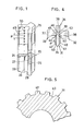
- a blank rod 15 of red brass having a substantially Y-shaped cross section is formed from a round wire 16 (FIG. 2) which is caused to be processed by a pair of roughing rolls 17,18 for rough rolling, a set of four mutually perpendicular rolls 19,20,21 (three shown) for shaping the wire 16, and then a pair of finishing rolls 22,23 for finish rolling. These rolls are positively driven for intermittently feeding the round wire 16 as it is rolled into the blank rod 15.
- the blank rod 15 thus formed includes a pair of V-shaped diverging legs 24,25 having a pair of longitudinal ribs or ridges 26,27, respectively, on confronting inner surfaces 28,29 thereof.
- Each of the ribs 26,27 is pressed or stamped into a series of projections or teeth 30 spaced an interval or pitch P from each other.
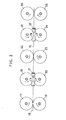
- Such pressing or stamping is performed by a set of rolls 31,32,33 and 34 (FIGS. 2, 3 and 4) rotatable about axes A, B, C and D, respectively, lying in a common plane which extends substantially perpendicularly to the direction of movement of the blank rod 15.
- the rolls 31 - 34 have peripheral surfaces 35,36,37 and 38, respectively, that jointly define a substantially Y-shaped closed space 39 (FIG. 4) which lies in said common plane and is complemental with the cross section of the blank rod 15 for passage of the latter through the space 39.
- FIG. 4 As illustrated in FIG.
- the roll 31 acts as a presser die roll for forming the teeth 30 and its peripheral surface 35 is constituted by a pair of side faces 40,41 that are cross-sectionally V-shaped.
- the rolls 32-34 act as backing rolls for backing up the blank rod 15 as it is pressed by the presser die roll 32.
- the peripheral surface 36 of the roll 32 is defined by faces 42,43, the peripheral surface 37 of the roll 33 by faces 44,45 and the peripheral surface 38 of the roll 34 by a face 46. The cross-sectional contour of the blank rod 15 is thus maintained by these faces of the rolls 31-34.
- a pair of series of die teeth 47,48 project from the faces 40,41 of the presser die roll 31 circumferentially around the latter and are aligned with each other in an axial direction of the presser die roll 31, the die teeth 47,48 in each row being spaced from each other by the pitch P.
- the die teeth 47,48 bite into the ribs 26,27, respectively, causing spaced portions 49 (FIG. 1) below the die teeth 47,48 to be pressed and flow into adjacent regions.
- the blank rod 15 thus provided with the teeth 30 has increased hardness due to work hardening.
- bulges 50,51 tend to be created sideways of the portions 49 and may develop into burrs 53,54 or chips when the blank rod 15 is severed.
- the blank rod 15 is caused to pass between a pair of finishing rolls 55,56 (FIG. 2).
- the rolls 31-34 may be idly rotatable so that they can be rotated only by advancing movement of the blank rod 15 which is caused by the rolls 17-23.
- a movable block 60 has a hole 61 for passage therethrough of the blank rod 15 fed upwardly from the rolls 31-34.
- the block 60 has a front vertical slot 62 which is V-shaped in cross section for receiving a stringer tape 63 with a longitudinal beaded edge 64, which tape is intermittently fed upwardly in a path parallel to the direction in which the blank rod 15 moves upwardly.
- the block 60 also has a channel 65 in which is disposed a fixed cutter blade 66 having a cutting edge 67 for slicing or cutting off the blank rod 15 into a coupling element blank 68 upon retracing movement of the block 60 away from the stringer tape 63.
- the blank rod 15 is intermittently fed upwardly so that it projects out of the hole 61 by a length Q at a time in order that the sliced coupling element blank 68 will have a thickness equal to the length t.
- the coupling element blank 68 is then retained in a recess 72 at the front end of the channel 65 when the block 60 is retracted to the end of stroke of its reaward movement.
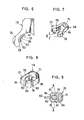
- a punch 69 and a presser 70 are lowered to press the coupling element blank 68 to form a coupling head 71 (FIGS. 7 and 8) at a position where legs 76,77 are joined.
- the punch 69 and the presser 70 are retracted upwardly, and the block 60 is moved forwardly until the coupling element blank 68 arrives at the slot 62 with the legs 76,77 disposed astride the beaded edge 64 of the tape 63.
- a pair of reciprocable punches 73,74 are moved toward each other to clinch the legs 76,77 about the beaded edge 64 of the tape 63 which is held at rest between intermittent movements thereof.
- the blank rod 15 is sliced substantially centrally across each tooth 30 along a line 75 (FIG. 1) such that the coupling element blank 68 has biting teeth 79,80 and 81,82 on the legs 76,77, respectively (FIG. 7).
- a coupling element 78 that is mounted on the stringer tape 63 has on the legs 76, 77 a pair of ends or jaws 83,84, respectively, which grip the tape 63.
- the legs 76,77 are forcibly clamped around the beaded edge 64 so that the teeth 79-82 bite into the beaded edge 64 (FIG. 10).
- the coupling element 78 is secured to the stringer tape 63 with increased holding power against lateral or longitudinal pull tending to displace or dismount the coupling element 78.
- a modified coupling element 85 has a pair of biting teeth 86,87 on the inner surface of one leg 88 and a single biting tooth 89 on the other leg 90, the tooth 89 being positioned in offset relation to the biting teeth 86,87.
- Such biting teeth 86,87 and 89 can be formed by a die roll 57 (FIG. 14) having one of series of die teeth 58 on the die roll 57 displaced out of alignment with another series of teeth 59 by half the pitch P in an axial direction of the die roll 57.
- the coupling element 85 is mounted more securely on a stringer tape beaded edge 91 (FIG. 13) since the teeth 86,87 and 89 bite into the beaded edge 91 in a complementary offset manner.
Landscapes
- Engineering & Computer Science (AREA)
- Mechanical Engineering (AREA)
- Slide Fasteners (AREA)
Applications Claiming Priority (2)
| Application Number | Priority Date | Filing Date | Title |
|---|---|---|---|
| JP139706/79 | 1979-10-29 | ||
| JP54139706A JPS5927667B2 (ja) | 1979-10-29 | 1979-10-29 | スライドフアスナ−用エレメントの成形方法とその装置 |
Publications (3)
| Publication Number | Publication Date |
|---|---|
| EP0028358A2 true EP0028358A2 (fr) | 1981-05-13 |
| EP0028358A3 EP0028358A3 (en) | 1982-07-28 |
| EP0028358B1 EP0028358B1 (fr) | 1985-01-09 |
Family
ID=15251515
Family Applications (1)
| Application Number | Title | Priority Date | Filing Date |
|---|---|---|---|
| EP80106442A Expired EP0028358B1 (fr) | 1979-10-29 | 1980-10-22 | Procédé et appareil pour fabriquer des éléments de fermetures à glissières |
Country Status (9)
| Country | Link |
|---|---|
| US (1) | US4388751A (fr) |
| EP (1) | EP0028358B1 (fr) |
| JP (1) | JPS5927667B2 (fr) |
| KR (1) | KR850000972B1 (fr) |
| AU (1) | AU520226B2 (fr) |
| BR (1) | BR8006811A (fr) |
| CA (1) | CA1157246A (fr) |
| DE (1) | DE3069947D1 (fr) |
| ES (1) | ES496342A0 (fr) |
Cited By (5)
| Publication number | Priority date | Publication date | Assignee | Title |
|---|---|---|---|---|
| EP0578171A3 (en) * | 1992-07-06 | 1994-06-15 | Yoshida Kogyo Kk | Slide fastener coupling element forming apparatus |
| EP0578178A3 (en) * | 1992-07-06 | 1994-06-15 | Yoshida Kogyo Kk | Method and apparatus for manufacturing slide fastener coupling elements |
| EP0580064A3 (fr) * | 1992-07-22 | 1994-08-03 | Yoshida Kogyo Kk | |
| EP0698354A2 (fr) | 1994-08-24 | 1996-02-28 | Ykk Corporation | Eléments d'accouplement pour fermetures à glissière ainsi que leur procédé et dispositif de fabrication |
| CN1309329C (zh) * | 2002-04-11 | 2007-04-11 | Ykk株式会社 | 用于制成拉链链牙的金属线材 |
Families Citing this family (12)
| Publication number | Priority date | Publication date | Assignee | Title |
|---|---|---|---|---|
| JPS58116946A (ja) * | 1981-12-29 | 1983-07-12 | Yoshida Kogyo Kk <Ykk> | スライドフアスナ−用務歯成形装置 |
| JPH07969Y2 (ja) * | 1986-09-24 | 1995-01-18 | ワイケイケイ株式会社 | スライドフアスナ−用上止め具取付け装置 |
| US6958563B2 (en) * | 2003-01-16 | 2005-10-25 | Energy Conversion Systems Holdings, Llc | Riser commutators |
| JP4587840B2 (ja) * | 2005-02-25 | 2010-11-24 | Ykk株式会社 | ファスナーストリンガ連続製造装置 |
| CN101147946B (zh) * | 2006-09-19 | 2010-10-06 | 东莞大兴拉链厂有限公司 | 一种三点粟米牙金属拉链的制造工艺及其成型模具 |
| CN100512999C (zh) * | 2006-09-20 | 2009-07-15 | 东莞大兴拉链厂有限公司 | 双向金属拉链制造工艺 |
| CN101152658B (zh) * | 2006-09-27 | 2010-10-06 | 东莞大兴拉链厂有限公司 | 一种雕花金属拉链的制造工艺及其成型模具 |
| CN102319840B (zh) * | 2011-09-05 | 2013-08-28 | 广东顺德三扬科技有限公司 | 一种啮合元件叠料检测控制装置 |
| CN102672077A (zh) * | 2012-05-26 | 2012-09-19 | 广东辉丰科技股份有限公司 | 一种不锈钢牙拉链及其制备方法 |
| CN102728749A (zh) * | 2012-07-10 | 2012-10-17 | 广东辉丰科技股份有限公司 | 一种二号金属拉链的制备方法 |
| EP2946683B1 (fr) * | 2013-01-18 | 2017-08-23 | YKK Corporation | Élément de fermeture et bande de fermeture |
| CN113303567B (zh) * | 2021-06-02 | 2025-06-27 | 孙发 | 一种拉链及其制造工艺 |
Family Cites Families (16)
| Publication number | Priority date | Publication date | Assignee | Title |
|---|---|---|---|---|
| US2734546A (en) * | 1956-02-14 | Firing | ||
| GB121607A (en) * | 1917-12-18 | 1919-06-26 | Paul Ferdinand Emon | Improved Cold Drawing of Metals by Rolling. |
| US1467015A (en) * | 1919-07-10 | 1923-09-04 | Hookless Fastener Co | Method and machine for making fasteners |
| US1837011A (en) * | 1926-10-29 | 1931-12-15 | Mishawaka Rurber And Woolen Mf | Fastener |
| US2141200A (en) * | 1935-09-03 | 1938-12-27 | Talon Inc | Machine for making fastener stringers |
| US2397965A (en) * | 1940-01-08 | 1946-04-09 | Alphonse W Hunz | Rolled tooth bar |
| FR53514E (fr) * | 1943-11-19 | 1946-03-04 | Perfectionnements apportés aux dents de fermetures à glissière et à leur fabrication | |
| US2596888A (en) * | 1948-05-06 | 1952-05-13 | Samuel L Cohn | Zipper and method of producing the same |
| US2763051A (en) * | 1949-05-11 | 1956-09-18 | Scovill Manufacturing Co | Machine for making fastener stringers |
| GB792437A (en) * | 1955-02-22 | 1958-03-26 | Hansen Harry | Apparatus for use in the production of sliding fastener elements |
| US3066387A (en) * | 1958-06-20 | 1962-12-04 | Resinoid Eng Corp | Method of making commutators |
| GB900156A (en) * | 1960-03-07 | 1962-07-04 | Talon Inc | Fastener elements for slide fasteners and method and apparatus for making such elements |
| US3068549A (en) * | 1961-03-22 | 1962-12-18 | Scovill Manufacturing Co | Apparatus for manufacturing zipper fastener stringers |
| US3187540A (en) * | 1963-03-15 | 1965-06-08 | Scovill Manufacturing Co | Process and apparatus for making zipper fastener elements |
| JPS5748405Y2 (fr) * | 1974-07-16 | 1982-10-23 | ||
| JPS5264106U (fr) * | 1975-10-31 | 1977-05-12 |
-
1979
- 1979-10-29 JP JP54139706A patent/JPS5927667B2/ja not_active Expired
-
1980
- 1980-10-20 KR KR1019800004022A patent/KR850000972B1/ko not_active Expired
- 1980-10-22 DE DE8080106442T patent/DE3069947D1/de not_active Expired
- 1980-10-22 EP EP80106442A patent/EP0028358B1/fr not_active Expired
- 1980-10-23 BR BR8006811A patent/BR8006811A/pt unknown
- 1980-10-28 AU AU63759/80A patent/AU520226B2/en not_active Ceased
- 1980-10-28 ES ES496342A patent/ES496342A0/es active Granted
- 1980-10-28 CA CA000363436A patent/CA1157246A/fr not_active Expired
- 1980-10-29 US US06/201,695 patent/US4388751A/en not_active Expired - Lifetime
Cited By (13)
| Publication number | Priority date | Publication date | Assignee | Title |
|---|---|---|---|---|
| CN1047116C (zh) * | 1992-07-06 | 1999-12-08 | Ykk株式会社 | 拉链链合元件的成形装置 |
| EP0578178A3 (en) * | 1992-07-06 | 1994-06-15 | Yoshida Kogyo Kk | Method and apparatus for manufacturing slide fastener coupling elements |
| US5357663A (en) * | 1992-07-06 | 1994-10-25 | Yoshida Kogyo K.K. | Slide fastener coupling element forming apparatus |
| EP0578171A3 (en) * | 1992-07-06 | 1994-06-15 | Yoshida Kogyo Kk | Slide fastener coupling element forming apparatus |
| EP0580064A3 (fr) * | 1992-07-22 | 1994-08-03 | Yoshida Kogyo Kk | |
| US5361471A (en) * | 1992-07-22 | 1994-11-08 | Yoshida Kogyo K.K. | Slide fastener coupling element forming apparatus and cutting punch |
| EP0698354A2 (fr) | 1994-08-24 | 1996-02-28 | Ykk Corporation | Eléments d'accouplement pour fermetures à glissière ainsi que leur procédé et dispositif de fabrication |
| EP0698354A3 (fr) * | 1994-08-24 | 1997-09-17 | Ykk Corp | Eléments d'accouplement pour fermetures à glissière ainsi que leur procédé et dispositif de fabrication |
| US5778519A (en) * | 1994-08-24 | 1998-07-14 | Ykk Corporation | Apparatus for forming "slide fastener elements" |
| US5926934A (en) * | 1994-08-24 | 1999-07-27 | Ykk Corporation | Method for forming a row of slide fastener elements |
| CN1056791C (zh) * | 1994-08-24 | 2000-09-27 | Ykk株式会社 | 拉链链牙及其成形方法和设备 |
| CN1309329C (zh) * | 2002-04-11 | 2007-04-11 | Ykk株式会社 | 用于制成拉链链牙的金属线材 |
| EP1352583B1 (fr) * | 2002-04-11 | 2013-08-14 | YKK Corporation | Tige métallique pour la fabrication d'éléments d'accouplement de fermeture à glissière et un élément d'accouplement formé à partir de celle-ci |
Also Published As
| Publication number | Publication date |
|---|---|
| EP0028358A3 (en) | 1982-07-28 |
| ES8301129A1 (es) | 1982-12-16 |
| JPS5662635A (en) | 1981-05-28 |
| EP0028358B1 (fr) | 1985-01-09 |
| KR830004048A (ko) | 1983-07-06 |
| DE3069947D1 (en) | 1985-02-21 |
| JPS5927667B2 (ja) | 1984-07-07 |
| BR8006811A (pt) | 1981-05-05 |
| ES496342A0 (es) | 1982-12-16 |
| KR850000972B1 (ko) | 1985-07-05 |
| AU520226B2 (en) | 1982-01-21 |
| CA1157246A (fr) | 1983-11-22 |
| AU6375980A (en) | 1981-05-07 |
| US4388751A (en) | 1983-06-21 |
Similar Documents
| Publication | Publication Date | Title |
|---|---|---|
| EP0028358A2 (fr) | Procédé et appareil pour fabriquer des éléments de fermetures à glissières | |
| EP0608770B1 (fr) | Elément d'accouplement pour une fermeture à glissière et procédé de fabrication | |
| JP6833829B2 (ja) | ファスナーエレメント、ファスナーエレメントの製造装置、及びファスナーエレメントの製造方法 | |
| EP0630706B1 (fr) | Méthode et dispositif pour le formage d'un élément d'accouplement pour fermeture à glissière | |
| CA1188494A (fr) | Methode et appareil pour fabriquer des elements de couplage pour des fermetures a glissiere | |
| GB1600150A (en) | Method and apparatus for manufacture of coupling elements of slide fasteners | |
| CN211161481U (zh) | 一种连续送料冲压模具 | |
| US2221740A (en) | Manufacture of slide fastener elements | |
| US3461708A (en) | Method of forming conduit clamps | |
| US2116712A (en) | Method of making fastener units | |
| EP0090528B1 (fr) | Procédé et appareil pour fabriquer des circlips | |
| US4010520A (en) | Coupling element for slide fastener | |
| US4055882A (en) | Method of making a coupling element for a slide fastener | |
| EP0064764B1 (fr) | Procédé et appareil de fabrication des éléments de fermetures à glissière | |
| US2148672A (en) | Method of making fastener elements | |
| US4349953A (en) | Method of manufacturing slide fastener coupling elements | |
| US3446009A (en) | Methods and apparatus for making staples | |
| US2106129A (en) | Method of making separable fasteners | |
| US3091024A (en) | Method of making fastener elements for slide fasteners | |
| US4112674A (en) | Machinery for the mass production of pronged members or of continuous strips of pronged members | |
| US3548483A (en) | Apparatus and method of manufacturing fasteners | |
| US2989803A (en) | Method of making slide fastener elements | |
| EP2708151A1 (fr) | Procédé pour la fabrication d'éléments d'interconnexion d'une fermeture à glissière | |
| CA2067922C (fr) | Methode de formage de logements creux dans une glissiere de fermeture-eclair | |
| US2490864A (en) | Method of manufacturing interlocking members for sliding clasp fasteners |
Legal Events
| Date | Code | Title | Description |
|---|---|---|---|
| PUAI | Public reference made under article 153(3) epc to a published international application that has entered the european phase |
Free format text: ORIGINAL CODE: 0009012 |
|
| AK | Designated contracting states |
Designated state(s): BE DE FR GB IT NL |
|
| ITCL | It: translation for ep claims filed |
Representative=s name: JACOBACCI CASETTA & PERANI S.P.A. |
|
| 17P | Request for examination filed |
Effective date: 19810812 |
|
| DET | De: translation of patent claims | ||
| PUAL | Search report despatched |
Free format text: ORIGINAL CODE: 0009013 |
|
| AK | Designated contracting states |
Designated state(s): BE DE FR GB IT NL |
|
| ITF | It: translation for a ep patent filed | ||
| GRAA | (expected) grant |
Free format text: ORIGINAL CODE: 0009210 |
|
| AK | Designated contracting states |
Designated state(s): BE DE FR GB IT NL |
|
| REF | Corresponds to: |
Ref document number: 3069947 Country of ref document: DE Date of ref document: 19850221 |
|
| ET | Fr: translation filed | ||
| PLBE | No opposition filed within time limit |
Free format text: ORIGINAL CODE: 0009261 |
|
| STAA | Information on the status of an ep patent application or granted ep patent |
Free format text: STATUS: NO OPPOSITION FILED WITHIN TIME LIMIT |
|
| 26N | No opposition filed | ||
| ITTA | It: last paid annual fee | ||
| ITPR | It: changes in ownership of a european patent |
Owner name: CAMBIO RAGIONE SOCIALE;YKK CORPORATION |
|
| REG | Reference to a national code |
Ref country code: FR Ref legal event code: CD |
|
| NLT1 | Nl: modifications of names registered in virtue of documents presented to the patent office pursuant to art. 16 a, paragraph 1 |
Owner name: YKK CORPORATION TE TOKIO, JAPAN. |
|
| PGFP | Annual fee paid to national office [announced via postgrant information from national office to epo] |
Ref country code: FR Payment date: 19980721 Year of fee payment: 19 |
|
| PGFP | Annual fee paid to national office [announced via postgrant information from national office to epo] |
Ref country code: BE Payment date: 19980727 Year of fee payment: 19 |
|
| PGFP | Annual fee paid to national office [announced via postgrant information from national office to epo] |
Ref country code: GB Payment date: 19981023 Year of fee payment: 19 |
|
| PGFP | Annual fee paid to national office [announced via postgrant information from national office to epo] |
Ref country code: NL Payment date: 19981031 Year of fee payment: 19 |
|
| PGFP | Annual fee paid to national office [announced via postgrant information from national office to epo] |
Ref country code: DE Payment date: 19981130 Year of fee payment: 19 |
|
| PG25 | Lapsed in a contracting state [announced via postgrant information from national office to epo] |
Ref country code: GB Free format text: LAPSE BECAUSE OF NON-PAYMENT OF DUE FEES Effective date: 19991022 |
|
| PG25 | Lapsed in a contracting state [announced via postgrant information from national office to epo] |
Ref country code: BE Free format text: LAPSE BECAUSE OF NON-PAYMENT OF DUE FEES Effective date: 19991031 |
|
| BERE | Be: lapsed |
Owner name: YKK CORP. Effective date: 19991031 |
|
| PG25 | Lapsed in a contracting state [announced via postgrant information from national office to epo] |
Ref country code: NL Free format text: LAPSE BECAUSE OF NON-PAYMENT OF DUE FEES Effective date: 20000501 |
|
| GBPC | Gb: european patent ceased through non-payment of renewal fee |
Effective date: 19991022 |
|
| PG25 | Lapsed in a contracting state [announced via postgrant information from national office to epo] |
Ref country code: FR Free format text: LAPSE BECAUSE OF NON-PAYMENT OF DUE FEES Effective date: 20000630 |
|
| NLV4 | Nl: lapsed or anulled due to non-payment of the annual fee |
Effective date: 20000501 |
|
| PG25 | Lapsed in a contracting state [announced via postgrant information from national office to epo] |
Ref country code: DE Free format text: LAPSE BECAUSE OF NON-PAYMENT OF DUE FEES Effective date: 20000801 |
|
| REG | Reference to a national code |
Ref country code: FR Ref legal event code: ST |