EP0028507B1 - Procédé de façonnage de métal - Google Patents
Procédé de façonnage de métal Download PDFInfo
- Publication number
- EP0028507B1 EP0028507B1 EP80303858A EP80303858A EP0028507B1 EP 0028507 B1 EP0028507 B1 EP 0028507B1 EP 80303858 A EP80303858 A EP 80303858A EP 80303858 A EP80303858 A EP 80303858A EP 0028507 B1 EP0028507 B1 EP 0028507B1
- Authority
- EP
- European Patent Office
- Prior art keywords
- sheet
- knurling
- width
- pattern
- longitudinal edge
- Prior art date
- Legal status (The legal status is an assumption and is not a legal conclusion. Google has not performed a legal analysis and makes no representation as to the accuracy of the status listed.)
- Expired
Links
- 239000002184 metal Substances 0.000 title claims description 29
- 238000000034 method Methods 0.000 title claims description 14
- 238000007493 shaping process Methods 0.000 title claims description 5
- 238000005096 rolling process Methods 0.000 claims description 8
- 238000005482 strain hardening Methods 0.000 claims description 3
- 230000001360 synchronised effect Effects 0.000 claims description 3
- 229910000831 Steel Inorganic materials 0.000 claims description 2
- 230000000694 effects Effects 0.000 claims description 2
- 239000010959 steel Substances 0.000 claims description 2
- 238000010586 diagram Methods 0.000 description 2
- 230000003247 decreasing effect Effects 0.000 description 1
- 230000001105 regulatory effect Effects 0.000 description 1
- 238000000926 separation method Methods 0.000 description 1
Images



Classifications
-
- B—PERFORMING OPERATIONS; TRANSPORTING
- B21—MECHANICAL METAL-WORKING WITHOUT ESSENTIALLY REMOVING MATERIAL; PUNCHING METAL
- B21D—WORKING OR PROCESSING OF SHEET METAL OR METAL TUBES, RODS OR PROFILES WITHOUT ESSENTIALLY REMOVING MATERIAL; PUNCHING METAL
- B21D19/00—Flanging or other edge treatment, e.g. of tubes
- B21D19/005—Edge deburring or smoothing
Definitions
- This invention relates to a method of shaping metal in the form of a parallel-sided elongate sheet to make from it a formed profile.
- a method of shaping metal in the form of a parallel-sided elongate sheet by generating a repeating pattern along the length of at least one longitudinal edge by means of one or more than one knurling wheel which has the effect of reducing the overall width of the sheet is characterised by rolling the sheet prior to generating the pattern to increase its width to the extent required to ensure that the action of the knurling wheel will restore the overall width to substantially its original value; and roll-forming the sheet, after generating the pattern, to a formed profile that is of uniform cross-section except for the said pattern, each operation on the sheet being a cold working step.
- knurling wheels Preferably there are two knurling wheels, one for each longitudinal edge, and the rotation of the knurling wheels is synchronised.
- the rotation of all the knurling wheels is synchronised.
- the width of the sheet is increased by tapering at least one longitudinal edge.
- This method has particular use when applied to a sheet of steel.
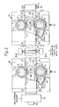
- the apparatus comprises two substantially identical knurling machines 8A, 8B.
- Each knurling machine 8A, 8B comprises two knurling wheels 9, 10 and means for. guiding a metal sheet 11 through the machine in the form of two guide wheels 12, 13 which surround the knurling wheels 9, 10.
- the knurling wheels 9, 10 are inter-connected by a belt 14 and pulley arrangement.
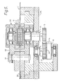
- One of the knurling wheels 9 is connected through its spindle 15 and a gear wheel 16 to an independent gear wheel 17.
- the belt 14 passes round a pulley 18 mounted on the same spindle 19 as the independent gear wheel 17, and a pulley 20 mounted on the spindle 21 of knurling wheel 10.
- the tension in the belt 14 is regulated by passing the belt over a roller 22 which is pulled against the belt by a spring 23.
- the metal sheet 11 moves through each machine 8A, 8B in the direction X.
- Guide wheels 12, 13 keep the longitudinal edges 24, 25 of the sheet 11 perpendicular to the rotational axis of the knurling wheels 9, 10.
- Guide blocks 26, 27 prevent the metal sheet 11 buckling while it passes between the knurling wheels 9, 10.
- the knurling wheels 9, 10 knurl grooves 28 (Fig. 7) in the longitudinal edges 24, 25 of the metal sheet 11.
- the belt 14 and pulley arrangement synchronises the rotation of the two knurling wheels 9, 10 so that a groove is knurled in each longitudinal edge 24, 25 at the same time, the grooves being directly opposite.
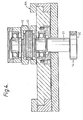
- Each machine 8A, 8B also includes an adjustor 29 for varying the separation of the knurling wheels 9, 10 allowing metal sheets of varying width to be knurled on each machine.
- the adjustor 29 comprises a plate 30 attached to the spindle 15 of the knurling wheel 9 and to pin 31.
- the knurling wheel 9 is moved by rotating adjusting screws 32 mounted on the side of each machine 8A, 8B so that the knurling wheel 9 pivots about the pin 31.
- rollers 33 Situated between the knurling machines 8A, 8B is a pair of rollers 33 ( Figure 6) between which the metal sheet 11 passes.
- the rollers 33 increase the width of the metal sheet 11 by tapering each longitudinal edge 24, 25.
- the arrangement is such that the knurling wheels 9, 10 of the first knurling machine 8A knurl grooves 28 in the longitudinal edges 24, 25 of the metal sheet 11 to approximately half the depth required.
- the rollers 33 put a taper on both corners of each longitudinal edge 24, 25 and slightly increase the width, of the metal sheet 11.
- the knurling wheels 9, 10 of the first knurling machine 8A are driven at a slightly slower rate than the rate at which the rollers 33 rotate. Therefore in use when a metal sheet 11 is fed into the apparatus the knurling wheels 9, 10 of the first knurling machine 8A initially drive the metal sheet 11 through the machine 8A until the sheet reaches the rollers 33, at which time the rollers take over and pull the sheet through the first knurling machine 8A, and drive it towards and through the second knurling machine 8B.
- the knurling wheels 9, 10 of the second knurling machine 8B are free-wheeling.
- a roll-forming machine 35 is positioned at the output of the second knurling machine 8B. On passing through this machine 35 the metal sheet 11 is rolled into the profile of a channel 36 ( Figure 7) of substantially U-shaped cross-section, with the free ends of the limbs 37, 38 turned inwards to define flanges 39, 40 the grooves 28 formed by the knurling machines 8A, 8B being directed towards the base 41 of the channel.
- This invention has the advantage that plain channel and channel with patterned edges can be made to the same size from the same width of strip.
- this invention has been described for rolling a metal sheet into a channel-shape profile, this invention is not restricted to this particular arrangement, but could also be used for forming any other profile that is of uniform cross-section.
Landscapes
- Engineering & Computer Science (AREA)
- Mechanical Engineering (AREA)
- Metal Rolling (AREA)
- Reduction Rolling/Reduction Stand/Operation Of Reduction Machine (AREA)
- Bending Of Plates, Rods, And Pipes (AREA)
- Table Devices Or Equipment (AREA)
- Laminated Bodies (AREA)
Claims (7)
Priority Applications (1)
| Application Number | Priority Date | Filing Date | Title |
|---|---|---|---|
| AT80303858T ATE3376T1 (de) | 1979-11-02 | 1980-10-30 | Verfahren zum metallverformen. |
Applications Claiming Priority (4)
| Application Number | Priority Date | Filing Date | Title |
|---|---|---|---|
| GB7938050 | 1979-11-02 | ||
| GB7938050 | 1979-11-02 | ||
| GB8010903 | 1980-04-01 | ||
| GB8010903 | 1980-04-01 |
Publications (2)
| Publication Number | Publication Date |
|---|---|
| EP0028507A1 EP0028507A1 (fr) | 1981-05-13 |
| EP0028507B1 true EP0028507B1 (fr) | 1983-05-18 |
Family
ID=26273427
Family Applications (1)
| Application Number | Title | Priority Date | Filing Date |
|---|---|---|---|
| EP80303858A Expired EP0028507B1 (fr) | 1979-11-02 | 1980-10-30 | Procédé de façonnage de métal |
Country Status (13)
| Country | Link |
|---|---|
| US (1) | US4357818A (fr) |
| EP (1) | EP0028507B1 (fr) |
| AU (1) | AU533660B2 (fr) |
| CA (1) | CA1145595A (fr) |
| CH (1) | CH650173A5 (fr) |
| DE (1) | DE3063364D1 (fr) |
| DK (1) | DK159530C (fr) |
| ES (1) | ES496438A0 (fr) |
| FR (1) | FR2468421B1 (fr) |
| HK (1) | HK32484A (fr) |
| IT (1) | IT1174312B (fr) |
| MY (1) | MY8500346A (fr) |
| NO (1) | NO150867C (fr) |
Families Citing this family (4)
| Publication number | Priority date | Publication date | Assignee | Title |
|---|---|---|---|---|
| DE19512414A1 (de) * | 1995-04-03 | 1996-10-10 | Hilti Ag | Verfahren zur Herstellung einer Profilschiene |
| ES2383338T3 (es) * | 2007-08-16 | 2012-06-20 | Hilti Aktiengesellschaft | Método para reducción del grosor de materiales de laminación de una única pieza |
| CN111421052A (zh) * | 2019-12-19 | 2020-07-17 | 东北大学无锡研究院 | 一种折叠斜腿哈芬槽钢及其制备方法 |
| CN116713818B (zh) * | 2023-05-30 | 2026-04-21 | 重庆东憧铝业有限公司 | 一种组合式滚花、切片装置及加工方法 |
Citations (1)
| Publication number | Priority date | Publication date | Assignee | Title |
|---|---|---|---|---|
| GB2050549A (en) * | 1979-05-25 | 1981-01-07 | Bicc Ltd | Anchoring nuts or screws |
Family Cites Families (13)
| Publication number | Priority date | Publication date | Assignee | Title |
|---|---|---|---|---|
| US1963724A (en) * | 1930-06-27 | 1934-06-19 | Taylor James Hall | Apparatus for upsetting plate edges |
| US2090706A (en) * | 1936-01-22 | 1937-08-24 | Morgan Construction Co | Edge rolling method and apparatus |
| US2292810A (en) * | 1940-07-29 | 1942-08-11 | Bundy Tubing Co | Method and apparatus for making tube |
| DE1602021U (de) | 1949-12-14 | 1950-02-23 | Albert Wernecke | Hebelverschluss fuer die rueckwand von lastkraftwagen. |
| US3006401A (en) * | 1957-10-23 | 1961-10-31 | Acme Steel Co | Apparatus for conditioning metal strip having non-uniform stresses therein |
| US3206965A (en) * | 1963-06-19 | 1965-09-21 | Gauer Walter | Sheet metal edging apparatus |
| US3267252A (en) * | 1964-12-23 | 1966-08-16 | American Mach & Foundry | Edge conditioning of metal strips by high frequency resistance heating |
| US3400566A (en) | 1966-12-13 | 1968-09-10 | Gauer Walter | Sheet metal edging apparatus |
| GB1276019A (en) | 1967-04-21 | 1972-06-01 | Archer Products Inc | Rolling apparatus for use in rounding the edges of strip metal |
| DE1602021A1 (de) * | 1967-10-26 | 1970-05-06 | Arbed Vereinigte Huettenwerke | Verfahren zur Herstellung von auf der Schmalseite profilierten Baendern |
| US3587275A (en) * | 1968-08-21 | 1971-06-28 | Francis P Brennan | Edge rolling mechanism |
| US3690139A (en) * | 1969-11-13 | 1972-09-12 | Francis P Brennan | Edge conditioning mechanism |
| US3877275A (en) * | 1973-08-22 | 1975-04-15 | Unistrut Corp | Cold roll reduction and forming method |
-
1980
- 1980-10-27 US US06/201,079 patent/US4357818A/en not_active Expired - Lifetime
- 1980-10-28 AU AU63777/80A patent/AU533660B2/en not_active Ceased
- 1980-10-30 DK DK459880A patent/DK159530C/da not_active IP Right Cessation
- 1980-10-30 CH CH8089/80A patent/CH650173A5/de not_active IP Right Cessation
- 1980-10-30 EP EP80303858A patent/EP0028507B1/fr not_active Expired
- 1980-10-30 DE DE8080303858T patent/DE3063364D1/de not_active Expired
- 1980-10-31 CA CA000363741A patent/CA1145595A/fr not_active Expired
- 1980-10-31 ES ES496438A patent/ES496438A0/es active Granted
- 1980-10-31 IT IT50050/80A patent/IT1174312B/it active
- 1980-10-31 NO NO803270A patent/NO150867C/no unknown
- 1980-10-31 FR FR8023401A patent/FR2468421B1/fr not_active Expired
-
1984
- 1984-04-12 HK HK324/84A patent/HK32484A/xx not_active IP Right Cessation
-
1985
- 1985-12-30 MY MY346/85A patent/MY8500346A/xx unknown
Patent Citations (1)
| Publication number | Priority date | Publication date | Assignee | Title |
|---|---|---|---|---|
| GB2050549A (en) * | 1979-05-25 | 1981-01-07 | Bicc Ltd | Anchoring nuts or screws |
Also Published As
| Publication number | Publication date |
|---|---|
| DK159530B (da) | 1990-10-29 |
| DK159530C (da) | 1991-04-02 |
| DK459880A (da) | 1981-05-03 |
| NO150867B (no) | 1984-09-24 |
| EP0028507A1 (fr) | 1981-05-13 |
| NO803270L (no) | 1981-05-04 |
| HK32484A (en) | 1984-04-19 |
| AU533660B2 (en) | 1983-12-01 |
| NO150867C (no) | 1985-01-09 |
| ES8201857A1 (es) | 1982-01-01 |
| FR2468421A1 (fr) | 1981-05-08 |
| IT1174312B (it) | 1987-07-01 |
| CA1145595A (fr) | 1983-05-03 |
| AU6377780A (en) | 1981-05-07 |
| CH650173A5 (de) | 1985-07-15 |
| US4357818A (en) | 1982-11-09 |
| ES496438A0 (es) | 1982-01-01 |
| IT8050050A0 (it) | 1980-10-31 |
| FR2468421B1 (fr) | 1985-11-08 |
| MY8500346A (en) | 1985-12-31 |
| DE3063364D1 (en) | 1983-07-07 |
Similar Documents
| Publication | Publication Date | Title |
|---|---|---|
| EP0230644B1 (fr) | Arrangement pour décalaminer des feuillards d'acier laminés à chaud | |
| US5791185A (en) | Rotary apparatus with moveable die | |
| US4852383A (en) | Press apparatus for reducing widths of hot slabs | |
| HK1007454B (en) | Rotary apparatus with moveable die | |
| CA1145595A (fr) | Methode de formage du metal | |
| JPS5947617B2 (ja) | テ−パ−リ−フスプリングの製造法 | |
| DE3622926C2 (de) | Kontinuierliches mehrstufiges Walzwerk | |
| GB2061788A (en) | A method of shaping metal sheet | |
| JPH0250812B2 (fr) | ||
| CA1070990A (fr) | Methode et appareil de laminage de toles minces a chaud | |
| US3777530A (en) | Method of weakening strip material in section rolling processes | |
| GB2095595A (en) | Sheet material and method of producing formations in continuously processed material | |
| DE69109945T2 (de) | Umkehrbares Walzverfahren. | |
| CN2122024U (zh) | 一种焊管坯料纵剪装置 | |
| JPH07284802A (ja) | 異形条の製造方法および製造装置 | |
| KR850000795B1 (ko) | 금속을 성형시키는 방법 | |
| EP1786577B1 (fr) | Procede de laminage d'une bande metallique | |
| US2442850A (en) | Method of and apparatus for making flat metal tubes | |
| JPH0139847B2 (fr) | ||
| GB2147838A (en) | A method of shaping metal | |
| CN222970661U (zh) | 铝条加工用滚压式校直装置 | |
| EP0233553B1 (fr) | Dresseuse à rouleaux | |
| AU724954B2 (en) | Rotary apparatus with moveable die | |
| SU845758A3 (ru) | Устройство дл автоматического регулирова-Ни фОРМы МЕТАлличЕСКОй пОлОСы | |
| DD152500A1 (de) | Verfahren zum zerteilen von breiten metallbaendern |
Legal Events
| Date | Code | Title | Description |
|---|---|---|---|
| PUAI | Public reference made under article 153(3) epc to a published international application that has entered the european phase |
Free format text: ORIGINAL CODE: 0009012 |
|
| AK | Designated contracting states |
Designated state(s): AT DE LU NL SE |
|
| 17P | Request for examination filed |
Effective date: 19810609 |
|
| GRAA | (expected) grant |
Free format text: ORIGINAL CODE: 0009210 |
|
| AK | Designated contracting states |
Designated state(s): AT DE LU NL SE |
|
| REF | Corresponds to: |
Ref document number: 3376 Country of ref document: AT Date of ref document: 19830615 Kind code of ref document: T |
|
| RAP2 | Party data changed (patent owner data changed or rights of a patent transferred) |
Owner name: BICC PUBLIC LIMITED COMPANY |
|
| REF | Corresponds to: |
Ref document number: 3063364 Country of ref document: DE Date of ref document: 19830707 |
|
| PGFP | Annual fee paid to national office [announced via postgrant information from national office to epo] |
Ref country code: LU Payment date: 19830926 Year of fee payment: 4 |
|
| PG25 | Lapsed in a contracting state [announced via postgrant information from national office to epo] |
Ref country code: LU Free format text: LAPSE BECAUSE OF NON-PAYMENT OF DUE FEES Effective date: 19831031 |
|
| PLBE | No opposition filed within time limit |
Free format text: ORIGINAL CODE: 0009261 |
|
| STAA | Information on the status of an ep patent application or granted ep patent |
Free format text: STATUS: NO OPPOSITION FILED WITHIN TIME LIMIT |
|
| 26N | No opposition filed | ||
| NLS | Nl: assignments of ep-patents |
Owner name: VANTRUNK ENGINEERING LIMITED TE RUNCORN, GROOT-BRI |
|
| EAL | Se: european patent in force in sweden |
Ref document number: 80303858.7 |
|
| PGFP | Annual fee paid to national office [announced via postgrant information from national office to epo] |
Ref country code: SE Payment date: 19971127 Year of fee payment: 18 Ref country code: AT Payment date: 19971127 Year of fee payment: 18 |
|
| PG25 | Lapsed in a contracting state [announced via postgrant information from national office to epo] |
Ref country code: AT Free format text: LAPSE BECAUSE OF NON-PAYMENT OF DUE FEES Effective date: 19981030 |
|
| PG25 | Lapsed in a contracting state [announced via postgrant information from national office to epo] |
Ref country code: SE Free format text: LAPSE BECAUSE OF NON-PAYMENT OF DUE FEES Effective date: 19981031 |
|
| EUG | Se: european patent has lapsed |
Ref document number: 80303858.7 |
|
| PGFP | Annual fee paid to national office [announced via postgrant information from national office to epo] |
Ref country code: NL Payment date: 19991029 Year of fee payment: 20 |
|
| PGFP | Annual fee paid to national office [announced via postgrant information from national office to epo] |
Ref country code: DE Payment date: 19991102 Year of fee payment: 20 |
|
| PG25 | Lapsed in a contracting state [announced via postgrant information from national office to epo] |
Ref country code: NL Free format text: LAPSE BECAUSE OF EXPIRATION OF PROTECTION Effective date: 20001030 |
|
| NLV7 | Nl: ceased due to reaching the maximum lifetime of a patent |
Effective date: 20001030 |