EP0028557A2 - Injektionsspritze - Google Patents
Injektionsspritze Download PDFInfo
- Publication number
- EP0028557A2 EP0028557A2 EP80401510A EP80401510A EP0028557A2 EP 0028557 A2 EP0028557 A2 EP 0028557A2 EP 80401510 A EP80401510 A EP 80401510A EP 80401510 A EP80401510 A EP 80401510A EP 0028557 A2 EP0028557 A2 EP 0028557A2
- Authority
- EP
- European Patent Office
- Prior art keywords
- piston
- cylinder
- chamber
- rod
- section
- Prior art date
- Legal status (The legal status is an assumption and is not a legal conclusion. Google has not performed a legal analysis and makes no representation as to the accuracy of the status listed.)
- Granted
Links
- 238000002347 injection Methods 0.000 title abstract description 21
- 239000007924 injection Substances 0.000 title abstract description 21
- 239000007788 liquid Substances 0.000 claims description 21
- 239000012530 fluid Substances 0.000 claims description 9
- 210000001519 tissue Anatomy 0.000 description 6
- 238000006073 displacement reaction Methods 0.000 description 4
- 230000008595 infiltration Effects 0.000 description 4
- 238000001764 infiltration Methods 0.000 description 4
- 230000000694 effects Effects 0.000 description 3
- 210000003813 thumb Anatomy 0.000 description 3
- 210000000988 bone and bone Anatomy 0.000 description 2
- 210000000078 claw Anatomy 0.000 description 2
- 210000003811 finger Anatomy 0.000 description 2
- 210000004872 soft tissue Anatomy 0.000 description 2
- BTFMCMVEUCGQDX-UHFFFAOYSA-N 1-[10-[3-[4-(2-hydroxyethyl)-1-piperidinyl]propyl]-2-phenothiazinyl]ethanone Chemical compound C12=CC(C(=O)C)=CC=C2SC2=CC=CC=C2N1CCCN1CCC(CCO)CC1 BTFMCMVEUCGQDX-UHFFFAOYSA-N 0.000 description 1
- 206010002091 Anaesthesia Diseases 0.000 description 1
- 230000037005 anaesthesia Effects 0.000 description 1
- 230000003444 anaesthetic effect Effects 0.000 description 1
- 230000000747 cardiac effect Effects 0.000 description 1
- 230000003247 decreasing effect Effects 0.000 description 1
- 238000000034 method Methods 0.000 description 1
- 229960004265 piperacetazine Drugs 0.000 description 1
- 239000004848 polyfunctional curative Substances 0.000 description 1
- 229920001296 polysiloxane Polymers 0.000 description 1
- 238000002360 preparation method Methods 0.000 description 1
- 238000001356 surgical procedure Methods 0.000 description 1
Images

Classifications
-
- A—HUMAN NECESSITIES
- A61—MEDICAL OR VETERINARY SCIENCE; HYGIENE
- A61M—DEVICES FOR INTRODUCING MEDIA INTO, OR ONTO, THE BODY; DEVICES FOR TRANSDUCING BODY MEDIA OR FOR TAKING MEDIA FROM THE BODY; DEVICES FOR PRODUCING OR ENDING SLEEP OR STUPOR
- A61M5/00—Devices for bringing media into the body in a subcutaneous, intra-vascular or intramuscular way; Accessories therefor, e.g. filling or cleaning devices, arm-rests
- A61M5/178—Syringes
- A61M5/20—Automatic syringes, e.g. with automatically actuated piston rod, with automatic needle injection, filling automatically
- A61M5/2053—Media being expelled from injector by pressurised fluid or vacuum
Definitions
- the invention relates to a syringe comprising a pressurized fluid cylinder which provides the force necessary for the ejection of a liquid or a paste.
- a syringe is well suited when it comes to pricking into compact tissues where the infiltration of a liquid is difficult such as, for example, in bone tissue as it frequently occurs in dental surgery.
- the syringe of the invention is not limited to this use; on the contrary, it brings by its new conception the possibility of using it in a more universal way. Indeed, it also allows the execution of punctures in soft tissues with the same softness and the same precise control which is achieved with purely manual syringes. Conversely, it can also be used for the infiltration of a liquid into the tissues, without needle, by a simple projection under high pressure.
- Syringes comprising a cylinder are already known; a description is found in US patent No. 3,605,745 and in French patent No. 72-27030 (2,193,626).
- the actuator comprises a piston on which the fluid under pressure acts. So that the effect of the pressure is more easily controllable, the fluid is admitted on the two sides of the piston and it is the differential pressure which is created between the two sides which causes the displacement of the piston in the direction of l 'injection.
- the differential pressure is established as a result of the operation by the user of a valve for closing or opening a leak orifice. This valve has a short stroke. Furthermore, its open position is completely independent of the position of the piston of the cylinder and, consequently, of the quantity of liquid injected. The user is therefore in no way informed either about the actual speed of the injection or about the volume injected at a mo-. given.
- the main object of the invention is to provide a syringe assisted by a cylinder through which the user is informed at all times about the volume injected and the injection speed.
- the operator adjusts himself, from start to finish, the speed at which the injection is made; in fact the user imposes and modifies as he wishes, at any time, the speed or, which amounts to the same thing, the flow rate of the injected liquid.
- At least one communication channel exists between the second chamber and the outside of the cylinder; this channel, or each of the communication channels has an inlet orifice open in the second chamber and an outlet orifice open to the outside and one of these two orifices is located so as to be closed or cleared at will by the user during the movement of an element mounted movable relative to the cylinder in correspondence with the movements of the second piston.
- the communication channel extends in the rod of the second piston and its outlet orifice is located on an extension of this rod outside the cylinder.
- the communication channel comprises a first section extending between the second chamber and the first chamber through the second piston and / or the rod of this second piston, and a second section which crosses the wall of the cylinder between the first chamber and the outside of the cylinder.
- the movable element passes through the end wall of the cylinder opposite the side of the ejection, this rod ending inside the cylinder by an end capable of closing the inlet orifice. of the communication channel opening into the second chamber.
- the mobile element passes through the end wall of the cylinder on the ejection side and it is provided inside the cylinder with a shutter member for the opening orifice of the first section inside the first chamber.
- the opening orifice of the first section of the communication channel is located on a face facing the piston with a radial extension of the piston rod and the movable element is provided with the inside of the cylinder of a flange mounted sliding on the piston rod between this piston and said radial extension.
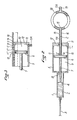
- An injection syringe comprises a first cylinder 1 or an attached cartridge 1 containing a liquid 2 to be injected by a needle 3 under the effect of a first piston 4 which is in direct contact with the liquid 2.
- This syringe also comprises in rear of the cylinder 1 or of the cartridge 1, a cylinder 5 of a jack containing a second piston 6; the latter is mounted at one end of a piston rod 7 which passes through the end wall 8 on the side of the needle 3 . or, more generally, on the side of the ejection of the li quide 2 out of the cartridge 1.
- the other end of the piston rod 7 acts directly on the first piston 4.
- the second piston 6 divides the cylinder 5 of the jack into a first chamber 9 located on the side of the liquid 2 to be ejected and into a second chamber 10 located on the opposite side.
- An orifice 11 for supplying pressurized fluid opens in the second chamber 10. The exact position of this orifice is not of great importance as long as the second chamber 10 can be adequately supplied .
- the orifice 11 may be that of a channel 11A passing through the side wall of the cylinder 5, as shown in solid lines in FIG. 1 and in phantom in FIG. 2, or passing through the end wall 12 on the side opposite to the ejection (FIG. 4), or the orifice of a channel drilled in a rod 13 fixed to the piston 6 and passing through the end wall 12 as can be seen in FIG. 2.
- this channel there is at least one communication channel between the second chamber 10 and the outside of the cylinder 5; this channel has an inlet orifice 14 open in the second chamber and an outlet orifice 15 open to the outside; in addition, at least one of these two orifices 14, 15 is located so as to be closed or released at will by the user during the movement of an element 16 mounted movable relative to the cylinder 5-in correspondence with the movements of the second piston 6.
- the element 16 is movable in correspondence with the piston 6, we mean that the element 16 has a stroke equal to that of the piston 6 and, also, that any movement of the piston 6 in its displacements, in particular in the direction of injection, accompanies a corresponding movement of the mobile element 16.
- the corresponding movement of the mobile element 16 takes place in the longitudinal direction relative to the cylinder 5.
- the communication channel designates, in the spirit of the invention, any passage, single or multiple lanes, in a single section or in several sections, which may exist between the second chamber 10 and the outside of the cylinder 5 .
- each channel, C, C ', C ", C"', etc ... has an inlet port 14 and an outlet port 15, and the movable element is capable of releasing and then closing successively each orifice 15 of the channels.
- FIG. 2 there is a single communication channel C which merges with part of the length of the channel 11A.
- the inlet orifice 14 of the channel C is coincident with the orifice 11 for supplying the second chamber 10.
- the rod 13 has in its end part a ring 18, hollow, which constitutes two circular branches of the channel 11 A after an extreme nozzle 19 for supplying pressurized gas.
- the outlet 15 of the channel C is placed inside the ring 18 so that it can be easily closed or released by the operator's thumb, inserted into this ring 18 in the same way as in a ring classic of a manual syringe.
- the part of the rod 13 located between the cylinder 6 and the ring 18 also constitutes the mobile element 16.
- the communication channel C is composed of a first section C1 and a second section C2.
- the first section C1 extends between the second chamber 10 and the first chamber 9 through the piston 6 and the piston rod 7; the second section C2 crosses the wall of the cylinder 5 between the first chamber 9 and the outside.
- the section C1 is drilled coaxially in the piston 6 then in the piston rod 7 and it ends in a radial part in the latter rod.
- the section C1 opens in the first chamber 9 through an opening orifice 20 situated on the lateral face of the rod 7;
- the movable element 16 passes coaxially through the end wall 12, opposite the side of the injection, of the cylinder 5 and ends inside the latter by a suitable conical end 21 capable of closing the flared inlet orifice 14 of the section C1.
- the conical end 21 has a diameter greater than that of the rod 16 and it is caught between folded claws 22 which extend from the neighboring face of the piston 6. These claws leave a play in the longitudinal direction at the conical end 21.
- the piston rod 7 is provided with a radial extension 23 in which the radial part of the section C1 extends; this extension 23 is spaced from the piston 6 and the section C1 ends with an opening orifice 20 located in the face of the extension 23 facing the piston 6.
- the movable element 16 passes through the end wall 8, on the side of the ejection of the cylinder 5, and ends inside the latter by a flange 24 slidably mounted on the piston rod 7 between the piston 6 and the radial extension 23.
- the flange 24 carries a shutter member 25 capable of closing the opening orifice 20 of the section C1 inside the first chamber 9.
- the movable element 16 crosses the end wall 8 of the cylinder 5, and can slide in longitudinal direction along the cartridge 1.
- the user controls the injection speed himself by means of the speed at which he moves the movable element 16.
- the piston 6 performs the ejection of the liquid by following the movement of the mobile element 16.
- the infiltration of the liquid 2 hardly occurs in a bone tissue
- the user moves the mobile element 16 slowly at a speed that the piston 6 can accompany with regularity.
- the movement of the movable member can be even slower, so that sudden ejection is avoided. This is important when you consider that an injection of an anesthetic liquid given too quickly can be the cause of cardiac incidents and that, done too suddenly, it can cause tissue tears.
- the length of the movement of the movable element 16 is the same as that of the pistons 6 and 4; it is proportional to the quantity of liquid ejected. Consequently, the stroke which the user causes the movable element 16 to complete informs him of the corresponding fraction of ejected liquid. It can therefore accelerate or slow down the movement of the movable element 16 accordingly or even interrupt it in order to make only a partial injection in certain circumstances.
- the movement can be as slow as it takes for the dosage to be precise; moreover, the movable element 16 can carry a graduation.
- the piston moves at a speed as slow as the user wants, over its entire stroke. Conversely, this does not prevent the possibility of very brutal ejection because it is easy for the user to push the mobile element 16 at the highest speed that the piston can take. Consequently, needle-less infiltration is also possible with the syringe of the invention.
- the syringes of Figures 1 to 3 are relatively long since the length of the movable member 16 is. joust, at the start of ejection, to that of cylinders 1 and 5.
- the syringe of FIG. 4 is shorter; it is preferable for dental care.
- the movable element 16 is moved towards the needle, during the injections, using a finger like the index finger.
- the first chamber 9 has a decreasing volume during an ejection stroke; it must always communicate freely with the atmosphere. It is not intended, according to the invention, that this chamber 9 is filled with gas under pressure in order to balance the pressure exerted on the piston 6 in the second chamber 10. Consequently, when the resistance of the tissues is low, the piston 6 is pushed by the pressurized gas when the orifice of the communication channel is still only partially closed. A complete filling is only necessary when the tissue resistance is strong. It follows that, with a syringe according to the invention, the force involved is just that which is necessary and the consumption of gas under pressure is metered economically as required.
- the plunger 6 had a diameter of 26 mm and the orifice 20 a diameter of 0.3 mm for a pressure of the feed gas of 4 bars.
- the syringe of the invention can be used for the injection of anesthesia liquids as has been said more high but it is clear that it is not limited to this use, precisely because of its ability to create, under the precise and metered control of the operator, a significant ejection force since the energy is supplied by an outside source.
- dentists are now using dental viscous paste, which is prepared at the time of use, by mixing a first silicone-based component and a second. component containing a hardener. After preparation, this paste is introduced into a syringe and ejected using it against the teeth and gums whose imprint is to be taken.
- the syringe of the invention is perfectly suited for this use.
Landscapes
- Health & Medical Sciences (AREA)
- Vascular Medicine (AREA)
- Engineering & Computer Science (AREA)
- Anesthesiology (AREA)
- Biomedical Technology (AREA)
- Heart & Thoracic Surgery (AREA)
- Hematology (AREA)
- Life Sciences & Earth Sciences (AREA)
- Animal Behavior & Ethology (AREA)
- General Health & Medical Sciences (AREA)
- Public Health (AREA)
- Veterinary Medicine (AREA)
- Infusion, Injection, And Reservoir Apparatuses (AREA)
Applications Claiming Priority (2)
| Application Number | Priority Date | Filing Date | Title |
|---|---|---|---|
| FR7927275 | 1979-11-06 | ||
| FR7927275A FR2468377A1 (fr) | 1979-11-06 | 1979-11-06 | Seringue a fonctionnement assiste par une source exterieure d'energie |
Publications (3)
| Publication Number | Publication Date |
|---|---|
| EP0028557A2 true EP0028557A2 (de) | 1981-05-13 |
| EP0028557A3 EP0028557A3 (en) | 1981-06-17 |
| EP0028557B1 EP0028557B1 (de) | 1985-04-10 |
Family
ID=9231313
Family Applications (1)
| Application Number | Title | Priority Date | Filing Date |
|---|---|---|---|
| EP80401510A Expired EP0028557B1 (de) | 1979-11-06 | 1980-10-23 | Injektionsspritze |
Country Status (6)
| Country | Link |
|---|---|
| US (1) | US4323066A (de) |
| EP (1) | EP0028557B1 (de) |
| JP (1) | JPS5676957A (de) |
| CA (1) | CA1136942A (de) |
| DE (1) | DE3070466D1 (de) |
| FR (1) | FR2468377A1 (de) |
Cited By (5)
| Publication number | Priority date | Publication date | Assignee | Title |
|---|---|---|---|---|
| DE3244791A1 (de) * | 1982-12-03 | 1984-07-05 | Willy 2000 Hamburg Kühn | Verfahren und vorrichtung zum injizieren von injektionsmitteln |
| US10493199B2 (en) | 2006-03-30 | 2019-12-03 | Valeritas, Inc. | Multi-cartridge fluid delivery device |
| US10525194B2 (en) | 2003-04-23 | 2020-01-07 | Valeritas, Inc. | Hydraulically actuated pump for fluid administration |
| EP2968732B1 (de) * | 2013-03-14 | 2021-01-06 | Bayer Healthcare LLC | Flüssigkeitsabgabesystem mit vakuumantrieb |
| US10933188B2 (en) | 2009-10-13 | 2021-03-02 | Zealand Pharma A/S | Fluid delivery device |
Families Citing this family (37)
| Publication number | Priority date | Publication date | Assignee | Title |
|---|---|---|---|---|
| USRE35979E (en) * | 1984-06-06 | 1998-12-01 | Mtfp, Inc. | Angiographic injector and angiographic syringe for use therewith |
| AT382388B (de) * | 1985-03-08 | 1987-02-25 | Voest Alpine Ag | Vorrichtung zur vergasung von brennstoffen |
| US4703763A (en) * | 1985-06-17 | 1987-11-03 | Sherwood Medical Company | Blood sample syringe |
| US4636198A (en) * | 1985-11-18 | 1987-01-13 | Mallinckrodt, Inc. | Power syringe with volume reducing adapter |
| US5180371A (en) * | 1986-05-30 | 1993-01-19 | Spintech, Inc. | Hypodermic anesthetic injection apparatus and method |
| US4747824A (en) * | 1986-05-30 | 1988-05-31 | Spinello Ronald P | Hypodermic anesthetic injection method |
| US4711250A (en) * | 1986-09-09 | 1987-12-08 | Gilbaugh Jr James H | Hand-held medical syringe actuator device |
| DE3851762T2 (de) * | 1988-05-16 | 1995-05-11 | Spintech Inc | Hypodermisches ansaug-einspritzgerät. |
| AU646793B2 (en) * | 1988-05-25 | 1994-03-10 | Milestone Scientific, Inc. | Aspirating hypodermic syringe apparatus and method |
| JPH0452465A (ja) * | 1990-06-18 | 1992-02-20 | Daikin Ind Ltd | 冷凍装置の運転制御装置 |
| JPH085715Y2 (ja) * | 1990-10-31 | 1996-02-21 | 正成 中山 | 注射器用吸引力増強具 |
| US5354273A (en) * | 1992-12-14 | 1994-10-11 | Mallinckrodt Medical, Inc. | Delivery apparatus with pressure controlled delivery |
| US5373684A (en) * | 1992-12-14 | 1994-12-20 | Mallinckrodt Medical, Inc. | Process and apparatus used in producing prefilled, sterile delivery devices |
| JP3639095B2 (ja) * | 1997-09-10 | 2005-04-13 | 株式会社根本杏林堂 | 塵埃防止型シリンジ |
| NZ337318A (en) * | 1999-08-18 | 2002-07-26 | Interag | Dispensing apparatus for dispensing same or different materials for at least two reservoirs |
| US6425885B1 (en) * | 1999-12-20 | 2002-07-30 | Ultradent Products, Inc. | Hydraulic syringe |
| US20030105433A1 (en) * | 2001-11-30 | 2003-06-05 | Ruben Philip H. | Disposable syringe and cartridge with pneumatic chamber |
| US6997910B2 (en) * | 2004-05-03 | 2006-02-14 | Infusive Technologies, Llc | Multi-chamber, sequential dose dispensing syringe |
| US7998106B2 (en) * | 2004-05-03 | 2011-08-16 | Thorne Jr Gale H | Safety dispensing system for hazardous substances |
| US9656028B2 (en) | 2006-03-07 | 2017-05-23 | Leibovici Llc | Method and apparatus for applying an anesthetic and batericide |
| US10675417B2 (en) | 2006-03-07 | 2020-06-09 | Leibovici, Llc | Method and apparatus for applying an anesthetic and bactericide |
| US10004855B2 (en) | 2006-03-07 | 2018-06-26 | Leibovici Llc | Method and apparatus for applying an anesthetic and bactericide |
| US20090187135A1 (en) * | 2008-01-18 | 2009-07-23 | Eilaz Babaev | Ultrasonic syringe |
| WO2011022618A1 (en) | 2009-08-21 | 2011-02-24 | Becton Dickinson France Sas | Pre-filled active vial having integral plunger assembly |
| US9101713B2 (en) * | 2013-03-12 | 2015-08-11 | Bayer Medical Care Inc. | Constant force syringe |
| US9913777B2 (en) | 2013-05-16 | 2018-03-13 | Sandy Wengreen | Storage systems and methods for medicines |
| US10588820B2 (en) | 2013-05-16 | 2020-03-17 | Sandy Wengreen | Storage systems and methods for medicines |
| US20140343493A1 (en) * | 2013-05-16 | 2014-11-20 | Sandy Wengreen | Storage devices and storage methods for injectable substances |
| US9877894B2 (en) | 2013-05-16 | 2018-01-30 | Sandy Wengreen | Storage systems and methods for medicines |
| US9707156B2 (en) | 2013-05-16 | 2017-07-18 | Sandy Wengreen | Storage systems and methods for medicines |
| WO2015009673A2 (en) | 2013-07-17 | 2015-01-22 | Bayer Medical Care Inc. | Cartridge-based in-bore infuser |
| USD804807S1 (en) | 2016-09-22 | 2017-12-12 | Sandy Wengreen | Insulated container |
| CN108827709B (zh) * | 2018-06-20 | 2020-11-06 | 江苏嘉宇特种装备股份有限公司 | 一种用于反应釜的取样装置 |
| US20210353868A1 (en) * | 2018-09-13 | 2021-11-18 | Cedars-Sinai Medical Center | Hydraulic syringe |
| CN113677382B (zh) * | 2019-04-09 | 2023-06-09 | 西医药服务以色列有限公司 | 具有集成式注射器的液体输送装置 |
| KR102309710B1 (ko) * | 2021-04-20 | 2021-10-08 | 주식회사 테라젝아시아 | 주사기형 마이크로니들 |
| CN113304377B (zh) * | 2021-04-25 | 2023-07-04 | 山东大学齐鲁医院 | 一种麻醉用注射器 |
Family Cites Families (7)
| Publication number | Priority date | Publication date | Assignee | Title |
|---|---|---|---|---|
| GB191016647A (en) * | 1910-07-12 | 1911-07-06 | Dental Mfg Co Ltd | Improvements in and relating to Hypodermic Syringes. |
| US3279659A (en) * | 1965-03-02 | 1966-10-18 | Prec Sampling Corp | Injection apparatus |
| US3306502A (en) * | 1965-04-28 | 1967-02-28 | Prec Sampling Corp | Apparatus for injection of fluids |
| US3605746A (en) * | 1969-12-10 | 1971-09-20 | Kendall & Co | Diapering of infants |
| US3605745A (en) * | 1969-12-15 | 1971-09-20 | Milton Hodosh | Dental injection apparatus |
| FR2193626A1 (en) | 1972-07-27 | 1974-02-22 | Air Liquide | Injection process for medicaments - using gas-operated sec. piston, for easy press. regulation |
| US3818907A (en) * | 1973-04-23 | 1974-06-25 | M Walton | Double cylinder lavage syringe |
-
1979
- 1979-11-06 FR FR7927275A patent/FR2468377A1/fr active Granted
-
1980
- 1980-09-24 US US06/190,259 patent/US4323066A/en not_active Expired - Lifetime
- 1980-10-01 CA CA000361317A patent/CA1136942A/fr not_active Expired
- 1980-10-23 EP EP80401510A patent/EP0028557B1/de not_active Expired
- 1980-10-23 DE DE8080401510T patent/DE3070466D1/de not_active Expired
- 1980-10-29 JP JP15085280A patent/JPS5676957A/ja active Granted
Cited By (7)
| Publication number | Priority date | Publication date | Assignee | Title |
|---|---|---|---|---|
| DE3244791A1 (de) * | 1982-12-03 | 1984-07-05 | Willy 2000 Hamburg Kühn | Verfahren und vorrichtung zum injizieren von injektionsmitteln |
| US10525194B2 (en) | 2003-04-23 | 2020-01-07 | Valeritas, Inc. | Hydraulically actuated pump for fluid administration |
| US11642456B2 (en) | 2003-04-23 | 2023-05-09 | Mannkind Corporation | Hydraulically actuated pump for fluid administration |
| US10493199B2 (en) | 2006-03-30 | 2019-12-03 | Valeritas, Inc. | Multi-cartridge fluid delivery device |
| US10933188B2 (en) | 2009-10-13 | 2021-03-02 | Zealand Pharma A/S | Fluid delivery device |
| USD1011511S1 (en) | 2009-10-13 | 2024-01-16 | Mannkind Corporation | Fluid delivery device |
| EP2968732B1 (de) * | 2013-03-14 | 2021-01-06 | Bayer Healthcare LLC | Flüssigkeitsabgabesystem mit vakuumantrieb |
Also Published As
| Publication number | Publication date |
|---|---|
| FR2468377A1 (fr) | 1981-05-08 |
| EP0028557A3 (en) | 1981-06-17 |
| EP0028557B1 (de) | 1985-04-10 |
| CA1136942A (fr) | 1982-12-07 |
| JPS5676957A (en) | 1981-06-24 |
| US4323066A (en) | 1982-04-06 |
| JPS5650981B2 (de) | 1981-12-02 |
| FR2468377B1 (de) | 1983-12-16 |
| DE3070466D1 (en) | 1985-05-15 |
Similar Documents
| Publication | Publication Date | Title |
|---|---|---|
| EP0028557B1 (de) | Injektionsspritze | |
| EP0294272B1 (de) | Nadelloser Injektor, insbesondere für die zahnmedizinische Anwendung | |
| BE1001046A4 (fr) | Dispositif de perfusion. | |
| EP0186232A1 (de) | Spritze | |
| EP0956062B1 (de) | Medizinischer injektor | |
| EP0538200A1 (de) | Vorrichtung zum Füllen von Zahnwurzelkanälen mit Hilfe eines Vakuums | |
| FR3072313B1 (fr) | Dispositif de distribution de produit fluide | |
| EP4132633A1 (de) | Markierungsmodul für ein gerät zum auftragen eines färbemittels und gerät mit solch einem markierungsmodul | |
| EP0986411B1 (de) | Perfektionierte injektionsspritze mit ansaugvorrichtung | |
| BE634108A (de) | ||
| FR2629706A1 (fr) | Appareil d'injection de liquide, notamment a usage de soins dentaires | |
| FR2748394A1 (fr) | Applicateur de medicaments pour animaux | |
| CH618872A5 (en) | Surgical instrument for the preparation and injection of a bone cement | |
| CH570169A5 (en) | Rear filling liq syringe distributor - with filling device | |
| WO1999044658A1 (fr) | Dispositif pour l'injection sous-cutanee sans aiguille d'un medicament sous forme liquide | |
| EP0626830B1 (de) | Abgabevorrichtung zur füllung von zahnkavitäten mit füllstoffen | |
| FR2644056A1 (fr) | Pince a clamper (chirurgicale) | |
| WO2021123615A1 (fr) | Dispositif de distribution de produit fluide | |
| FR2540385A1 (fr) | Injecteur d'anesthesie intradiploique | |
| CA2605997A1 (fr) | Dispositif d'application d'un fluide sur une zone a traiter comprenant une minuterie | |
| FR2649616A1 (fr) | Seringue et aiguille d'injection a usage unique | |
| EP3752230B1 (de) | Injektionskopf zur injektion einer flüssigen substanz und zur überwachung der injektionsstelle vor injektion der flüssigen substanz und spritze mit einem solchen kopf | |
| FR2474319A1 (fr) | Dispositif d'injection sans aiguille de substances medicamenteuses liquides | |
| BE1006260A6 (fr) | Seringue a usage medical unique, autodestructive et a retrait d'aiguille automatique. | |
| FR2583631A1 (fr) | Appareil pour la distribution et la mise en place d'amalgame dentaire |
Legal Events
| Date | Code | Title | Description |
|---|---|---|---|
| PUAI | Public reference made under article 153(3) epc to a published international application that has entered the european phase |
Free format text: ORIGINAL CODE: 0009012 |
|
| PUAL | Search report despatched |
Free format text: ORIGINAL CODE: 0009013 |
|
| AK | Designated contracting states |
Designated state(s): DE GB IT |
|
| 17P | Request for examination filed |
Effective date: 19810401 |
|
| AK | Designated contracting states |
Designated state(s): DE GB IT |
|
| GRAA | (expected) grant |
Free format text: ORIGINAL CODE: 0009210 |
|
| AK | Designated contracting states |
Designated state(s): DE GB IT |
|
| PG25 | Lapsed in a contracting state [announced via postgrant information from national office to epo] |
Ref country code: IT Free format text: LAPSE BECAUSE OF FAILURE TO SUBMIT A TRANSLATION OF THE DESCRIPTION OR TO PAY THE FEE WITHIN THE PRESCRIBED TIME-LIMIT;WARNING: LAPSES OF ITALIAN PATENTS WITH EFFECTIVE DATE BEFORE 2007 MAY HAVE OCCURRED AT ANY TIME BEFORE 2007. THE CORRECT EFFECTIVE DATE MAY BE DIFFERENT FROM THE ONE RECORDED. Effective date: 19850410 |
|
| REF | Corresponds to: |
Ref document number: 3070466 Country of ref document: DE Date of ref document: 19850515 |
|
| PG25 | Lapsed in a contracting state [announced via postgrant information from national office to epo] |
Ref country code: DE Effective date: 19850701 |
|
| PLBE | No opposition filed within time limit |
Free format text: ORIGINAL CODE: 0009261 |
|
| STAA | Information on the status of an ep patent application or granted ep patent |
Free format text: STATUS: NO OPPOSITION FILED WITHIN TIME LIMIT |
|
| 26N | No opposition filed | ||
| GBPC | Gb: european patent ceased through non-payment of renewal fee | ||
| PG25 | Lapsed in a contracting state [announced via postgrant information from national office to epo] |
Ref country code: GB Effective date: 19881118 |