EP0028557A2 - Seringue d'injection - Google Patents
Seringue d'injection Download PDFInfo
- Publication number
- EP0028557A2 EP0028557A2 EP80401510A EP80401510A EP0028557A2 EP 0028557 A2 EP0028557 A2 EP 0028557A2 EP 80401510 A EP80401510 A EP 80401510A EP 80401510 A EP80401510 A EP 80401510A EP 0028557 A2 EP0028557 A2 EP 0028557A2
- Authority
- EP
- European Patent Office
- Prior art keywords
- piston
- cylinder
- chamber
- rod
- section
- Prior art date
- Legal status (The legal status is an assumption and is not a legal conclusion. Google has not performed a legal analysis and makes no representation as to the accuracy of the status listed.)
- Granted
Links
- 238000002347 injection Methods 0.000 title abstract description 21
- 239000007924 injection Substances 0.000 title abstract description 21
- 239000007788 liquid Substances 0.000 claims description 21
- 239000012530 fluid Substances 0.000 claims description 9
- 210000001519 tissue Anatomy 0.000 description 6
- 238000006073 displacement reaction Methods 0.000 description 4
- 230000008595 infiltration Effects 0.000 description 4
- 238000001764 infiltration Methods 0.000 description 4
- 230000000694 effects Effects 0.000 description 3
- 210000003813 thumb Anatomy 0.000 description 3
- 210000000988 bone and bone Anatomy 0.000 description 2
- 210000000078 claw Anatomy 0.000 description 2
- 210000003811 finger Anatomy 0.000 description 2
- 210000004872 soft tissue Anatomy 0.000 description 2
- BTFMCMVEUCGQDX-UHFFFAOYSA-N 1-[10-[3-[4-(2-hydroxyethyl)-1-piperidinyl]propyl]-2-phenothiazinyl]ethanone Chemical compound C12=CC(C(=O)C)=CC=C2SC2=CC=CC=C2N1CCCN1CCC(CCO)CC1 BTFMCMVEUCGQDX-UHFFFAOYSA-N 0.000 description 1
- 206010002091 Anaesthesia Diseases 0.000 description 1
- 230000037005 anaesthesia Effects 0.000 description 1
- 230000003444 anaesthetic effect Effects 0.000 description 1
- 230000000747 cardiac effect Effects 0.000 description 1
- 230000003247 decreasing effect Effects 0.000 description 1
- 238000000034 method Methods 0.000 description 1
- 229960004265 piperacetazine Drugs 0.000 description 1
- 239000004848 polyfunctional curative Substances 0.000 description 1
- 229920001296 polysiloxane Polymers 0.000 description 1
- 238000002360 preparation method Methods 0.000 description 1
- 238000001356 surgical procedure Methods 0.000 description 1
Images

Classifications
-
- A—HUMAN NECESSITIES
- A61—MEDICAL OR VETERINARY SCIENCE; HYGIENE
- A61M—DEVICES FOR INTRODUCING MEDIA INTO, OR ONTO, THE BODY; DEVICES FOR TRANSDUCING BODY MEDIA OR FOR TAKING MEDIA FROM THE BODY; DEVICES FOR PRODUCING OR ENDING SLEEP OR STUPOR
- A61M5/00—Devices for bringing media into the body in a subcutaneous, intra-vascular or intramuscular way; Accessories therefor, e.g. filling or cleaning devices, arm-rests
- A61M5/178—Syringes
- A61M5/20—Automatic syringes, e.g. with automatically actuated piston rod, with automatic needle injection, filling automatically
- A61M5/2053—Media being expelled from injector by pressurised fluid or vacuum
Definitions
- the invention relates to a syringe comprising a pressurized fluid cylinder which provides the force necessary for the ejection of a liquid or a paste.
- a syringe is well suited when it comes to pricking into compact tissues where the infiltration of a liquid is difficult such as, for example, in bone tissue as it frequently occurs in dental surgery.
- the syringe of the invention is not limited to this use; on the contrary, it brings by its new conception the possibility of using it in a more universal way. Indeed, it also allows the execution of punctures in soft tissues with the same softness and the same precise control which is achieved with purely manual syringes. Conversely, it can also be used for the infiltration of a liquid into the tissues, without needle, by a simple projection under high pressure.
- Syringes comprising a cylinder are already known; a description is found in US patent No. 3,605,745 and in French patent No. 72-27030 (2,193,626).
- the actuator comprises a piston on which the fluid under pressure acts. So that the effect of the pressure is more easily controllable, the fluid is admitted on the two sides of the piston and it is the differential pressure which is created between the two sides which causes the displacement of the piston in the direction of l 'injection.
- the differential pressure is established as a result of the operation by the user of a valve for closing or opening a leak orifice. This valve has a short stroke. Furthermore, its open position is completely independent of the position of the piston of the cylinder and, consequently, of the quantity of liquid injected. The user is therefore in no way informed either about the actual speed of the injection or about the volume injected at a mo-. given.
- the main object of the invention is to provide a syringe assisted by a cylinder through which the user is informed at all times about the volume injected and the injection speed.
- the operator adjusts himself, from start to finish, the speed at which the injection is made; in fact the user imposes and modifies as he wishes, at any time, the speed or, which amounts to the same thing, the flow rate of the injected liquid.
- At least one communication channel exists between the second chamber and the outside of the cylinder; this channel, or each of the communication channels has an inlet orifice open in the second chamber and an outlet orifice open to the outside and one of these two orifices is located so as to be closed or cleared at will by the user during the movement of an element mounted movable relative to the cylinder in correspondence with the movements of the second piston.
- the communication channel extends in the rod of the second piston and its outlet orifice is located on an extension of this rod outside the cylinder.
- the communication channel comprises a first section extending between the second chamber and the first chamber through the second piston and / or the rod of this second piston, and a second section which crosses the wall of the cylinder between the first chamber and the outside of the cylinder.
- the movable element passes through the end wall of the cylinder opposite the side of the ejection, this rod ending inside the cylinder by an end capable of closing the inlet orifice. of the communication channel opening into the second chamber.
- the mobile element passes through the end wall of the cylinder on the ejection side and it is provided inside the cylinder with a shutter member for the opening orifice of the first section inside the first chamber.
- the opening orifice of the first section of the communication channel is located on a face facing the piston with a radial extension of the piston rod and the movable element is provided with the inside of the cylinder of a flange mounted sliding on the piston rod between this piston and said radial extension.
- An injection syringe comprises a first cylinder 1 or an attached cartridge 1 containing a liquid 2 to be injected by a needle 3 under the effect of a first piston 4 which is in direct contact with the liquid 2.
- This syringe also comprises in rear of the cylinder 1 or of the cartridge 1, a cylinder 5 of a jack containing a second piston 6; the latter is mounted at one end of a piston rod 7 which passes through the end wall 8 on the side of the needle 3 . or, more generally, on the side of the ejection of the li quide 2 out of the cartridge 1.
- the other end of the piston rod 7 acts directly on the first piston 4.
- the second piston 6 divides the cylinder 5 of the jack into a first chamber 9 located on the side of the liquid 2 to be ejected and into a second chamber 10 located on the opposite side.
- An orifice 11 for supplying pressurized fluid opens in the second chamber 10. The exact position of this orifice is not of great importance as long as the second chamber 10 can be adequately supplied .
- the orifice 11 may be that of a channel 11A passing through the side wall of the cylinder 5, as shown in solid lines in FIG. 1 and in phantom in FIG. 2, or passing through the end wall 12 on the side opposite to the ejection (FIG. 4), or the orifice of a channel drilled in a rod 13 fixed to the piston 6 and passing through the end wall 12 as can be seen in FIG. 2.
- this channel there is at least one communication channel between the second chamber 10 and the outside of the cylinder 5; this channel has an inlet orifice 14 open in the second chamber and an outlet orifice 15 open to the outside; in addition, at least one of these two orifices 14, 15 is located so as to be closed or released at will by the user during the movement of an element 16 mounted movable relative to the cylinder 5-in correspondence with the movements of the second piston 6.
- the element 16 is movable in correspondence with the piston 6, we mean that the element 16 has a stroke equal to that of the piston 6 and, also, that any movement of the piston 6 in its displacements, in particular in the direction of injection, accompanies a corresponding movement of the mobile element 16.
- the corresponding movement of the mobile element 16 takes place in the longitudinal direction relative to the cylinder 5.
- the communication channel designates, in the spirit of the invention, any passage, single or multiple lanes, in a single section or in several sections, which may exist between the second chamber 10 and the outside of the cylinder 5 .
- each channel, C, C ', C ", C"', etc ... has an inlet port 14 and an outlet port 15, and the movable element is capable of releasing and then closing successively each orifice 15 of the channels.
- FIG. 2 there is a single communication channel C which merges with part of the length of the channel 11A.
- the inlet orifice 14 of the channel C is coincident with the orifice 11 for supplying the second chamber 10.
- the rod 13 has in its end part a ring 18, hollow, which constitutes two circular branches of the channel 11 A after an extreme nozzle 19 for supplying pressurized gas.
- the outlet 15 of the channel C is placed inside the ring 18 so that it can be easily closed or released by the operator's thumb, inserted into this ring 18 in the same way as in a ring classic of a manual syringe.
- the part of the rod 13 located between the cylinder 6 and the ring 18 also constitutes the mobile element 16.
- the communication channel C is composed of a first section C1 and a second section C2.
- the first section C1 extends between the second chamber 10 and the first chamber 9 through the piston 6 and the piston rod 7; the second section C2 crosses the wall of the cylinder 5 between the first chamber 9 and the outside.
- the section C1 is drilled coaxially in the piston 6 then in the piston rod 7 and it ends in a radial part in the latter rod.
- the section C1 opens in the first chamber 9 through an opening orifice 20 situated on the lateral face of the rod 7;
- the movable element 16 passes coaxially through the end wall 12, opposite the side of the injection, of the cylinder 5 and ends inside the latter by a suitable conical end 21 capable of closing the flared inlet orifice 14 of the section C1.
- the conical end 21 has a diameter greater than that of the rod 16 and it is caught between folded claws 22 which extend from the neighboring face of the piston 6. These claws leave a play in the longitudinal direction at the conical end 21.
- the piston rod 7 is provided with a radial extension 23 in which the radial part of the section C1 extends; this extension 23 is spaced from the piston 6 and the section C1 ends with an opening orifice 20 located in the face of the extension 23 facing the piston 6.
- the movable element 16 passes through the end wall 8, on the side of the ejection of the cylinder 5, and ends inside the latter by a flange 24 slidably mounted on the piston rod 7 between the piston 6 and the radial extension 23.
- the flange 24 carries a shutter member 25 capable of closing the opening orifice 20 of the section C1 inside the first chamber 9.
- the movable element 16 crosses the end wall 8 of the cylinder 5, and can slide in longitudinal direction along the cartridge 1.
- the user controls the injection speed himself by means of the speed at which he moves the movable element 16.
- the piston 6 performs the ejection of the liquid by following the movement of the mobile element 16.
- the infiltration of the liquid 2 hardly occurs in a bone tissue
- the user moves the mobile element 16 slowly at a speed that the piston 6 can accompany with regularity.
- the movement of the movable member can be even slower, so that sudden ejection is avoided. This is important when you consider that an injection of an anesthetic liquid given too quickly can be the cause of cardiac incidents and that, done too suddenly, it can cause tissue tears.
- the length of the movement of the movable element 16 is the same as that of the pistons 6 and 4; it is proportional to the quantity of liquid ejected. Consequently, the stroke which the user causes the movable element 16 to complete informs him of the corresponding fraction of ejected liquid. It can therefore accelerate or slow down the movement of the movable element 16 accordingly or even interrupt it in order to make only a partial injection in certain circumstances.
- the movement can be as slow as it takes for the dosage to be precise; moreover, the movable element 16 can carry a graduation.
- the piston moves at a speed as slow as the user wants, over its entire stroke. Conversely, this does not prevent the possibility of very brutal ejection because it is easy for the user to push the mobile element 16 at the highest speed that the piston can take. Consequently, needle-less infiltration is also possible with the syringe of the invention.
- the syringes of Figures 1 to 3 are relatively long since the length of the movable member 16 is. joust, at the start of ejection, to that of cylinders 1 and 5.
- the syringe of FIG. 4 is shorter; it is preferable for dental care.
- the movable element 16 is moved towards the needle, during the injections, using a finger like the index finger.
- the first chamber 9 has a decreasing volume during an ejection stroke; it must always communicate freely with the atmosphere. It is not intended, according to the invention, that this chamber 9 is filled with gas under pressure in order to balance the pressure exerted on the piston 6 in the second chamber 10. Consequently, when the resistance of the tissues is low, the piston 6 is pushed by the pressurized gas when the orifice of the communication channel is still only partially closed. A complete filling is only necessary when the tissue resistance is strong. It follows that, with a syringe according to the invention, the force involved is just that which is necessary and the consumption of gas under pressure is metered economically as required.
- the plunger 6 had a diameter of 26 mm and the orifice 20 a diameter of 0.3 mm for a pressure of the feed gas of 4 bars.
- the syringe of the invention can be used for the injection of anesthesia liquids as has been said more high but it is clear that it is not limited to this use, precisely because of its ability to create, under the precise and metered control of the operator, a significant ejection force since the energy is supplied by an outside source.
- dentists are now using dental viscous paste, which is prepared at the time of use, by mixing a first silicone-based component and a second. component containing a hardener. After preparation, this paste is introduced into a syringe and ejected using it against the teeth and gums whose imprint is to be taken.
- the syringe of the invention is perfectly suited for this use.
Landscapes
- Health & Medical Sciences (AREA)
- Vascular Medicine (AREA)
- Engineering & Computer Science (AREA)
- Anesthesiology (AREA)
- Biomedical Technology (AREA)
- Heart & Thoracic Surgery (AREA)
- Hematology (AREA)
- Life Sciences & Earth Sciences (AREA)
- Animal Behavior & Ethology (AREA)
- General Health & Medical Sciences (AREA)
- Public Health (AREA)
- Veterinary Medicine (AREA)
- Infusion, Injection, And Reservoir Apparatuses (AREA)
Abstract
Description
- Seringue à fonctionnement assisté par une source extérieure d'énergie.
- L'invention a pour objet une seringue comprenant un vérin à fluide sous pression qui fournit la force nécessaire à l'éjection d'un liquide ou d'une pâte.
- Une telle seringue convient bien quand il s'agit de faire des piqures dans des tissus compacts où l'infiltration d'un liquide se fait difficilement comme, par exemple, dans les tissus osseux ainsi que cela se produit fréquemment en chirurgie dentaire. Toutefois, la seringue de l'invention n'est pas limitée à cette utilisation ; au contraire, elle apporte par sa conception nouvelle la possibilité de l'employer de manière plus universelle. En effet, elle permet aussi l'exécution de piqûres dans les tissus mous avec la même douceur et le même contrôle précis auxquels on parvient avec les seringues purement manuelles. A l'opposé, elle peut servir aussi à l'infiltration d'un liquide dans les tissus, sans aiguille, par une simple projection sous forte pression.
- Des seringues comprenant un vérin sont déjà connues ; on en trouve une description dans le brevet américain n° 3.605.745 et dans le brevet français n° 72-27030 (2.193.626). Dans ces seringues, le vérin comprend un piston sur lequel agit le fluide sous pression. Afin que l'effet de la pression soit plus facilement contrôlable, le fluide est admis sur les deux côtés du piston et c'est la pression différentielle que l'on crée entre les deux côtés qui provoque le déplacement du piston dans le sens de l'injection. La pression différentielle s'établit par suite de la manoeuvre par l'utilisateur d'une vanne d'obturation ou d'ouverture d'un orifice de fuite. Cette vanne a une course faible. En outre, sa position d'ouverture est totalement indépendante de la position du piston du vérin et, par conséquent, de la quantité de liquide injectée.L'utilisateur n'est donc nullement informé ni sur la vitesse réelle de l'injection ni sur le volume injecté à un mo-. ment donné.
- Le but principal de l'invention est d'apporter une seringue assistée par un vérin grâce à laquelle l'utilisateur est renseigné à tout instant sur le volume injecté et sur la vitesse d'injection. En outre, avec la se- . ringue de l'invention, l'opérateur règle lui-même, du début à la fin, la vitesse à laquelle l'injection est faite; en fait l'utilisateur impose et modifie comme il le veut, à tout moment,la vitesse ou, ce qui revient au même, le débit du liquide injecté.
- Dans une seringue pour éjection d'un liquide con-. tenu dans une cartouche sous l'action d'un premier piston en ' contact direct avec ce liquide, ce premier piston est poussé' par la tige d'un second piston monté coulissant dans un cylindre d'un vérin faisant partie de la seringue. Ce second piston divise le cylindre en une première chambre située du côté du liquide à éjecter et en une seconde chambre située du côté opposé. Un orifice d'alimentation en fluide sous pression s'ouvre dans la seconde chambre à travers la paroi du cylindre.
- Selon l'invention, au moins un canal de communication existe entre la seconde chambre et l'extérieur du cylindre ; ce canal, ou chacun des canaux de communication a un orifice d'entrée ouvert dans la seconde chambre et un orifice de sortie ouvert à l'extérieur et l'un de ces deux orifices est situé de façon à être obturé ou dégagé à volonté par l'utilisateur pendant le déplacement d'un élément monté mobile par rapport au cylindre en correspondance avec les mouvements du second piston.
- Dans un exemple de réalisation de l'invention, le canal de communication s'étend dans la tige du second piston et son orifice de sortie se trouve sur un prolongement de cette tige en dehors du cylindre.
- De préférence, dans un autre exemple de réalisation de l'invention, le canal de communication comprend un premier tronçon s'étendant entre la seconde chambre et la première chambre en traversant le second piston et/ou la tige de ce second piston, et un second tronçon qui traverse la paroi du cylindre entre la première chambre et l'extérieur du cylindre. Selon une première variante de réalisation, l'élément mobile traverse la paroi extrême du cylindre à l'opposé du côté de l'éjection, cette tige se terminant à l'intérieur du cylindre par une extrémité apte à obturer l'orifice d'entrée du canal de communication s'ouvrant dans la seconde chambre. Selon une seconde variante de réalisation l'élément mobile traverse la paroi extrême du cylindre du côté de l'éjection et il est muni à l'intérieur du cylindre d'un organe d'obturation de l'orifice d'ouverture du premier tronçon à l'intérieur de la première chambre. De préférence, dans cette seconde variante de réalisation, l'orifice d'ouverture du premier tronçon du canal de communication se trouve sur une face tournée vers le piston d'une extension radiale de la tige de piston et l'élément mobile est muni à l'intérieur du cylindre d'une collerette montée coulissante sur la tige de piston entre ce piston et ladite extension radiale.
- Pour bien faire comprendre l'invention, on donnera maintenant une description de plusieurs exemples de réalisation. On se reportera aux dessins annexés dans lesquels :
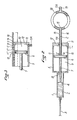
- - la figure 1 est une vue en coupe par un plan passant par l'axe longitudinal d'une seringue conforme à l'invention,
- - la figure 2 est une vue analogue à la figure 1 d'une première variante de réalisation de la même seringue,
- - la figure 3 est une vue partielle en coupe montrant une seconde variante de réalisation,
- - la figure 4 est une vue en coupe semblable aux figures 1 et 2 illustrant un exemple préféré de réalisation de l'invention.
- Les exemples décrits ici présentent tous la caractéristique générale de l'invention que l'on expliquera en premier lieu avant de montrer les variantes de détail susceptibles d'être adoptées pour les modalités pratiques de réalisation. Par conséquent, sur les figures on se servira des mêmes références pour désigner les pièces identiques ou équivalentes.
- Une seringue d'injection comprend un premier cylindre 1 ou une cartouche rapportée 1 contenant un liquide 2 à injecter par une aiguille 3 sous l'effet d'un premier piston 4 qui est en contact direct avec le liquide 2. Cette seringue comprend aussi en arrière du cylindre 1 ou de la cartouche 1, un cylindre 5 d'un vérin contenant un second piston 6 ; celui-ci est monté à une extrémité d'une tige de piston 7 qui traverse la paroi extrême 8 du côté de l'aiguille 3. ou, d'une façon plus générale, du côté de l'éjection du liquide 2 hors de la cartouche 1. L'autre extrémité de la tige de piston 7 agit directement sur le premier piston 4.
- Le second piston 6 divise le cylindre 5 du vérin en une première chambre 9 située du côté du liquide 2 à éjecter et en une seconde chambre 10 située du côté opposé. Un orifice 11 d'alimentation en fluide sous pression (de préférence un gaz comprimé) s'ouvre dans la seconde chambre 10. La position exacte de cet orifice n'a pas une grande importance du moment que la seconde chambre 10 peut être alimentée convenablement. L'orifice 11 peut être celui d'un canal 11A traversant la paroi latérale du cylindre 5, comme représenté en trait plein sur la figure 1 et en trait mixte sur la figure 2, ou traversant la paroi extrême 12 du côté opposé à l'éjection (figure 4), ou l'orifice d'un canal foré dans une tige 13 fixée au piston 6 et traversant la paroi extrême 12 comme on peut le voir sur la figure 2.
- Selon la caractéristique générale de l'invention, il existe au moins un canal de communication entre la seconde chambre 10 et l'extérieur du cylindre 5 ; ce canal a un orifice d'entrée 14 ouvert dans la seconde chambre et un orifice de sortie 15 ouvert à l'extérieur ; en outre, l'un au moins de ces deux orifices 14, 15 est situé de façon à être obturé ou dégagé à volonté par l'utilisateur pendant le déplacement d'un élément 16 monté mobile par rapport au cylindre 5-en correspondance avec les mouvements du second piston 6.
- Quand on dit que l'élément 16 est mobile en correspondance avec le piston 6, on veut dire que l'élément 16 a une course égale à celle du piston 6 et, aussi, que tout mouvement du piston 6 dans ses déplacements, en particulier dans le sens ce l'injection, accompagne un mouvement correspondant de l'élément mobile 16. De préférence, pendant la course d'injection du piston 6, le déplacement correspondant de l'élément mobile 16 a lieu dans le sens longitudinal par rapport au cylindre 5.
- Le canal de communication désigne, dans l'esprit de l'invention, tout passage, à voie unique ou à voies multiples, en un seul tronçon ou en plusieurs tronçons, qui peut exister entre la seconde chambre 10 et l'extérieur du cylindre 5.
- Dans la seringue de la figure 3, il existe de nombreux canaux de communication C, C', C", C"', etc... percés à travers la paroi latérale du cylindre 5, le long d'une même génératrice ; ils sont espacés entre eux de distances égales ou variables dont la valeur dépend de l'importance des mouvements successifs que l'on veut imposer au second piston 6. L'élément mobile 16 est monté coulissant le long du cylindre 5 de façon à recouvrir les canaux C, C', C", C"', etc...
- Plus exactement, chaque canal, C , C', C", C"', etc... a un orifice d'entrée 14 et un orifice de sortie 15, et l'élément mobile est capable de dégager puis d'obturer successivement chaque orifice 15 des canaux.
- Dans l'exemple de la figure 2, il existe un seul canal de communication C qui se confond avec une partie de la longueur du canal 11A. L'orifice d'entrée 14 du canal C est confondu avec l'orifice 11 d'alimentation de la seconde chambre 10. La tige 13 présente dans sa partie extrême un anneau 18, creux, qui constitue deux branches circulaires du canal 11 A après un embout extrême 19d'alimentation en gaz sous pression. L'orifice de sortie 15 du canal C est placé à l'intérieur de l'anneau 18 de manière à pouvoir être facilement obturé ou dégagé par le pouce de l'opérateur, introduit dans cet anneau 18 de la même façon que dans un anneau classique d'une seringue manuelle. La partie de la tige 13 située entre le cylindre 6 et l'anneau 18 constitue aussi l'élément mobile 16.
- Dans l'exemple des figures 1 et 4, le canal de communication C est composé d'un premier tronçon C1 et d'un second tronçon C2. Le premier tronçon C1 s'étend entre la seconde chambre 10 et la première chambre 9 en traversant le piston 6 et la tige de piston 7 ; le second tronçon C2 traverse la paroi du cylindre 5 entre la première chambre 9 et l'extérieur.
- Le tronçon C1 est foré coaxialement dans le piston 6 puis dans la tige de piston 7 et il se termine par une partie radiale dans cette dernière tige. Dans la seringue de la figure 1, le tronçon C1 s'ouvre dans la première chambre 9 par un orifice d'ouverture 20 situé sur la face latérale de la tige 7 ; l'élément mobile 16 traverse coaxialement la paroi extrême 12, opposée au côté de l'injection, du cylindre 5 et se termine à l'intérieur de ce dernier par une extrémité conique 21 appropriée capable d'obturer l'orifice d'entrée évasé 14 du tronçon Cl. De préférence, l'extrémité conique 21 a un diamètre supérieur à celui de la tige 16 et elle est prise entre des griffes repliées 22 qui s'étendent à partir de la face voisine du piston 6. Ces griffes laissent un jeu en sens longitudinal à l'extrémité conique 21.
- Dans la seringue de la figure 4, la tige de piston 7 est pourvue d'une extension radiale 23 dans laquelle s'étend la partie radiale du tronçon Cl ; cette extension 23 est espacée du piston 6 et le tronçon C1 se termine par un orifice d'ouverture 20 situé dans la face de l'extension 23 tournée vers le piston 6. L'élément mobile 16 traverse la paroi extrême 8, du côté de l'éjection, du cylindre 5, et se termine à l'intérieur de ce dernier par une collerette 24 montée coulissante sur la tige de piston 7 entre le piston 6 et l'extension radiale 23. La collerette 24 porte un organe d'obturation 25 capable de venir obturer l'orifice d'ouverture 20 du tronçon C1 à l'intérieur de la première chambre 9. L'élément mobile 16 traverse la paroi extrême 8 du cylindre 5, et peut glisser en sens longitudinal le long de la cartouche 1.
- Le fonctionnement est identique dans tous les cas. Quand la seringue a été mise en état d'utilisation, lorsque du gaz sous pression est envoyé par le canal d'alimentation 11A dans la seconde chambre 10, ce gaz ne peut pas avoir d'effet sur le piston 6 tant que le canal C ou un des canaux C, C', C", C"', etc... a ses deux orifices 14 et 15 ouverts, ou tant que les tronçons C1, C2 ont leurs orifices ouverts. Dès que l'on obture l'un des orifices: l'orifice 15 avec son pouce dans la seringue de la figure 2, l'orifice 15 avec l'élément mobile 16 dans la seringue de la figure 3, l'orifice 14 du tronçon C1 à l'aide de l'élément mobile 16 ou l'orifice 20 du tronçon C1 à l'aide de l'élément mobile 16 respectivement dans les seringues des figures 1 et 4, la pression monte dans la seconde chambre 10 et le piston 6 est poussé dans le sens de l'injection. Ce mouvement du piston et,donc, l'injection du liquide, s'arrête aussitôt que l'orifice du canal de communication cesse d'être obturé, ce qui se produit très rapidement si l'élément mobile 16 n'est pas poussé par l'utilisateur de manière à accompagner le piston 6.
- Avec la seringue de la figure 2, dès que l'anneau 18 entraîné par le piston 6 a avancé plus vite que le pouce qui obture l'orifice 15, l'injection s'arrête. Avec la seringue de la figure 3, si l'élément mobile 16 vient juste d'obturer l'orifice 15 du canal C', dès que le piston 6 dépasse le canal C" découvert par la fenêtre 17, l'injection s'arrête. La même chose a lieu avec les seringues des figures 1 et 4.
- Par conséquent, l'utilisateur commande lui-même la vitesse d'injection par l'intermédiaire de la vitesse à laquelle il déplace l'élément mobile 16. De plus, il constate et il sent de quelle façon lente ou rapide, le piston 6 exécute l'éjection du liquide en suivant le déplacement de l'élément mobile 16. Quand l'infiltration du liquide 2 se produit difficilement dans un'tissu osseux, l'utilisateur déplace l'élément mobile 16 lentement à une vitesse que le piston 6 peut accompagner avec régularité. Dans des tissus mous, le déplacement de l'élément mobile peut être encore plus lent, afin qu'une éjection brutale soit évitée. Ceci est important quand on songe qu'une injection d'un liquide anesthésiant faite trop rapidement peut être la cause d'incidents cardiaques et que, faite trop brutalement, elle peut provoquer des déchirements tissulaires.
- La longueur du déplacement de l'élément mobile 16 est la même que celle des pistons 6 et 4 ; elle est proportionnelle à la quantité de liquide éjecté. Par conséquent, la course que l'utilisateur fait accomplir à l'élément mobile 16 le renseigne sur la fraction correspondante de liquide éjecté. Il peut donc accélérer ou ralentir en conséquence le mouvement de l'élément mobile 16 ou même l'interrompre pour ne faire qu'une injection partielle dans certaines circonstances. Le mouvement peut être aussi lent qu'il le faut pour que le dosage soit précis ; de plus, l'élément mobile 16 peut porter une graduation.
- Bien entendu, comme avec toutes les seringues à injection assistées par un vérin, la force ou la fatigue de l'utilisateur n'interviennent plus pour limiter les injections, même dans les tissus résistants.
- Avec une seringue conforme à l'invention, le piston se déplace à une vitesse aussi lente que l'utilisateur le veut, sur la totalité de sa course. Cela n'empêche pas, à l'inverse, la possibilité d'éjectionstrès brutalescar il est facile à l'utilisateur de pousser l'élément mobile 16 à la vitesse la plus grande que peut prendre le piston. Par conséquent des infiltrations sans aiguille sont possibles aussi avec la seringue de l'invention.
- Les seringues des figures 1 à 3 sont relativement longues puisque la longueur de l'élément mobile 16 s'a- . joute, au début de l'éjection, à celle des cylindres 1 et 5. La seringue de la figure 4 est plus courte ; elle est préférable pour les soins dentaires. Dans ce cas, l'élément mobile 16 est déplacé vers l'aiguille, pendant les injections, à l'aide d'un doigt comme l'index.
- On notera que la première chambre 9 a un volume décroissant pendant une course d'éjection ; il est nécessaire qu'elle communique toujours librement avec l'atmosphère. Il n'est pas prévu, selon l'invention, que cette chambre 9 soit remplie de gaz sous pression afin d'équilibrer la pression exercée sur le piston 6 dans la seconde chambre 10. En conséquence, quand la résistance des tissus est faible, le piston 6 est poussé par le gaz sous pression quand l'orifice du canal de communication n'est encore que partiellement obturé. Une obturation totale n'est nécessaire que lorsque la résistance des tissus est forte. Il en résulte que, avec une seringue conforme à l'invention, la force mise en jeu est juste celle qui est nécessaire et la consommation de gaz sous pression est dosée économiquement en fonction des besoins.
- Dans une seringue réalisée comme décrit en référence à la figure 4, le piston 6 avait un diamètre de 26 mm et l'orifice 20 un diamètre de 0,3 mm pour une pression du gaz d'alimentation de 4 bars.
- La seringue de l'invention est utilisable pour l'injection de liquides d'anesthésie ainsi qu'on l'a dit plus haut mais il est clair qu'elle n'est pas limitée à cet usage, en raison précisément de son aptitude à créer, sous le contrôle précis et dosé de l'opérateur, une force importante d'éjection puisque l'énergie est fournie par une source extérieure. En particulier, les dentistes se servent main-' tenant pour la prise des empreintes dentaires d'une pâte visqueuse que l'on prépare au moment de l'emploi par le mélange d'un premier composant à base de silicone et d'un second composant contenant un durcisseur. Après préparation, cette pâte est introduite dans une seringue et éjectée à l'aide de celle-ci contre les dents et les gencives dont on veut relever l'empreinte. La seringue de l'invention convient parfaitement à cet usage.
- Dans les exemples de réalisation décrits plus haut on s'est référé au cas d'une seringue servant uniquement à produire l'éjection d'un liquide ou d'une pâte par suite du déplacement asservi du piston dans le sens désirable. On ne sortirait pas du cadre de l'invention en prévoyant le déplacement asservi du piston dans le sens d'une aspiration si l'on voulait, par exemple, produire une succion forte ou brusque à l'extrémité d'un conduit monté sur le corps de la seringue. Il suffit dans ce cas de prévoir une simple inversion de la disposition des organes décrits, notamment le sens de l'arrivée et de la sortie du fluide sous pression et du déplacement de l'élément mobile commandant le débit de ce fluide.
Claims (8)
Applications Claiming Priority (2)
| Application Number | Priority Date | Filing Date | Title |
|---|---|---|---|
| FR7927275 | 1979-11-06 | ||
| FR7927275A FR2468377A1 (fr) | 1979-11-06 | 1979-11-06 | Seringue a fonctionnement assiste par une source exterieure d'energie |
Publications (3)
| Publication Number | Publication Date |
|---|---|
| EP0028557A2 true EP0028557A2 (fr) | 1981-05-13 |
| EP0028557A3 EP0028557A3 (en) | 1981-06-17 |
| EP0028557B1 EP0028557B1 (fr) | 1985-04-10 |
Family
ID=9231313
Family Applications (1)
| Application Number | Title | Priority Date | Filing Date |
|---|---|---|---|
| EP80401510A Expired EP0028557B1 (fr) | 1979-11-06 | 1980-10-23 | Seringue d'injection |
Country Status (6)
| Country | Link |
|---|---|
| US (1) | US4323066A (fr) |
| EP (1) | EP0028557B1 (fr) |
| JP (1) | JPS5676957A (fr) |
| CA (1) | CA1136942A (fr) |
| DE (1) | DE3070466D1 (fr) |
| FR (1) | FR2468377A1 (fr) |
Cited By (5)
| Publication number | Priority date | Publication date | Assignee | Title |
|---|---|---|---|---|
| DE3244791A1 (de) * | 1982-12-03 | 1984-07-05 | Willy 2000 Hamburg Kühn | Verfahren und vorrichtung zum injizieren von injektionsmitteln |
| US10493199B2 (en) | 2006-03-30 | 2019-12-03 | Valeritas, Inc. | Multi-cartridge fluid delivery device |
| US10525194B2 (en) | 2003-04-23 | 2020-01-07 | Valeritas, Inc. | Hydraulically actuated pump for fluid administration |
| EP2968732B1 (fr) * | 2013-03-14 | 2021-01-06 | Bayer Healthcare LLC | Système d'administration de fluide ayant entrainement de vacuum |
| US10933188B2 (en) | 2009-10-13 | 2021-03-02 | Zealand Pharma A/S | Fluid delivery device |
Families Citing this family (37)
| Publication number | Priority date | Publication date | Assignee | Title |
|---|---|---|---|---|
| USRE35979E (en) * | 1984-06-06 | 1998-12-01 | Mtfp, Inc. | Angiographic injector and angiographic syringe for use therewith |
| AT382388B (de) * | 1985-03-08 | 1987-02-25 | Voest Alpine Ag | Vorrichtung zur vergasung von brennstoffen |
| US4703763A (en) * | 1985-06-17 | 1987-11-03 | Sherwood Medical Company | Blood sample syringe |
| US4636198A (en) * | 1985-11-18 | 1987-01-13 | Mallinckrodt, Inc. | Power syringe with volume reducing adapter |
| US5180371A (en) * | 1986-05-30 | 1993-01-19 | Spintech, Inc. | Hypodermic anesthetic injection apparatus and method |
| US4747824A (en) * | 1986-05-30 | 1988-05-31 | Spinello Ronald P | Hypodermic anesthetic injection method |
| US4711250A (en) * | 1986-09-09 | 1987-12-08 | Gilbaugh Jr James H | Hand-held medical syringe actuator device |
| DE3851762T2 (de) * | 1988-05-16 | 1995-05-11 | Spintech Inc | Hypodermisches ansaug-einspritzgerät. |
| AU646793B2 (en) * | 1988-05-25 | 1994-03-10 | Milestone Scientific, Inc. | Aspirating hypodermic syringe apparatus and method |
| JPH0452465A (ja) * | 1990-06-18 | 1992-02-20 | Daikin Ind Ltd | 冷凍装置の運転制御装置 |
| JPH085715Y2 (ja) * | 1990-10-31 | 1996-02-21 | 正成 中山 | 注射器用吸引力増強具 |
| US5354273A (en) * | 1992-12-14 | 1994-10-11 | Mallinckrodt Medical, Inc. | Delivery apparatus with pressure controlled delivery |
| US5373684A (en) * | 1992-12-14 | 1994-12-20 | Mallinckrodt Medical, Inc. | Process and apparatus used in producing prefilled, sterile delivery devices |
| JP3639095B2 (ja) * | 1997-09-10 | 2005-04-13 | 株式会社根本杏林堂 | 塵埃防止型シリンジ |
| NZ337318A (en) * | 1999-08-18 | 2002-07-26 | Interag | Dispensing apparatus for dispensing same or different materials for at least two reservoirs |
| US6425885B1 (en) * | 1999-12-20 | 2002-07-30 | Ultradent Products, Inc. | Hydraulic syringe |
| US20030105433A1 (en) * | 2001-11-30 | 2003-06-05 | Ruben Philip H. | Disposable syringe and cartridge with pneumatic chamber |
| US6997910B2 (en) * | 2004-05-03 | 2006-02-14 | Infusive Technologies, Llc | Multi-chamber, sequential dose dispensing syringe |
| US7998106B2 (en) * | 2004-05-03 | 2011-08-16 | Thorne Jr Gale H | Safety dispensing system for hazardous substances |
| US9656028B2 (en) | 2006-03-07 | 2017-05-23 | Leibovici Llc | Method and apparatus for applying an anesthetic and batericide |
| US10675417B2 (en) | 2006-03-07 | 2020-06-09 | Leibovici, Llc | Method and apparatus for applying an anesthetic and bactericide |
| US10004855B2 (en) | 2006-03-07 | 2018-06-26 | Leibovici Llc | Method and apparatus for applying an anesthetic and bactericide |
| US20090187135A1 (en) * | 2008-01-18 | 2009-07-23 | Eilaz Babaev | Ultrasonic syringe |
| WO2011022618A1 (fr) | 2009-08-21 | 2011-02-24 | Becton Dickinson France Sas | Fiole active pré-remplie dotée d'un ensemble poussoir intégré |
| US9101713B2 (en) * | 2013-03-12 | 2015-08-11 | Bayer Medical Care Inc. | Constant force syringe |
| US9913777B2 (en) | 2013-05-16 | 2018-03-13 | Sandy Wengreen | Storage systems and methods for medicines |
| US10588820B2 (en) | 2013-05-16 | 2020-03-17 | Sandy Wengreen | Storage systems and methods for medicines |
| US20140343493A1 (en) * | 2013-05-16 | 2014-11-20 | Sandy Wengreen | Storage devices and storage methods for injectable substances |
| US9877894B2 (en) | 2013-05-16 | 2018-01-30 | Sandy Wengreen | Storage systems and methods for medicines |
| US9707156B2 (en) | 2013-05-16 | 2017-07-18 | Sandy Wengreen | Storage systems and methods for medicines |
| WO2015009673A2 (fr) | 2013-07-17 | 2015-01-22 | Bayer Medical Care Inc. | Dispositif de perfusion dans le trou à base de cartouche |
| USD804807S1 (en) | 2016-09-22 | 2017-12-12 | Sandy Wengreen | Insulated container |
| CN108827709B (zh) * | 2018-06-20 | 2020-11-06 | 江苏嘉宇特种装备股份有限公司 | 一种用于反应釜的取样装置 |
| US20210353868A1 (en) * | 2018-09-13 | 2021-11-18 | Cedars-Sinai Medical Center | Hydraulic syringe |
| CN113677382B (zh) * | 2019-04-09 | 2023-06-09 | 西医药服务以色列有限公司 | 具有集成式注射器的液体输送装置 |
| KR102309710B1 (ko) * | 2021-04-20 | 2021-10-08 | 주식회사 테라젝아시아 | 주사기형 마이크로니들 |
| CN113304377B (zh) * | 2021-04-25 | 2023-07-04 | 山东大学齐鲁医院 | 一种麻醉用注射器 |
Family Cites Families (7)
| Publication number | Priority date | Publication date | Assignee | Title |
|---|---|---|---|---|
| GB191016647A (en) * | 1910-07-12 | 1911-07-06 | Dental Mfg Co Ltd | Improvements in and relating to Hypodermic Syringes. |
| US3279659A (en) * | 1965-03-02 | 1966-10-18 | Prec Sampling Corp | Injection apparatus |
| US3306502A (en) * | 1965-04-28 | 1967-02-28 | Prec Sampling Corp | Apparatus for injection of fluids |
| US3605746A (en) * | 1969-12-10 | 1971-09-20 | Kendall & Co | Diapering of infants |
| US3605745A (en) * | 1969-12-15 | 1971-09-20 | Milton Hodosh | Dental injection apparatus |
| FR2193626A1 (en) | 1972-07-27 | 1974-02-22 | Air Liquide | Injection process for medicaments - using gas-operated sec. piston, for easy press. regulation |
| US3818907A (en) * | 1973-04-23 | 1974-06-25 | M Walton | Double cylinder lavage syringe |
-
1979
- 1979-11-06 FR FR7927275A patent/FR2468377A1/fr active Granted
-
1980
- 1980-09-24 US US06/190,259 patent/US4323066A/en not_active Expired - Lifetime
- 1980-10-01 CA CA000361317A patent/CA1136942A/fr not_active Expired
- 1980-10-23 EP EP80401510A patent/EP0028557B1/fr not_active Expired
- 1980-10-23 DE DE8080401510T patent/DE3070466D1/de not_active Expired
- 1980-10-29 JP JP15085280A patent/JPS5676957A/ja active Granted
Cited By (7)
| Publication number | Priority date | Publication date | Assignee | Title |
|---|---|---|---|---|
| DE3244791A1 (de) * | 1982-12-03 | 1984-07-05 | Willy 2000 Hamburg Kühn | Verfahren und vorrichtung zum injizieren von injektionsmitteln |
| US10525194B2 (en) | 2003-04-23 | 2020-01-07 | Valeritas, Inc. | Hydraulically actuated pump for fluid administration |
| US11642456B2 (en) | 2003-04-23 | 2023-05-09 | Mannkind Corporation | Hydraulically actuated pump for fluid administration |
| US10493199B2 (en) | 2006-03-30 | 2019-12-03 | Valeritas, Inc. | Multi-cartridge fluid delivery device |
| US10933188B2 (en) | 2009-10-13 | 2021-03-02 | Zealand Pharma A/S | Fluid delivery device |
| USD1011511S1 (en) | 2009-10-13 | 2024-01-16 | Mannkind Corporation | Fluid delivery device |
| EP2968732B1 (fr) * | 2013-03-14 | 2021-01-06 | Bayer Healthcare LLC | Système d'administration de fluide ayant entrainement de vacuum |
Also Published As
| Publication number | Publication date |
|---|---|
| FR2468377A1 (fr) | 1981-05-08 |
| EP0028557A3 (en) | 1981-06-17 |
| EP0028557B1 (fr) | 1985-04-10 |
| CA1136942A (fr) | 1982-12-07 |
| JPS5676957A (en) | 1981-06-24 |
| US4323066A (en) | 1982-04-06 |
| JPS5650981B2 (fr) | 1981-12-02 |
| FR2468377B1 (fr) | 1983-12-16 |
| DE3070466D1 (en) | 1985-05-15 |
Similar Documents
| Publication | Publication Date | Title |
|---|---|---|
| EP0028557B1 (fr) | Seringue d'injection | |
| EP0294272B1 (fr) | Appareil d'injection de liquide, sans aiguille notamment à usage de soins dentaires | |
| BE1001046A4 (fr) | Dispositif de perfusion. | |
| EP0186232A1 (fr) | Seringue | |
| EP0956062B1 (fr) | Injecteur medical | |
| EP0538200A1 (fr) | Appareil d'obturation par le vide de canaux radiculaires dentaires | |
| FR3072313B1 (fr) | Dispositif de distribution de produit fluide | |
| EP4132633A1 (fr) | Module de marquage pour un appareil destiné à l'application d'un produit colorant et appareil utilisant un tel module de marquage | |
| EP0986411B1 (fr) | Seringue d'injection perfectionnee, comportant des moyens d'aspiration | |
| BE634108A (fr) | ||
| FR2629706A1 (fr) | Appareil d'injection de liquide, notamment a usage de soins dentaires | |
| FR2748394A1 (fr) | Applicateur de medicaments pour animaux | |
| CH618872A5 (en) | Surgical instrument for the preparation and injection of a bone cement | |
| CH570169A5 (en) | Rear filling liq syringe distributor - with filling device | |
| WO1999044658A1 (fr) | Dispositif pour l'injection sous-cutanee sans aiguille d'un medicament sous forme liquide | |
| EP0626830B1 (fr) | Dispositif d'application de matiere d'obturation dans une cavite dentaire | |
| FR2644056A1 (fr) | Pince a clamper (chirurgicale) | |
| WO2021123615A1 (fr) | Dispositif de distribution de produit fluide | |
| FR2540385A1 (fr) | Injecteur d'anesthesie intradiploique | |
| CA2605997A1 (fr) | Dispositif d'application d'un fluide sur une zone a traiter comprenant une minuterie | |
| FR2649616A1 (fr) | Seringue et aiguille d'injection a usage unique | |
| EP3752230B1 (fr) | Tete d'injection d'une substance fluide permettant le controle du site d'injection avant injection de la substance fluide et seringue comprenant une telle tete | |
| FR2474319A1 (fr) | Dispositif d'injection sans aiguille de substances medicamenteuses liquides | |
| BE1006260A6 (fr) | Seringue a usage medical unique, autodestructive et a retrait d'aiguille automatique. | |
| FR2583631A1 (fr) | Appareil pour la distribution et la mise en place d'amalgame dentaire |
Legal Events
| Date | Code | Title | Description |
|---|---|---|---|
| PUAI | Public reference made under article 153(3) epc to a published international application that has entered the european phase |
Free format text: ORIGINAL CODE: 0009012 |
|
| PUAL | Search report despatched |
Free format text: ORIGINAL CODE: 0009013 |
|
| AK | Designated contracting states |
Designated state(s): DE GB IT |
|
| 17P | Request for examination filed |
Effective date: 19810401 |
|
| AK | Designated contracting states |
Designated state(s): DE GB IT |
|
| GRAA | (expected) grant |
Free format text: ORIGINAL CODE: 0009210 |
|
| AK | Designated contracting states |
Designated state(s): DE GB IT |
|
| PG25 | Lapsed in a contracting state [announced via postgrant information from national office to epo] |
Ref country code: IT Free format text: LAPSE BECAUSE OF FAILURE TO SUBMIT A TRANSLATION OF THE DESCRIPTION OR TO PAY THE FEE WITHIN THE PRESCRIBED TIME-LIMIT;WARNING: LAPSES OF ITALIAN PATENTS WITH EFFECTIVE DATE BEFORE 2007 MAY HAVE OCCURRED AT ANY TIME BEFORE 2007. THE CORRECT EFFECTIVE DATE MAY BE DIFFERENT FROM THE ONE RECORDED. Effective date: 19850410 |
|
| REF | Corresponds to: |
Ref document number: 3070466 Country of ref document: DE Date of ref document: 19850515 |
|
| PG25 | Lapsed in a contracting state [announced via postgrant information from national office to epo] |
Ref country code: DE Effective date: 19850701 |
|
| PLBE | No opposition filed within time limit |
Free format text: ORIGINAL CODE: 0009261 |
|
| STAA | Information on the status of an ep patent application or granted ep patent |
Free format text: STATUS: NO OPPOSITION FILED WITHIN TIME LIMIT |
|
| 26N | No opposition filed | ||
| GBPC | Gb: european patent ceased through non-payment of renewal fee | ||
| PG25 | Lapsed in a contracting state [announced via postgrant information from national office to epo] |
Ref country code: GB Effective date: 19881118 |