EP0028588A1 - Poinçonneuse automatique - Google Patents
Poinçonneuse automatique Download PDFInfo
- Publication number
- EP0028588A1 EP0028588A1 EP80830069A EP80830069A EP0028588A1 EP 0028588 A1 EP0028588 A1 EP 0028588A1 EP 80830069 A EP80830069 A EP 80830069A EP 80830069 A EP80830069 A EP 80830069A EP 0028588 A1 EP0028588 A1 EP 0028588A1
- Authority
- EP
- European Patent Office
- Prior art keywords
- punching
- metal sheet
- punch
- arm
- fact
- Prior art date
- Legal status (The legal status is an assumption and is not a legal conclusion. Google has not performed a legal analysis and makes no representation as to the accuracy of the status listed.)
- Granted
Links
- 238000004080 punching Methods 0.000 title claims abstract description 80
- 239000002184 metal Substances 0.000 claims abstract description 38
- 238000006073 displacement reaction Methods 0.000 claims description 11
- 238000000034 method Methods 0.000 claims description 4
- 238000003780 insertion Methods 0.000 claims description 3
- 230000037431 insertion Effects 0.000 claims description 3
- 210000000080 chela (arthropods) Anatomy 0.000 description 7
- 230000000694 effects Effects 0.000 description 5
- 239000000969 carrier Substances 0.000 description 2
- 238000006467 substitution reaction Methods 0.000 description 2
- 230000015572 biosynthetic process Effects 0.000 description 1
- 238000005755 formation reaction Methods 0.000 description 1
- 230000000717 retained effect Effects 0.000 description 1
- 238000005096 rolling process Methods 0.000 description 1
- 230000003245 working effect Effects 0.000 description 1
Images





Classifications
-
- B—PERFORMING OPERATIONS; TRANSPORTING
- B21—MECHANICAL METAL-WORKING WITHOUT ESSENTIALLY REMOVING MATERIAL; PUNCHING METAL
- B21D—WORKING OR PROCESSING OF SHEET METAL OR METAL TUBES, RODS OR PROFILES WITHOUT ESSENTIALLY REMOVING MATERIAL; PUNCHING METAL
- B21D28/00—Shaping by press-cutting; Perforating
- B21D28/24—Perforating, i.e. punching holes
- B21D28/246—Selection of punches
-
- B—PERFORMING OPERATIONS; TRANSPORTING
- B21—MECHANICAL METAL-WORKING WITHOUT ESSENTIALLY REMOVING MATERIAL; PUNCHING METAL
- B21D—WORKING OR PROCESSING OF SHEET METAL OR METAL TUBES, RODS OR PROFILES WITHOUT ESSENTIALLY REMOVING MATERIAL; PUNCHING METAL
- B21D28/00—Shaping by press-cutting; Perforating
- B21D28/02—Punching blanks or articles with or without obtaining scrap; Notching
- B21D28/04—Centering the work; Positioning the tools
-
- B—PERFORMING OPERATIONS; TRANSPORTING
- B21—MECHANICAL METAL-WORKING WITHOUT ESSENTIALLY REMOVING MATERIAL; PUNCHING METAL
- B21D—WORKING OR PROCESSING OF SHEET METAL OR METAL TUBES, RODS OR PROFILES WITHOUT ESSENTIALLY REMOVING MATERIAL; PUNCHING METAL
- B21D28/00—Shaping by press-cutting; Perforating
- B21D28/24—Perforating, i.e. punching holes
- B21D28/26—Perforating, i.e. punching holes in sheets or flat parts
-
- B—PERFORMING OPERATIONS; TRANSPORTING
- B21—MECHANICAL METAL-WORKING WITHOUT ESSENTIALLY REMOVING MATERIAL; PUNCHING METAL
- B21D—WORKING OR PROCESSING OF SHEET METAL OR METAL TUBES, RODS OR PROFILES WITHOUT ESSENTIALLY REMOVING MATERIAL; PUNCHING METAL
- B21D43/00—Feeding, positioning or storing devices combined with, or arranged in, or specially adapted for use in connection with, apparatus for working or processing sheet metal, metal tubes or metal profiles; Associations therewith of cutting devices
- B21D43/003—Positioning devices
-
- Y—GENERAL TAGGING OF NEW TECHNOLOGICAL DEVELOPMENTS; GENERAL TAGGING OF CROSS-SECTIONAL TECHNOLOGIES SPANNING OVER SEVERAL SECTIONS OF THE IPC; TECHNICAL SUBJECTS COVERED BY FORMER USPC CROSS-REFERENCE ART COLLECTIONS [XRACs] AND DIGESTS
- Y10—TECHNICAL SUBJECTS COVERED BY FORMER USPC
- Y10T—TECHNICAL SUBJECTS COVERED BY FORMER US CLASSIFICATION
- Y10T83/00—Cutting
- Y10T83/04—Processes
- Y10T83/0505—With reorientation of work between cuts
- Y10T83/051—Relative to same tool
-
- Y—GENERAL TAGGING OF NEW TECHNOLOGICAL DEVELOPMENTS; GENERAL TAGGING OF CROSS-SECTIONAL TECHNOLOGIES SPANNING OVER SEVERAL SECTIONS OF THE IPC; TECHNICAL SUBJECTS COVERED BY FORMER USPC CROSS-REFERENCE ART COLLECTIONS [XRACs] AND DIGESTS
- Y10—TECHNICAL SUBJECTS COVERED BY FORMER USPC
- Y10T—TECHNICAL SUBJECTS COVERED BY FORMER US CLASSIFICATION
- Y10T83/00—Cutting
- Y10T83/162—With control means responsive to replaceable or selectable information program
-
- Y—GENERAL TAGGING OF NEW TECHNOLOGICAL DEVELOPMENTS; GENERAL TAGGING OF CROSS-SECTIONAL TECHNOLOGIES SPANNING OVER SEVERAL SECTIONS OF THE IPC; TECHNICAL SUBJECTS COVERED BY FORMER USPC CROSS-REFERENCE ART COLLECTIONS [XRACs] AND DIGESTS
- Y10—TECHNICAL SUBJECTS COVERED BY FORMER USPC
- Y10T—TECHNICAL SUBJECTS COVERED BY FORMER US CLASSIFICATION
- Y10T83/00—Cutting
- Y10T83/647—With means to convey work relative to tool station
- Y10T83/654—With work-constraining means on work conveyor [i.e., "work-carrier"]
- Y10T83/6563—With means to orient or position work carrier relative to tool station
-
- Y—GENERAL TAGGING OF NEW TECHNOLOGICAL DEVELOPMENTS; GENERAL TAGGING OF CROSS-SECTIONAL TECHNOLOGIES SPANNING OVER SEVERAL SECTIONS OF THE IPC; TECHNICAL SUBJECTS COVERED BY FORMER USPC CROSS-REFERENCE ART COLLECTIONS [XRACs] AND DIGESTS
- Y10—TECHNICAL SUBJECTS COVERED BY FORMER USPC
- Y10T—TECHNICAL SUBJECTS COVERED BY FORMER US CLASSIFICATION
- Y10T83/00—Cutting
- Y10T83/647—With means to convey work relative to tool station
- Y10T83/6572—With additional mans to engage work and orient it relative to tool station
-
- Y—GENERAL TAGGING OF NEW TECHNOLOGICAL DEVELOPMENTS; GENERAL TAGGING OF CROSS-SECTIONAL TECHNOLOGIES SPANNING OVER SEVERAL SECTIONS OF THE IPC; TECHNICAL SUBJECTS COVERED BY FORMER USPC CROSS-REFERENCE ART COLLECTIONS [XRACs] AND DIGESTS
- Y10—TECHNICAL SUBJECTS COVERED BY FORMER USPC
- Y10T—TECHNICAL SUBJECTS COVERED BY FORMER US CLASSIFICATION
- Y10T83/00—Cutting
- Y10T83/808—Two tool pairs, driver for one pair moves relative to driver for other pair
- Y10T83/825—Successively acting
-
- Y—GENERAL TAGGING OF NEW TECHNOLOGICAL DEVELOPMENTS; GENERAL TAGGING OF CROSS-SECTIONAL TECHNOLOGIES SPANNING OVER SEVERAL SECTIONS OF THE IPC; TECHNICAL SUBJECTS COVERED BY FORMER USPC CROSS-REFERENCE ART COLLECTIONS [XRACs] AND DIGESTS
- Y10—TECHNICAL SUBJECTS COVERED BY FORMER USPC
- Y10T—TECHNICAL SUBJECTS COVERED BY FORMER US CLASSIFICATION
- Y10T83/00—Cutting
- Y10T83/889—Tool with either work holder or means to hold work supply
Definitions
- the present invention relates to an automatic punching machine, particularly one suitable for performing punch ing of a metal sheet in a programmed and programmable manner according to a predetermined number of different punching shapes.
- the punching machine of this invention is of the type comprising a punching head provided with a plurality of punch/die pairs for effecting the desired punching of a metal sheet, and a numerically controlled programmable manipulator, equipped with gripping means for the said metal sheet, for displacing it over a horizontal plane passing between the said punches and their associated dies.
- This mode of operation which is tied to the structural and functional characteristics of the known punching machine and, above all, to the fundamental characteristic of the existence of a single and unchangeable oper ative position, involves dead times which until now were inevitable, for the substitution of the punch/die pair in the operative position, as well as a not inconsiderable consumption of time tied to the movements which the manipulator must perform in order to displace a metal sheet during the operation of successive punch/ die pairs.
- the technical problem on which this invention is based is, consequently, that of making available an automatic punching machine having structural and functional cha- ractertistics such as to eliminate the said dead times and to reduce substantially the consumption of time involved in the displacement of the manipulator.
- the said operating head includes two essentially parallelepiped superimposed blocks spaced from one another by a distance such as to allow the insertion between them and the displacement of a metal sheet to be punched, a plurality of seats formed in each of the said blocks, each seat of a block being coaxial with a corresponding seat of the other block thus forming a pair of seats for receiving a respective punch/die pair, the axis of each of the said pairs of seats constituting one of the said plurality of the said operative positions.
- At least a part of the said pair of coaxial seats is formed in respective carriers insertable in and removable from the said blocks of the punching head.
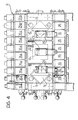
- a punching machine 1 With reference to Figures 1 and 2, there is generally indicated a punching machine 1 according to the invention, the support structure of which is indicated 2 and is fixed to the base with conventional means 3.
- the support structure 2 has a very-deep C-shape, with upper 4 and lower 5 horizontal arms.
- the punching head 6 comprises two superimposed paralle lepiped blocks 8, 9 spaced from one another by a predetermined distance so as to form a horizontal passage 10 able to allow the insertion and all the displacements in a horizontal plane of a metal sheet to be subjected to punching.
- the said passage 10 therefore constitutes the working region of the punching machine of this invention.
- a median longitudinal portion of the block 8 there are formed seats 11, 12 and 13 in which are positioned, and movably guided, respective punches 14, 15 and 16. Whilst the punch 14 is utilised to effect deformations (recesses) of predetermined shape, the punches 15 and 16 are utilised to effect different formations of the edges of a metal sheet.
- the punch 15 constitutes the movable cylindrical body of a vertical axis double acting hydraulic piston/cylinder unit.
- the fixed stem 17 of the said unit which is rigidly connected to the block 8 through an associated plate 18, forms with the punch 15 two chambers 19, 20 to each of which leads a respective oil duct 21, 22.
- the flows of oil in the said ducts for the vertical movement of the punch 15 are controlled by a conventional solenoid valve 23.
- the punches 14 and 16 are constructed and con trolled in an entirely similar manner to the said punch 15, and for this reason are not described in detail.
- the solenoid valves associated with the said punches 14 and 16 are indicated 24 and 25.
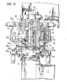
- each of the said seats 26 there is located a vertical axis double acting hydraulic piston / cylinder unit comprising a cylindri cal guide bush 28, a stem 29, a piston 30-and two cham bers 31, 32 to which lead respective oil ducts 33,34.
- the flow of oil in these ducts is controlled by solenoid valve 35 (35a) preferably mounted on the block 8.
- a recessed seat 36 (36a) in which is engaged a punch 37 (37a) which extends through a small block 38 (38a) which serves as a guide for the punch itself.
- the plurality of guide blocks 38 (38a) with their associated punches 37 (37a) slidable within them, are mounted and fixed in carriers 39 (39a) in their turn removably mounted and fixed with conventional means (not shown) to the block 8.
- the block 9 which is fixed with conventional means (not shown) to the lower arm 5 of the support structure 2, there are formed seats with vertical axes for receiving associated movably guided dies.
- Each of these seats is coaxial with a corresponding seat formed in the block 8 and each die obviously has a corresponding form to that of the associated punch to effect, when required, the desired punching of a metal sheet.
- the seats and the associated dies of the block 9 are indicated with the same reference numerals as the corresponding seats and punches of the block 8 but increased by 100.
- each punch/die pair is operable independently from the others.
- the manipulator 7 is essentially constituted by two arms 40, 41 extending along and movable in directions perpendicular from one another.
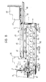
- the arm 40 extends centrally and longitudinally with respect to the arms 4 and 5 of the support structure 2 and is supported by means of, for example, the engagement of a plurality of pairs of wheels, schematically indicated 42 and 43 ( Figures 8,9) with rectilinear rails 44 fixedly supported on the structure 2.
- a rack 45 is utilised for the movement of the arm 40, this rack being longitudinally fixed to the top of the arm itself and being in engagement with a first pinion 46, driven by an hydraulic motor 47, and with a second pinion 48 driven by a dc electric motor 49.
- the motors 47, 49 are supported in fixed positions by the support structure 2.
- the motors 47, 49 co-operate both in the rapid displacement of the arm 40 and in braking it, as well as in taking up the play between the teeth of the rack and of the pinions mentioned above.
- the arm 41 is mounted transversely on the arm 40 close to its end facing the punching head 6, and is movably guided in a direction perpendicular to the direction of displacement of the arm 40.
- the arm 41 ( Figure 7) there are formed two longitudinal ly extending channels 50 and 50a with which two-pluralities of wheels 51, 51a are in rolling engagement, these wheels being supported freely by the arm 40.
- a third plurality of free wheels 52 completes the desired support of the arm 41.
- the arm 41 On the side opposite the rack 53, the arm 41 is equipped with a plurality of pincers 58 and associated operating means 59 for gripping a metal sheet along one edge thereof.
- a support plane for receiving and supporting a metal sheet to be subjected to punching operations is generally indicated 60.
- This support plane is constituted by a plurality of cylindrical rods all indicated 61, extending parallel to the arm 41 of the manipulator.
- Each rod 61 is mounted eccentrically on a pivot pin 62 and is provided with a rod-like projection 63 at the free end of which there is mounted a free wheel 64.
- One (or more) rectilinear shaft, indicated 65, is rigidly supported by the arm 40 of the manipulator 7 and extends beneath and parallel to it.
- the rectilinearity of the said shaft 65 during alternate displacements of the arm 40 is ensured by a plurality of appropriate supports 65a.
- the free end of the shaft 65 is tapered towards the punching head 6.
- the dimensional characteristics of the shaft 65 and its position are predetermined in such a way that, during advancing movement of the arm 40 towards the punching head 6 its tapered free end comes into contact with the wheels 64 of the rods 61 as is shown in Figures 8 and 9. It is to be noted that the said tapered free end of the shaft 65 projects by a predetermined distance in front of the plurality of pincers 58 with which the arm 41 of the manipulator 7 is equipped.
- the shaft 65 When the manipulator 7 is fully retracted, that is to say in the position spaced furthest from the punching head 6, the shaft 65 does not interfere with the rods 61 which, because of the eccentricity and of the action of resilient means, not shown, assume a raised position. In this position the upper generatrices of all the rods 61 lie in a single horizontal plane indicated by the dot and dash line in Figure 9, which coincides with the wor king plane of the block 9 of the punching head 6 and which constitutes the plane for receiving and supporting a metal sheet to be subjected to punching. Gradually as the manipulator advances towards the operating head the shaft 65 causes a lowering of the rods 61. The plane defined by the rods 61 is substantially a progressively disappearing plane.
- the punching machine of this invention is equipped with a rotator 66, positioned laterally of the punching head 6 to rotate the metal sheet by 90 or 180 in one direction or the other.
- the said rotator 66 is of the type illustrated and described in D O S No. 28 39 978.2 filed on September 14, 1978 in the name of the same Applicant and mentioned for reference purposes.
- the punching of a metal sheet is performed in accordance with the following method.
- the punching machine is pre-arranged to receive a metal sheet L.
- the manipulator 7 is retracted sufficiently, with respect to the punching head 6, and the arm 41 of the manipulator is sufficiently displaced laterally in such a way that all the pincers 58 with which it is equipped are laterally displaced with respect to the head 6.
- this position of the arm 41 of the manipulator is indicated with a dot and dash line. Because the manipulator 7 is in the said positron, the rollers 61 are in the "raised" position constituting the plane for receiving and supporting the said metal sheet L.
- the metal sheet L is carried onto the said support plane, arriving in position from one side of the punching head 6, for example by means of a conventional conveyor indicated 67.
- the positioning of the said sheet L is such that its longitudinal median line coincides with the longitudinal median line of the punching head 6,indicated 6a in Figure 3.
- the manipulator 7 is made to advance until the pincers 58 of the arm 41 can press the sheet against suitable references, not shown since they are conventional, and then grip the edge of the metal sheet.
- the manipulator 7 by means of suitable and exact displacements of its arms 40 and 41, controlled by means of a process computer on the basis of a predetermined programme, provides for subsequent positioning of the metal sheet L between the blocks 8, 9 of the punching head 6 to that on the half thereof opposite the edge gripped by the pincers 58 all the dif ferent and predetermined punching can be successively performed.
- the system for controlling the di splacements of the arms 40 and 41 of the manipulator must take account both of the co-ordinates of the points of the metal sheet in which the different punching is to be performed, and of the co-ordinates of the associated punches.
- the said sheet is taken by the rotator 66, released from the pincers 58, rotated through 180°, gripped again by the pincers 58 and taken back to the working region of the manipulator 7 where the desired different punching on the second half of the sheet itself is effected.
Landscapes
- Engineering & Computer Science (AREA)
- Mechanical Engineering (AREA)
- Perforating, Stamping-Out Or Severing By Means Other Than Cutting (AREA)
- Punching Or Piercing (AREA)
- Processing Of Stones Or Stones Resemblance Materials (AREA)
Priority Applications (1)
| Application Number | Priority Date | Filing Date | Title |
|---|---|---|---|
| AT80830069T ATE6747T1 (de) | 1979-09-12 | 1980-09-08 | Automatische stanzmaschine. |
Applications Claiming Priority (2)
| Application Number | Priority Date | Filing Date | Title |
|---|---|---|---|
| IT25676/79A IT1123708B (it) | 1979-09-12 | 1979-09-12 | Macchina punzonatrice automatica |
| IT2567679 | 1979-09-12 |
Publications (3)
| Publication Number | Publication Date |
|---|---|
| EP0028588A1 true EP0028588A1 (fr) | 1981-05-13 |
| EP0028588B1 EP0028588B1 (fr) | 1984-03-21 |
| EP0028588B2 EP0028588B2 (fr) | 1988-09-21 |
Family
ID=11217422
Family Applications (1)
| Application Number | Title | Priority Date | Filing Date |
|---|---|---|---|
| EP80830069A Expired EP0028588B2 (fr) | 1979-09-12 | 1980-09-08 | Poinçonneuse automatique |
Country Status (6)
| Country | Link |
|---|---|
| US (1) | US4391123A (fr) |
| EP (1) | EP0028588B2 (fr) |
| JP (1) | JPS5650728A (fr) |
| AT (1) | ATE6747T1 (fr) |
| DE (1) | DE3067158D1 (fr) |
| IT (1) | IT1123708B (fr) |
Cited By (2)
| Publication number | Priority date | Publication date | Assignee | Title |
|---|---|---|---|---|
| EP0100282A1 (fr) * | 1982-07-26 | 1984-02-08 | THE WARNER & SWASEY COMPANY | Poinçonneuse à portique |
| FR2580962A1 (fr) * | 1985-04-26 | 1986-10-31 | Schoen & Cie Gmbh | Machine a decouper |
Families Citing this family (13)
| Publication number | Priority date | Publication date | Assignee | Title |
|---|---|---|---|---|
| IT1167521B (it) * | 1981-11-25 | 1987-05-13 | Salvagnini Transferica Spa | Apparecchiatura per il taglio automatico di un foglio di lamiera in piu' spezzoni di diverso formato |
| JPS5985328A (ja) * | 1982-11-05 | 1984-05-17 | Amada Co Ltd | パンチプレス |
| JPS59215226A (ja) * | 1983-05-19 | 1984-12-05 | Amada Co Ltd | 複合加工機 |
| US4602541A (en) * | 1984-12-06 | 1986-07-29 | Trumpf Gmbh & Co. | Punch press with means for rotating the workpiece and method of using same and tooling therefor |
| US5797306A (en) * | 1995-05-01 | 1998-08-25 | Marathon Electric Mfg. Corp. | Lamination notching apparatus |
| IT1302595B1 (it) * | 1998-10-05 | 2000-09-29 | Salvagnini Italia Spa | Procedimento e apparecchiatura per la produzione di strutturescatolari in lamiera metallica con bordi ripiegati aggraffati. |
| US6125520A (en) * | 1999-04-19 | 2000-10-03 | Thyssen Elevator Holding Corporation | Shake and break process for sheet metal |
| JP2003044548A (ja) * | 2001-07-31 | 2003-02-14 | Amada Co Ltd | 板金加工業に関するアウトソーシング方法及びそのシステム |
| GB2381770B (en) * | 2001-11-09 | 2004-12-15 | Tradewise Engineering Ltd | Punching machine |
| ITMI20030218A1 (it) * | 2003-02-07 | 2004-08-08 | Salvagnini Italia Spa | Testa operatrice multipressa per macchina punzonatrice a controllo numerico per fogli di lamiera |
| US7346426B2 (en) * | 2006-03-06 | 2008-03-18 | Fu-Zhun Precision Industry (Shen Zhen) Co., Ltd. | Automatic dotting machine for manufacture of heat sink for electronic component |
| CN114082831B (zh) * | 2021-09-29 | 2024-06-04 | 绍兴上虞升辉摄影器材有限公司 | 一种生产摄影背景架用的冲床 |
| CN118371585B (zh) * | 2024-06-25 | 2024-08-20 | 山西建筑工程集团有限公司 | 一种便捷式多线槽一次成型装置 |
Citations (7)
| Publication number | Priority date | Publication date | Assignee | Title |
|---|---|---|---|---|
| DE2128767A1 (de) * | 1970-06-13 | 1972-01-20 | Zakllad Doswiadczalny Präs Auto matycznych Hydomat przy Zaklladach Me chanicznych Tarnow, Warschau | Werkzeug zum Richten von Metallban dem und zur Formung von Elementen |
| US3998087A (en) * | 1975-10-30 | 1976-12-21 | Gulf & Western Manufacturing Company | Press slide with extendable and retractable tool support |
| DE2536525A1 (de) * | 1975-08-16 | 1977-02-24 | Trumpf Maschinen Ag | Stanz- oder nibbelmaschine mit einer werkstueckverschiebeeinrichtung |
| DE2710855A1 (de) * | 1976-03-15 | 1977-09-22 | Amada Co Ltd | Vorrichtung zum ausstanzen von werkstueckrohlingen |
| DE2018207B2 (de) * | 1970-04-16 | 1977-12-08 | Standun, Inc, Compton, Calif. (V-StA.) | Tiefziehwerkzeug |
| DE2743482A1 (de) * | 1976-12-27 | 1978-06-29 | Whitney Corp W | Maschine, insbesondere kombinierte stanz- und schmelzschneidmaschine |
| DE2738344A1 (de) * | 1977-08-25 | 1979-03-01 | Trumpf Maschinen Ag | Werkzeugmaschine, insbesondere stanzmaschine |
Family Cites Families (9)
| Publication number | Priority date | Publication date | Assignee | Title |
|---|---|---|---|---|
| FR1445424A (fr) * | 1964-09-03 | 1966-07-08 | Gilbos Const Pvba | Dispositif pour sélectionner les poinçons sur une presse à poinçonner |
| US3436998A (en) * | 1966-10-21 | 1969-04-08 | Warner Swasey Co | Table assembly |
| US3738569A (en) * | 1970-11-30 | 1973-06-12 | J Killaly | Punch press |
| JPS49110886U (fr) * | 1973-01-17 | 1974-09-21 | ||
| US4052780A (en) * | 1973-08-06 | 1977-10-11 | U.S. Amada, Ltd. | Punching, contouring, handling apparatuses and method |
| DE2530056C3 (de) * | 1975-07-05 | 1978-06-08 | Trumpf Maschinen Ag, Zug (Schweiz) | Vorrichtung an einer Nibbelmaschine zum schrittweise selbsttätigen Vorschub des Werkstückträgers |
| US4165667A (en) * | 1976-12-27 | 1979-08-28 | W. A. Whitney Corp. | Punch press with workpiece supporting means |
| DE2732689C3 (de) * | 1977-07-20 | 1980-05-08 | Haemmerle Ag, Zofingen (Schweiz) | Vorrichtung zum Positionieren von Blechtafeln |
| JPS5485490A (en) * | 1977-12-20 | 1979-07-07 | Murata Mach Ltd | Turret-punching press machine |
-
1979
- 1979-09-12 IT IT25676/79A patent/IT1123708B/it active
-
1980
- 1980-08-15 US US06/178,565 patent/US4391123A/en not_active Expired - Lifetime
- 1980-09-08 EP EP80830069A patent/EP0028588B2/fr not_active Expired
- 1980-09-08 AT AT80830069T patent/ATE6747T1/de not_active Application Discontinuation
- 1980-09-08 DE DE8080830069T patent/DE3067158D1/de not_active Expired
- 1980-09-11 JP JP12661780A patent/JPS5650728A/ja active Granted
Patent Citations (7)
| Publication number | Priority date | Publication date | Assignee | Title |
|---|---|---|---|---|
| DE2018207B2 (de) * | 1970-04-16 | 1977-12-08 | Standun, Inc, Compton, Calif. (V-StA.) | Tiefziehwerkzeug |
| DE2128767A1 (de) * | 1970-06-13 | 1972-01-20 | Zakllad Doswiadczalny Präs Auto matycznych Hydomat przy Zaklladach Me chanicznych Tarnow, Warschau | Werkzeug zum Richten von Metallban dem und zur Formung von Elementen |
| DE2536525A1 (de) * | 1975-08-16 | 1977-02-24 | Trumpf Maschinen Ag | Stanz- oder nibbelmaschine mit einer werkstueckverschiebeeinrichtung |
| US3998087A (en) * | 1975-10-30 | 1976-12-21 | Gulf & Western Manufacturing Company | Press slide with extendable and retractable tool support |
| DE2710855A1 (de) * | 1976-03-15 | 1977-09-22 | Amada Co Ltd | Vorrichtung zum ausstanzen von werkstueckrohlingen |
| DE2743482A1 (de) * | 1976-12-27 | 1978-06-29 | Whitney Corp W | Maschine, insbesondere kombinierte stanz- und schmelzschneidmaschine |
| DE2738344A1 (de) * | 1977-08-25 | 1979-03-01 | Trumpf Maschinen Ag | Werkzeugmaschine, insbesondere stanzmaschine |
Cited By (2)
| Publication number | Priority date | Publication date | Assignee | Title |
|---|---|---|---|---|
| EP0100282A1 (fr) * | 1982-07-26 | 1984-02-08 | THE WARNER & SWASEY COMPANY | Poinçonneuse à portique |
| FR2580962A1 (fr) * | 1985-04-26 | 1986-10-31 | Schoen & Cie Gmbh | Machine a decouper |
Also Published As
| Publication number | Publication date |
|---|---|
| EP0028588B1 (fr) | 1984-03-21 |
| JPH0431770B2 (fr) | 1992-05-27 |
| DE3067158D1 (en) | 1984-04-26 |
| EP0028588B2 (fr) | 1988-09-21 |
| IT1123708B (it) | 1986-04-30 |
| IT7925676A0 (it) | 1979-09-12 |
| ATE6747T1 (de) | 1984-04-15 |
| JPS5650728A (en) | 1981-05-08 |
| US4391123A (en) | 1983-07-05 |
Similar Documents
| Publication | Publication Date | Title |
|---|---|---|
| EP0028588A1 (fr) | Poinçonneuse automatique | |
| US3075651A (en) | Transfer device | |
| JP4608037B2 (ja) | メタルシートを打ち抜きし及び曲げ加工するためのマシーン | |
| CN102989976B (zh) | 锻造装置 | |
| CN204523915U (zh) | 一种数控折边机 | |
| US3874262A (en) | Punching machine or the like | |
| US3880020A (en) | Making blades for tire curing molds | |
| US4475424A (en) | Blanking apparatus | |
| JP3792831B2 (ja) | 複合加工ラインにおける板材加工方法および複合加工機 | |
| DE2303659C3 (de) | Vorrichtung zum automatischen Zu- oder Abführen von Werkstucken zu bzw. aus Werkzeugmaschinen | |
| JP2002143960A (ja) | 線材の曲げ加工機 | |
| US3862563A (en) | Truck rim forming apparatus | |
| JP3841827B2 (ja) | 板金パネル製造方法及び製造機械 | |
| US4932116A (en) | Machine for producing friction bearing parts, in successive processing steps from ribbon-like composite laminate strip material | |
| EP1417054B1 (fr) | Poinconneuse pour bande de tole | |
| CN215143810U (zh) | 一种型钢类车门铰链冲切加工结构 | |
| CN210677749U (zh) | 一种铜排加工用生产线 | |
| JPH0798225B2 (ja) | 折曲げ加工機 | |
| JP3236351B2 (ja) | 折曲げ用金型 | |
| JPH043722Y2 (fr) | ||
| US2837159A (en) | Methods of and apparatus for cutting strip material | |
| CN219503497U (zh) | 一种汽车预缩式安全带球管弯管机构 | |
| US3033266A (en) | Stretch forming machine | |
| US2615237A (en) | Apparatus for making cross fin coils | |
| JPH07164061A (ja) | 板材折曲機の曲げ加工方法 |
Legal Events
| Date | Code | Title | Description |
|---|---|---|---|
| PUAI | Public reference made under article 153(3) epc to a published international application that has entered the european phase |
Free format text: ORIGINAL CODE: 0009012 |
|
| AK | Designated contracting states |
Designated state(s): AT BE CH DE FR GB IT NL SE |
|
| 17P | Request for examination filed |
Effective date: 19810910 |
|
| ITF | It: translation for a ep patent filed | ||
| GRAA | (expected) grant |
Free format text: ORIGINAL CODE: 0009210 |
|
| AK | Designated contracting states |
Designated state(s): AT BE CH DE FR GB IT LI NL SE |
|
| REF | Corresponds to: |
Ref document number: 6747 Country of ref document: AT Date of ref document: 19840415 Kind code of ref document: T |
|
| REF | Corresponds to: |
Ref document number: 3067158 Country of ref document: DE Date of ref document: 19840426 |
|
| ET | Fr: translation filed | ||
| PLBI | Opposition filed |
Free format text: ORIGINAL CODE: 0009260 |
|
| 26 | Opposition filed |
Opponent name: VOEST-ALPINE AKTIENGESELLSCHAFT Effective date: 19841112 |
|
| NLR1 | Nl: opposition has been filed with the epo |
Opponent name: VOEST-ALPINE AKTIENGESELLSCHAFT. |
|
| ITF | It: translation for a ep patent filed | ||
| PUAH | Patent maintained in amended form |
Free format text: ORIGINAL CODE: 0009272 |
|
| STAA | Information on the status of an ep patent application or granted ep patent |
Free format text: STATUS: PATENT MAINTAINED AS AMENDED |
|
| PG25 | Lapsed in a contracting state [announced via postgrant information from national office to epo] |
Ref country code: SE Effective date: 19880909 |
|
| 27A | Patent maintained in amended form |
Effective date: 19880921 |
|
| AK | Designated contracting states |
Kind code of ref document: B2 Designated state(s): AT BE CH DE FR GB IT NL SE |
|
| ET3 | Fr: translation filed ** decision concerning opposition | ||
| NLR2 | Nl: decision of opposition | ||
| NLR3 | Nl: receipt of modified translations in the netherlands language after an opposition procedure | ||
| PGFP | Annual fee paid to national office [announced via postgrant information from national office to epo] |
Ref country code: SE Payment date: 19910802 Year of fee payment: 12 |
|
| ITTA | It: last paid annual fee | ||
| REG | Reference to a national code |
Ref country code: FR Ref legal event code: TP Ref country code: FR Ref legal event code: CD |
|
| NLT1 | Nl: modifications of names registered in virtue of documents presented to the patent office pursuant to art. 16 a, paragraph 1 |
Owner name: SALVAGNINI S.P.A. TE SAREGO, ITALIE. |
|
| NLS | Nl: assignments of ep-patents |
Owner name: SALVAGNINI S.P.A. TE SAREGO, ITALIE. |
|
| BECH | Be: change of holder |
Free format text: 920206 *SALVAGNINI S.P.A. |
|
| BECN | Be: change of holder's name |
Effective date: 19920206 |
|
| REG | Reference to a national code |
Ref country code: CH Ref legal event code: PFA Free format text: SALVAGNINI S.P.A. |
|
| EUG | Se: european patent has lapsed |
Ref document number: 80830069.3 Effective date: 19880928 |
|
| PGFP | Annual fee paid to national office [announced via postgrant information from national office to epo] |
Ref country code: CH Payment date: 19990803 Year of fee payment: 20 |
|
| PGFP | Annual fee paid to national office [announced via postgrant information from national office to epo] |
Ref country code: BE Payment date: 19990901 Year of fee payment: 20 |
|
| PGFP | Annual fee paid to national office [announced via postgrant information from national office to epo] |
Ref country code: GB Payment date: 19990908 Year of fee payment: 20 |
|
| PGFP | Annual fee paid to national office [announced via postgrant information from national office to epo] |
Ref country code: AT Payment date: 19990927 Year of fee payment: 20 |
|
| PGFP | Annual fee paid to national office [announced via postgrant information from national office to epo] |
Ref country code: FR Payment date: 19990928 Year of fee payment: 20 |
|
| PGFP | Annual fee paid to national office [announced via postgrant information from national office to epo] |
Ref country code: NL Payment date: 19990930 Year of fee payment: 20 |
|
| PGFP | Annual fee paid to national office [announced via postgrant information from national office to epo] |
Ref country code: DE Payment date: 19991129 Year of fee payment: 20 |
|
| BE20 | Be: patent expired |
Free format text: 20000908 *SALVAGNINI S.P.A. |
|
| PG25 | Lapsed in a contracting state [announced via postgrant information from national office to epo] |
Ref country code: LI Free format text: LAPSE BECAUSE OF EXPIRATION OF PROTECTION Effective date: 20000907 Ref country code: GB Free format text: LAPSE BECAUSE OF EXPIRATION OF PROTECTION Effective date: 20000907 Ref country code: CH Free format text: LAPSE BECAUSE OF EXPIRATION OF PROTECTION Effective date: 20000907 |
|
| PG25 | Lapsed in a contracting state [announced via postgrant information from national office to epo] |
Ref country code: NL Free format text: LAPSE BECAUSE OF EXPIRATION OF PROTECTION Effective date: 20000908 Ref country code: AT Free format text: LAPSE BECAUSE OF EXPIRATION OF PROTECTION Effective date: 20000908 |
|
| REG | Reference to a national code |
Ref country code: GB Ref legal event code: PE20 Effective date: 20000907 |
|
| REG | Reference to a national code |
Ref country code: CH Ref legal event code: PL |
|
| NLV7 | Nl: ceased due to reaching the maximum lifetime of a patent |
Effective date: 20000908 |