EP0028662A2 - Support pour signaux à manchons de maintien d'un panneau - Google Patents
Support pour signaux à manchons de maintien d'un panneau Download PDFInfo
- Publication number
- EP0028662A2 EP0028662A2 EP79104785A EP79104785A EP0028662A2 EP 0028662 A2 EP0028662 A2 EP 0028662A2 EP 79104785 A EP79104785 A EP 79104785A EP 79104785 A EP79104785 A EP 79104785A EP 0028662 A2 EP0028662 A2 EP 0028662A2
- Authority
- EP
- European Patent Office
- Prior art keywords
- holding frame
- sign
- angle
- threaded hole
- nut
- Prior art date
- Legal status (The legal status is an assumption and is not a legal conclusion. Google has not performed a legal analysis and makes no representation as to the accuracy of the status listed.)
- Granted
Links
Images

Classifications
-
- G—PHYSICS
- G09—EDUCATION; CRYPTOGRAPHY; DISPLAY; ADVERTISING; SEALS
- G09F—DISPLAYING; ADVERTISING; SIGNS; LABELS OR NAME-PLATES; SEALS
- G09F7/00—Signs, name or number plates, letters, numerals, or symbols; Panels or boards
- G09F7/18—Means for attaching signs, plates, panels, or boards to a supporting structure
-
- E—FIXED CONSTRUCTIONS
- E01—CONSTRUCTION OF ROADS, RAILWAYS, OR BRIDGES
- E01F—ADDITIONAL WORK, SUCH AS EQUIPPING ROADS OR THE CONSTRUCTION OF PLATFORMS, HELICOPTER LANDING STAGES, SIGNS, SNOW FENCES, OR THE LIKE
- E01F9/00—Arrangement of road signs or traffic signals; Arrangements for enforcing caution
- E01F9/60—Upright bodies, e.g. marker posts or bollards; Supports for road signs
- E01F9/688—Free-standing bodies
-
- G—PHYSICS
- G09—EDUCATION; CRYPTOGRAPHY; DISPLAY; ADVERTISING; SEALS
- G09F—DISPLAYING; ADVERTISING; SIGNS; LABELS OR NAME-PLATES; SEALS
- G09F7/00—Signs, name or number plates, letters, numerals, or symbols; Panels or boards
- G09F7/18—Means for attaching signs, plates, panels, or boards to a supporting structure
- G09F2007/1804—Means for attaching signs, plates, panels, or boards to a supporting structure for fastening to a post
- G09F2007/1817—Means for attaching signs, plates, panels, or boards to a supporting structure for fastening to a post using fastening means to grip the post
Definitions
- the invention relates to a sign stand, consisting of at least one post, are thrown over the holding frame, which comprise this post and on the front of which an angle for holding the edge of the sign is arranged from above or below.
- Sign stands of this type are used, for example, for the rapid construction and removal of signage at a construction site, in particular on motorways. It is important that the sign stands are designed to be mobile and can be dismantled. They should also be able to accommodate signs of different sizes.
- Such sign stands are known in which at least one post is erected, are thrown over the holding frame; these holding frames have a recess on the inside of the profile shape that the pile has. Square profiles are common. This means that the pile is designed as a square, while the recess in the holding frame is then also square.
- Such holding frames then have an angle on their front side. The sign to be set up with the edge is placed in this angle. The sign is supported in this way on its lower edge and is gripped by a further holding frame on its upper edge.
- the upper holding frame has the inclination as a result of its own weight to sit on the upper edge of the sign. At the same time, the entire sign has a strong tendency to press into the angle of the lower holding frame.
- the known rust-protected metal piles which have a practically unlimited service life, cannot be used.
- the wedging of the sign or the sign edge in the angle with wooden wedges is also cumbersome but also unreliable. This is part of the state of the art to the disadvantage, however, that these wooden wedges expand when wet and thus push themselves out of their clamping position. If the sun shines again, the wooden wedges dry out and sometimes even fall out of their position between the angle and the sign.
- the object of the invention is therefore to provide a holding frame for the above-mentioned type of sign stands, which also allows metal posts to be used for installation and which also allows the sign to be jammed at an angle, which is absolutely reliable since it is weatherproof.
- a threaded hole is arranged on at least one side of the holding frame, into which a screw for locking this holding frame is screwed against the pile.
- the threaded hole is designed as a nut which is arranged on the outside on one side of the holding frame. This means a particularly economical way of producing a threaded hole without having to laboriously insert a tap on the finished holding frame.
- the inventive concept underlying the holding frame according to the invention is based on the principle of the gravity of this holding frame.
- this case principle includes the fact that the sign presses itself by its own weight onto the lower holding frame and sits firmly there.
- all vertical holding forces when holding a traffic sign according to the invention are generated by the parts themselves in interaction with gravity; a loosening due to signs of aging and wear is excluded.
- the case principle also results in a quick and easy use and installation of the sign holder or holding frame according to the invention. Because the fitters can also take advantage of these vertical holding forces when installing; they no longer have to exert assembly forces in the direction of gravity or generate forces in this direction by means of screws and clamps.
- the threaded hole or the Nut on the right side, on the left side and on the back of the holding frame can in particular be provided with a pressure plate at its front end.
- the pressure of the screw is transferred to the pile over a larger area, which is thereby protected.
- not only one side of the holding frame but two sides, namely, for example, the back and the left side of the holding frame are equipped with a threaded hole or a nut carrying this for receiving a screw for locking the holding frame.
- all 4 sides of the holding frame are designed in this way.
- the screw for locking the holding frame is arranged or screwed into the threaded hole of the nut. If the holding frame carries more than just two screws, piles of considerably smaller dimensions than those of the inside width of the holding frame can also be used to set up or form the sign holder according to the invention; even the spacing of the holding frame can be freely selected by the individual screws within the free inner width of the holding frame according to the invention.
- the threaded hole or the nut can also be arranged on the front of the holding frame according to the invention.
- the angle is arranged approximately halfway up the front of the holding frame; thus there is enough space underneath for the threaded hole or the nut.
- the holding frame according to the invention it is practical to provide both on the right and on the left side with retaining plates projecting to the rear, in which bores are arranged.
- a wind strut for supporting the pile can be arranged directly on the holding frame according to the invention.
- An independent fastening of the wind strut to the pile, which is separate from the holding frame, is therefore unnecessary.
- the holding frame according to the invention is firmly locked on the post by the screw, the holding frame according to the invention is also able to be transferred from the post to the wind strut.
- the holding frame according to the invention additionally has a protruding arm on the right or left side. At the end of this arm there is a square at right angles to it. This square is preferably arranged parallel to the pile, in particular running upwards. It is used to hold a lamp that has a mounting option that fits on the square. Such a lamp is known for example from DE-GM 77 14 569.
- a threaded hole or a nut arranged on the outside of the angle can also be fastened in the angle itself.
- a screw can then be screwed against the shield in this threaded hole or the nut so that it is clamped.
- the screw is preferably equipped with a pressure plate at its end facing the pile. This results in better adhesion and pressure distribution on the pile. This protects the surface of the pile in particular, since the pressure is distributed over a larger area.
- the pressure plate can also be provided with a spike or a plurality of spikes, which can be firmly buried in a wooden post. This completely prevents the holding frame according to the invention from slipping even on wet wood.
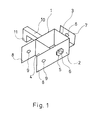
- FIG. 1 shows a holding frame according to the invention, which has a threaded hole (6) in the form of a nut (5) on the right side (2).
- a screw (13) can then be turned against the pile (12), so that the holding frame according to the invention is locked on the pile (12).
- the angle (7) is arranged on the front (3) of the holding frame.
- Lr can be slightly beveled upwards and outwards, as shown in this FIG. 1. It can also have a threaded hole (6) through which a screw (13) can be rotated, with the aid of which the shield (15) is clamped.
- FIG. 1 Also shown in FIG. 1 is the possibility of arranging retaining plates (8) projecting to the rear on the right side (2) and the left side (1). Bores (9) are made in these holding plates (8).
- a wind strut (14) can thus be hooked in here with a split pin which is inserted through the bores (9).
- FIG. 1 Also shown in FIG. 1 is the possibility of arranging an arm (10) on one side, here on the left side (1), which projects from the holding frame according to the invention.
- a square (11) is arranged at right angles to it.
- This square (11) ver preferably runs parallel to the left side (1) and the rear side (4); ie the square (11) preferably runs parallel to the post (12) of the sign stand.
- a lamp can be used to illuminate the sign, which has a suitable mounting option.
- a lamp is known for example from DE-GH 77 14 569.
- FIG. 2 shows the side view of a sign stand which is equipped with the holding frame according to the invention.
- the pile (12) is placed on a foot (16).
- a holding frame according to the invention is arranged on the lower edge of the shield (15) and has an angle (7) that is slightly beveled upwards.
- the sign (15) jams itself at this angle due to its own weight.
- the holding frames are locked against the post (12) by screws; the Sohrauben themselves cannot be seen in this figure (2).
- the nuts (5) are shown on the sides of the holding frame.
- the holding plates (8), in which bores (9) are arranged, can be clearly seen from the holding frame according to the invention.
- a wind strut (14) is arranged on the holding plates (8) of the upper holding frame.
- the wind strut (14) is suspended in a split pin, which is not shown here, which is inserted through the bores (9).
- the other end of the wind strut (14) is attached to the foot (16).
- the upper holding frame here in FIG. 2 has a screw (13) in the angle (7), with the aid of which the shield (15) is clamped in. You cannot see a nut that provides the thread for the screw (13) in the angle (7) of the upper holding frame.
- the screws themselves are not shown in detail in FIG. 2; they are located in the threaded holes (6) of the nuts (5) on the sides of the holding frame according to the invention and that the nut (5) is on the right side in the holding frame according to the invention, which grasps the plate (15) from below.
- the screw (13) for locking the retaining tooth on the post (12) is on the left-hand side, if reference is made to FIG.
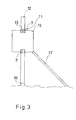
- FIG. 3 shows a front view of a sign stand according to the invention, which is equipped with the holding frame according to the invention.
- a support (17) can be seen on the side here, which protects the shield against tipping over to the side.
- On this support (17) can optionally in the holding sheets (8) with the holes (9) of a holding frame according to the invention.
- a square (11) protruding from the shield (15) can be seen.
- a lamp for illuminating the sign can be used in this square (11).
- a sign stand can also have more than two posts (12).
- Sign stands are preferred which have two posts (12) placed side by side; the shield (15) on these two piles (12) is held or clamped in each case from below and above by the holding frame according to the invention.
- Two piles (12) placed next to one another in this way can be braced in a known manner in order to give the sign stand the necessary rigidity.
- the holding frame according to the invention ensures a particularly strong non-positive connection of the shield (15) to the pile (12), such a bracing of several piles (12) can be omitted when using the holding frame according to the invention.
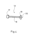
- FIG. 4 shows a preferred screw (13) for locking the holding frame on the post (12).
- This screw (13) has a pressure plate (19) on its front side; A spike (20) projecting outward beyond the pressure plate. This spike can dig into a wooden pile (12), so that slipping of the holding frame according to the invention on the pile (12) is completely prevented.
- the reference number (18 ') denotes the thread of the screw (13).
- the screw has a head (17) on the back; it is designed as an octagonal head in the illustration. Other head shapes, such as an Allen key can also be used.
- a screw with an Allen head does not have to be formed by forging with the head (17) or the pressure plate (19) after it has been screwed into the threaded hole (6) with the thread (18).
Landscapes
- Engineering & Computer Science (AREA)
- Physics & Mathematics (AREA)
- General Physics & Mathematics (AREA)
- Theoretical Computer Science (AREA)
- Architecture (AREA)
- Civil Engineering (AREA)
- Structural Engineering (AREA)
- Road Signs Or Road Markings (AREA)
Priority Applications (1)
| Application Number | Priority Date | Filing Date | Title |
|---|---|---|---|
| AT79104785T ATE10237T1 (de) | 1979-10-26 | 1979-11-30 | Schilderstaender mit ueberwurf-halterahmen. |
Applications Claiming Priority (2)
| Application Number | Priority Date | Filing Date | Title |
|---|---|---|---|
| DE7930368 | 1979-10-26 | ||
| DE7930368U | 1979-10-26 |
Publications (3)
| Publication Number | Publication Date |
|---|---|
| EP0028662A2 true EP0028662A2 (fr) | 1981-05-20 |
| EP0028662A3 EP0028662A3 (en) | 1981-09-02 |
| EP0028662B1 EP0028662B1 (fr) | 1984-11-07 |
Family
ID=6708576
Family Applications (1)
| Application Number | Title | Priority Date | Filing Date |
|---|---|---|---|
| EP79104785A Expired EP0028662B1 (fr) | 1979-10-26 | 1979-11-30 | Support pour signaux à manchons de maintien d'un panneau |
Country Status (4)
| Country | Link |
|---|---|
| US (1) | US4412396A (fr) |
| EP (1) | EP0028662B1 (fr) |
| AT (1) | ATE10237T1 (fr) |
| DE (1) | DE2967292D1 (fr) |
Cited By (5)
| Publication number | Priority date | Publication date | Assignee | Title |
|---|---|---|---|---|
| US4793083A (en) * | 1986-10-27 | 1988-12-27 | Mcdonald Angus E | Sign holder |
| EP0556415A1 (fr) * | 1992-02-12 | 1993-08-25 | Müller & Baum GmbH & Co. KG | Socle pour éléments de treillis d'une clôture mobile |
| GB2272096A (en) * | 1992-10-28 | 1994-05-04 | Edo Smitshuijzen | Improvements in and relating to clamps |
| AU725156B2 (en) * | 1997-02-06 | 2000-10-05 | Roadside Products Pty Ltd | Guide post |
| CN107170395A (zh) * | 2017-07-17 | 2017-09-15 | 合肥师范学院 | 一种具有防风功能的广告展示牌 |
Families Citing this family (12)
| Publication number | Priority date | Publication date | Assignee | Title |
|---|---|---|---|---|
| US4641448A (en) * | 1985-01-18 | 1987-02-10 | Apco Graphics, Inc. | Post cap apparatus |
| USD453535S1 (en) | 2000-10-13 | 2002-02-12 | Signex As | Information carrier |
| US6719249B2 (en) * | 2002-05-02 | 2004-04-13 | Macintyre S. Scott | Target support |
| US7726657B2 (en) * | 2007-09-20 | 2010-06-01 | Matt Shalosky | Target stand system |
| US8720844B2 (en) | 2010-04-28 | 2014-05-13 | Anthony J. Westimayer | Structure for coupling items such as signs and cameras to a fixed support structure |
| CN103276676B (zh) * | 2013-05-22 | 2015-08-12 | 北京市市政专业设计院股份公司 | 交通诱导显示屏架 |
| US9631770B2 (en) * | 2015-04-06 | 2017-04-25 | Edward James Holestine | Bracket for fixing a panel to a t-post |
| CN104989164A (zh) * | 2015-07-08 | 2015-10-21 | 国网山东烟台市牟平区供电公司 | 一种戗杆固定强化装置 |
| WO2018237142A1 (fr) * | 2017-06-22 | 2018-12-27 | Westfahl Erick | Système de clôture portative |
| CA3079185A1 (fr) * | 2019-04-24 | 2020-10-24 | Cbm Non-Conductive Solutions Llc | Ensembles barrieres modulaires non conductrices et procedes connexes |
| US11473720B2 (en) * | 2019-12-02 | 2022-10-18 | Ex Nihilo, LLC | Hanger attachment for posts |
| US20210233437A1 (en) * | 2020-01-24 | 2021-07-29 | William Brian Vincil | Sign assembly |
Family Cites Families (15)
| Publication number | Priority date | Publication date | Assignee | Title |
|---|---|---|---|---|
| US1529752A (en) * | 1922-11-10 | 1925-03-17 | Municipal Street Sign Co Inc | Sign frame and upright |
| US1874884A (en) * | 1931-06-18 | 1932-08-30 | S G Adams Company | Traffic sign or signal |
| US2025004A (en) * | 1934-11-08 | 1935-12-17 | American Steel & Wire Co | Support |
| US2372111A (en) * | 1942-04-30 | 1945-03-20 | Norberg Clarance | Folding target holder |
| US2552745A (en) * | 1947-08-29 | 1951-05-15 | Sr Nobe D Stanley | Adjustable sign stake |
| US2559302A (en) * | 1949-03-28 | 1951-07-03 | Louft Nathan | Sign post |
| US2819548A (en) * | 1955-09-14 | 1958-01-14 | Talmage D Campbell | Sign structure |
| US2848117A (en) * | 1956-05-11 | 1958-08-19 | Miller Allan | Street decoration support bracket |
| US3058246A (en) * | 1958-10-20 | 1962-10-16 | William A Schoeffier | Sign holder |
| FR1529767A (fr) * | 1967-04-27 | 1968-06-21 | Mode de classement de correspondance et appareillage pour sa mise en oeuvre | |
| NL159154B (nl) * | 1968-11-08 | 1979-01-15 | Bastiaan Frans Dorsman | Bevestiging voor een verkeers- of ander aanwijs- of dergelijk bord aan een paal. |
| FR2053636A5 (fr) * | 1969-07-11 | 1971-04-16 | Matson C G | |
| US3620496A (en) * | 1969-10-15 | 1971-11-16 | Bonel Co | Support structures for signs and the like |
| FR2131140A5 (fr) * | 1971-03-31 | 1972-11-10 | Vallette Et Pavon Ets | |
| DE2800420C2 (de) * | 1978-01-05 | 1980-01-24 | Hermann 6800 Mannheim Silbernagel | Schilderhalter |
-
1979
- 1979-11-30 AT AT79104785T patent/ATE10237T1/de not_active IP Right Cessation
- 1979-11-30 EP EP79104785A patent/EP0028662B1/fr not_active Expired
- 1979-11-30 DE DE7979104785T patent/DE2967292D1/de not_active Expired
-
1980
- 1980-01-17 US US06/113,110 patent/US4412396A/en not_active Expired - Lifetime
Cited By (6)
| Publication number | Priority date | Publication date | Assignee | Title |
|---|---|---|---|---|
| US4793083A (en) * | 1986-10-27 | 1988-12-27 | Mcdonald Angus E | Sign holder |
| EP0556415A1 (fr) * | 1992-02-12 | 1993-08-25 | Müller & Baum GmbH & Co. KG | Socle pour éléments de treillis d'une clôture mobile |
| GB2272096A (en) * | 1992-10-28 | 1994-05-04 | Edo Smitshuijzen | Improvements in and relating to clamps |
| AU725156B2 (en) * | 1997-02-06 | 2000-10-05 | Roadside Products Pty Ltd | Guide post |
| CN107170395A (zh) * | 2017-07-17 | 2017-09-15 | 合肥师范学院 | 一种具有防风功能的广告展示牌 |
| CN107170395B (zh) * | 2017-07-17 | 2022-12-09 | 合肥师范学院 | 一种具有防风功能的广告展示牌 |
Also Published As
| Publication number | Publication date |
|---|---|
| EP0028662A3 (en) | 1981-09-02 |
| US4412396A (en) | 1983-11-01 |
| EP0028662B1 (fr) | 1984-11-07 |
| ATE10237T1 (de) | 1984-11-15 |
| DE2967292D1 (en) | 1984-12-13 |
Similar Documents
| Publication | Publication Date | Title |
|---|---|---|
| DE2725057C2 (fr) | ||
| EP0028662B1 (fr) | Support pour signaux à manchons de maintien d'un panneau | |
| DE4115597A1 (de) | Vorrichtung zum halten von schalungselementen | |
| DE202024100688U1 (de) | Vorrichtung zur Anbringung von Absturzsicherungen an Baugerüsten | |
| DE9004887U1 (de) | Vorrichtung zum Befestigen von Bekleidungsplatten, insbesondere Wandbekleidungsplatten | |
| DE19511906A1 (de) | Sichtschutzzaun | |
| DE1684308A1 (de) | Haltevorrichtung fuer vertikal einzumauernde Pfosten | |
| DE1804002A1 (de) | Schalung fuer aus Beton zu giessende Deckentraeger | |
| DE60037063T2 (de) | Geländer aus mehreren miteinander verbindbaren Einzelelementen, insbesondere für Balkone und Treppen | |
| DE7930368U1 (de) | Schilderständer mit Überwurf -Halterahmen | |
| DE202005005831U1 (de) | Neigungseinstellbare Aufstiegshilfe | |
| DE7008866U (de) | Verankerung zur freihaengenden befestigung vorgefertigter wand- oder fassadenplatten. | |
| EP0593017B1 (fr) | Pièce de raccordement | |
| DE2321925A1 (de) | Schalungstraeger | |
| DE4426257C2 (de) | Einrichtung zur Aufnahme und zum Transport von Schalungszubehör | |
| DE3503186C2 (fr) | ||
| DE4005096C1 (en) | Sports stadium barrier fence - comprises screw-on frames and releasable planks bearing against ground anchor posts | |
| CH675143A5 (en) | Support for shuttering panels for concrete floors - comprises bar and slotted metal plate to enable shuttering to be adjusted horizontally and vertically | |
| DE102016108940B3 (de) | Vorrichtung zur Lagerung eines Hochsitzes auf dem Untergrund | |
| DE202023100314U1 (de) | Baugerüst | |
| DE202024001500U1 (de) | Vorrichtung zur Anbringung von Absturzsicherungen an Baugerüsten | |
| DE3824938A1 (de) | Podium | |
| EP1079042B1 (fr) | Support de coffrage de bordure de dalle | |
| DE9212556U1 (de) | Spielgerät | |
| DE202021102122U1 (de) | Spielgerät |
Legal Events
| Date | Code | Title | Description |
|---|---|---|---|
| PUAI | Public reference made under article 153(3) epc to a published international application that has entered the european phase |
Free format text: ORIGINAL CODE: 0009012 |
|
| AK | Designated contracting states |
Designated state(s): AT BE CH DE FR GB IT LU NL SE |
|
| PUAL | Search report despatched |
Free format text: ORIGINAL CODE: 0009013 |
|
| AK | Designated contracting states |
Designated state(s): AT BE CH DE FR GB IT LU NL SE |
|
| 17P | Request for examination filed |
Effective date: 19810626 |
|
| ITF | It: translation for a ep patent filed | ||
| GRAA | (expected) grant |
Free format text: ORIGINAL CODE: 0009210 |
|
| AK | Designated contracting states |
Designated state(s): AT BE CH DE FR GB IT LU NL SE |
|
| REF | Corresponds to: |
Ref document number: 10237 Country of ref document: AT Date of ref document: 19841115 Kind code of ref document: T |
|
| PGFP | Annual fee paid to national office [announced via postgrant information from national office to epo] |
Ref country code: DE Payment date: 19841120 Year of fee payment: 6 |
|
| PG25 | Lapsed in a contracting state [announced via postgrant information from national office to epo] |
Ref country code: LU Free format text: LAPSE BECAUSE OF NON-PAYMENT OF DUE FEES Effective date: 19841130 |
|
| PGFP | Annual fee paid to national office [announced via postgrant information from national office to epo] |
Ref country code: CH Payment date: 19841203 Year of fee payment: 6 |
|
| REF | Corresponds to: |
Ref document number: 2967292 Country of ref document: DE Date of ref document: 19841213 |
|
| ET | Fr: translation filed | ||
| PGFP | Annual fee paid to national office [announced via postgrant information from national office to epo] |
Ref country code: FR Payment date: 19841226 Year of fee payment: 6 |
|
| PGFP | Annual fee paid to national office [announced via postgrant information from national office to epo] |
Ref country code: SE Payment date: 19841231 Year of fee payment: 6 |
|
| PLBE | No opposition filed within time limit |
Free format text: ORIGINAL CODE: 0009261 |
|
| STAA | Information on the status of an ep patent application or granted ep patent |
Free format text: STATUS: NO OPPOSITION FILED WITHIN TIME LIMIT |
|
| PGFP | Annual fee paid to national office [announced via postgrant information from national office to epo] |
Ref country code: AT Payment date: 19851118 Year of fee payment: 7 |
|
| 26N | No opposition filed | ||
| PGFP | Annual fee paid to national office [announced via postgrant information from national office to epo] |
Ref country code: NL Payment date: 19851130 Year of fee payment: 7 |
|
| PG25 | Lapsed in a contracting state [announced via postgrant information from national office to epo] |
Ref country code: CH Effective date: 19861130 Ref country code: BE Effective date: 19861130 Ref country code: AT Effective date: 19861130 |
|
| PG25 | Lapsed in a contracting state [announced via postgrant information from national office to epo] |
Ref country code: SE Effective date: 19861201 |
|
| BERE | Be: lapsed |
Owner name: SILBERNAGEL HERMANN Effective date: 19861130 |
|
| PG25 | Lapsed in a contracting state [announced via postgrant information from national office to epo] |
Ref country code: NL Effective date: 19870601 |
|
| NLV4 | Nl: lapsed or anulled due to non-payment of the annual fee | ||
| GBPC | Gb: european patent ceased through non-payment of renewal fee | ||
| PG25 | Lapsed in a contracting state [announced via postgrant information from national office to epo] |
Ref country code: FR Free format text: LAPSE BECAUSE OF NON-PAYMENT OF DUE FEES Effective date: 19870731 |
|
| REG | Reference to a national code |
Ref country code: CH Ref legal event code: PL |
|
| REG | Reference to a national code |
Ref country code: FR Ref legal event code: ST |
|
| PG25 | Lapsed in a contracting state [announced via postgrant information from national office to epo] |
Ref country code: DE Effective date: 19880802 |
|
| PG25 | Lapsed in a contracting state [announced via postgrant information from national office to epo] |
Ref country code: GB Effective date: 19881118 |
|
| EUG | Se: european patent has lapsed |
Ref document number: 79104785.5 Effective date: 19870902 |