EP0029230A2 - Dispositif de volet coupe-feu - Google Patents
Dispositif de volet coupe-feu Download PDFInfo
- Publication number
- EP0029230A2 EP0029230A2 EP80107039A EP80107039A EP0029230A2 EP 0029230 A2 EP0029230 A2 EP 0029230A2 EP 80107039 A EP80107039 A EP 80107039A EP 80107039 A EP80107039 A EP 80107039A EP 0029230 A2 EP0029230 A2 EP 0029230A2
- Authority
- EP
- European Patent Office
- Prior art keywords
- slide
- frame
- wall
- passage opening
- rail
- Prior art date
- Legal status (The legal status is an assumption and is not a legal conclusion. Google has not performed a legal analysis and makes no representation as to the accuracy of the status listed.)
- Withdrawn
Links
Images
Classifications
-
- A—HUMAN NECESSITIES
- A62—LIFE-SAVING; FIRE-FIGHTING
- A62C—FIRE-FIGHTING
- A62C2/00—Fire prevention or containment
- A62C2/06—Physical fire-barriers
- A62C2/22—Fire-dampers with provision for the removal of an obstacle, e.g. rails, conveyors, before closing the opening
Definitions
- the invention relates to a fire protection device on a wall or ceiling passage opening, with a frame attached to the wall or ceiling and a slide inside the frame guided by rollers in rails and movable into a closed position in front of the passage opening.
- the invention has for its object to design a fire protection device of the type mentioned so that the closing movement of the slide runs harmoniously and gently without expensive aids.
- the inclination can be optimally selected and adjusted.
- the entire construction and in particular sealing elements are protected.
- the device can be manufactured and assembled inexpensively because of its relatively simple construction.
- the inclination of the running rails will preferably be of the order of magnitude between 2 ° and 4 °.
- the fire protection device according to the invention is Particularly suitable for those applications in which the slide normally always assumes its closed position and is only opened by a drive when, for example, a carriage of a conveyor system passes the wall passage opening.
- the frame is equally suitable for installation on walls or ceilings. Depending on the type of installation, only the running rails need to be inclined accordingly in order to generate the required closing torque for the slide.
- a geared motor can be used as the motor drive, which is normally connected to the slide by a coupling device and is automatically disconnected in the event of a fire.
- the driving force can be transmitted, for example, via a pinion to a rack on the slide.
- the gear motor pinion can be engaged with the rack by a holding magnet. If the holding magnet is de-energized in the event of a fire, an elastic element, for example in the form of a weight or a spring, separates the pinion from the rack.
- the slide can have lateral sealing joints, which are placed so that they exist in the closed position Can seal joints. These sealing joints can be filled with a film material that swells when exposed to heat, such as vermiculite or the like.
- one or more layers of asbestos foam may be present inside the frame and / or between the frame and the wall or ceiling.
- the seal between the frame and slide can be labyrinthine.
- a fire protection closure device is operated in connection with a conveyor system or the like passing through the passage opening, then it can be advantageous according to the invention to mount a movable rail piece passing through the displacement range of the slide in its normal conveying position and to pivot it kinematically with the slide or its To couple the drive. In this way it is ensured that the closing movement of the slide is not hindered on the one hand and that the rail connection is automatically restored when the slide is opened.
- the coupling between the swiveling rail section and Slide can be done with a cable or a pull rod with a spring stop. Furthermore, a compensating device can be provided in order to achieve a desired leading or trailing of the rail piece with respect to the slide.
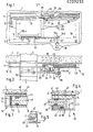
- the fire protection device shown in the drawing consists essentially of a fire protection frame 10 made of fire retardant or non-combustible material and a movably protected therein Slider 17.
- the fire protection frame 10 is fastened to a wall 1 in the area of a passage opening 2 for rails 4 of a conveyor system.
- the fire protection device can also be used for openings in ceilings.
- the fire protection frame 10 is of multi-shell construction, a rear cover plate 14 facing the wall 1 is separated from a front cover plate 13 by a horizontally or perpendicularly extending outer frame 11 and an inclined inner frame 12. Parallel to the approximately 2 0 to 4 ° relative to the horizontal plane inclination of the inner frame 12 10 rails 15 are laid within the frame, in which the slide 17 composed of two layers is guided on smooth-running rollers 18. Due to the inclination of the running rails 15, a force component derived from gravity and directed to the left in FIG. 1 is generated on the slide 17, which moves the slide 17 into its closed position in front of the passage opening two as soon as it is triggered by a trigger device (not shown) (for example one Holding magnets) is released.
- a trigger device not shown
- a trigger device for example one Holding magnets
- the slide 17 normally assumes its closed position indicated in FIGS. 3 and 4 and only if one is not shown vehicle wants to pass through the opening 4 through the rails 4, is prematurely opened by a motor drive.
- This motor drive consists of a geared motor 22 with a drive pinion 21 which normally engages in a rack 20 fastened to the slide 17.
- the geared motor 22 is rotatably supported by a motor mount 24 on a bearing block 23 which is fastened to the frame 10 and is held in the drive position by a holding magnet 25 as long as current flows through this holding magnet.
- a compression spring 26 pushes the motor mount 24 off and the drive pinion 21 is separated from the rack 20. Now, after triggering the slide 17 can automatically assume its closed position.
- a pivotable rail bridge 30 which is kinematically coupled to the sequence of movements of the slide.
- the rail bridge 30 is connected to a shaft 32 rotatably mounted in bearing blocks 33 with respect to the frame 10, at the end of which two rope pulleys 34a and 34b are fastened.
- a balance weight 38 acts on the rope pulley 34a via a rope 37 in order to keep the opening torque for the rail bridge 30 as small as possible.
- the second rope pulley 34b is connected to the slide 17 via a rope 35 with a deflection roller 36. In this way, the movement of the slide is automatically coupled with the pivoting movement of the rail bridge 30.
- the rail bridge can alternatively be coupled to the slider 17 via a drawbar, not shown, with a spring stop. 0 Appropriate dimensioning means that a lead or lag of the rail bridge can be set relative to the slide.
- lateral sealing joints 40 are incorporated into the slide 17 and filled with a filling material 41 which swells when exposed to heat and reliably seals existing joints in the event of a fire.
- This filling material can be composed of ten parts of vermiculite (unexpanded) and one part of an adhesive Miracol or the like.
- the frame 10 is deposited opposite the wall 1 with an asbestos foam layer 43, and in the closed position the front end edge of the slider 17 also bears against the inner frame 12 via an asbestos foam layer 43.
- sealing strip 45 On the side next to the rear edge of the slide 17 with a sealing joint 40 filled with filler material 41.
- This sealing strip 45 forms opposite cover strips 46 with which the inner surface of the front cover plate 13 of the frame 10 is occupied, a labyrinthine sealing joint.
- Fig. 5 shows a modified edge of the slide 17.
- the slide is provided with an iron 49 to which an angle iron 47 is welded.
- This angle iron engages under a counter iron 48 attached over the cover strip 46 in a hook-like manner. In this way, opening by possible sagging is avoided by the hooks 47, 48 engaging behind one another like hooks.
Landscapes
- Health & Medical Sciences (AREA)
- Public Health (AREA)
- Business, Economics & Management (AREA)
- Emergency Management (AREA)
- Special Wing (AREA)
- Building Environments (AREA)
Applications Claiming Priority (2)
| Application Number | Priority Date | Filing Date | Title |
|---|---|---|---|
| DE19792946058 DE2946058A1 (de) | 1979-11-15 | 1979-11-15 | Feuerschutzabschlussvorrichtung |
| DE2946058 | 1979-11-15 |
Publications (2)
| Publication Number | Publication Date |
|---|---|
| EP0029230A2 true EP0029230A2 (fr) | 1981-05-27 |
| EP0029230A3 EP0029230A3 (fr) | 1982-01-27 |
Family
ID=6086010
Family Applications (1)
| Application Number | Title | Priority Date | Filing Date |
|---|---|---|---|
| EP80107039A Withdrawn EP0029230A3 (fr) | 1979-11-15 | 1980-11-14 | Dispositif de volet coupe-feu |
Country Status (2)
| Country | Link |
|---|---|
| EP (1) | EP0029230A3 (fr) |
| DE (1) | DE2946058A1 (fr) |
Cited By (1)
| Publication number | Priority date | Publication date | Assignee | Title |
|---|---|---|---|---|
| EP0051917B1 (fr) * | 1980-09-26 | 1986-02-19 | Beecham Group Plc | Dérivés de benzofuranne-éthanolamine, leurs procédés de préparation et leur usage en médicine |
Family Cites Families (5)
| Publication number | Priority date | Publication date | Assignee | Title |
|---|---|---|---|---|
| DE2348854A1 (de) * | 1973-09-28 | 1975-04-17 | Flamex Ltd | Feuerschutzabschluss insbesondere fuer durch transportanlagen verbundene raeume |
| DE2547818C2 (de) * | 1975-10-25 | 1984-12-20 | abs-Brandschutz GmbH, 6501 Nieder Olm | Feuerschutzabschluß für eine Öffnung in Wänden oder Decken, welche von einer Förderanlage durchquert wird |
| DE2734641C3 (de) * | 1977-08-01 | 1981-01-22 | Buero Patent Ag, Glarus (Schweiz) | Beweglicher Abschluß für einen Wanddurchlaß einer Förderanlage o.dgl |
| DE2900369A1 (de) * | 1979-01-05 | 1980-07-17 | Ipu Ltd | Feuerabschlussanordnung |
| DE2929671A1 (de) * | 1979-07-21 | 1981-02-12 | Ipu Ltd | Feuerabschlussvorrichtung |
-
1979
- 1979-11-15 DE DE19792946058 patent/DE2946058A1/de not_active Withdrawn
-
1980
- 1980-11-14 EP EP80107039A patent/EP0029230A3/fr not_active Withdrawn
Cited By (1)
| Publication number | Priority date | Publication date | Assignee | Title |
|---|---|---|---|---|
| EP0051917B1 (fr) * | 1980-09-26 | 1986-02-19 | Beecham Group Plc | Dérivés de benzofuranne-éthanolamine, leurs procédés de préparation et leur usage en médicine |
Also Published As
| Publication number | Publication date |
|---|---|
| DE2946058A1 (de) | 1981-05-21 |
| EP0029230A3 (fr) | 1982-01-27 |
Similar Documents
| Publication | Publication Date | Title |
|---|---|---|
| DE19651947C1 (de) | Brandschutztür | |
| DE2126201A1 (de) | Schließvorrichtung zum Schließen der Lücke zwischen Gangway und Flugzeugtüre | |
| DE1564805A1 (de) | Strahlenschutzvorrichtung | |
| DE102010005455B4 (de) | Brandschutzbehang, Brandschutzabschluss sowie Herstellverfahren hierfür | |
| DE3803317A1 (de) | Feuerschutz-fahrstuhltuer | |
| DE2547818A1 (de) | Vorrichtung zum abdichten und schliessen von feuerschutzabschluessen fuer oeffnungen in einer wand oder decke | |
| EP0029230A2 (fr) | Dispositif de volet coupe-feu | |
| DE19607967A1 (de) | Schiebetüranlage | |
| DE8313824U1 (de) | Feuerabschluss fuer einen deckendurchbruch einer paternosterfoerderanlage | |
| DE3417761A1 (de) | Feuerschutzabschluss zum verschliessen eines wand- oder deckendurchbruchs einer foerderanlage | |
| EP1801336A1 (fr) | Dispositif coordinateur de fermeture | |
| DE2758625C2 (de) | Verriegelungsvorrichtung zum Offenhalten eines Schiebetores | |
| DE2001349B2 (de) | Schwingfalttor | |
| DE942966C (de) | Nach oben schwingbarer Fluegel, insbesondere fuer Garagentore, mit am feststehenden Rahmen in mittlerer Hoehe angeordneten Lagerboecken | |
| EP0098839B1 (fr) | Dispositif de fermeture automatique pour la protection contre le feu par obturation des ouvertures | |
| DE2431800C2 (de) | Feuerbeständiges Tor, vorzugsweise Schiebetor | |
| DE2348854A1 (de) | Feuerschutzabschluss insbesondere fuer durch transportanlagen verbundene raeume | |
| DE19817440B4 (de) | Schiebetüranlage | |
| DE102011053989B4 (de) | Feuerschutzschiebetor | |
| DE2929671A1 (de) | Feuerabschlussvorrichtung | |
| DE2947582A1 (de) | Feuerabschlussvorrichtung | |
| DE2720684A1 (de) | Feuerschutzabschluss | |
| DE4131151C1 (en) | Fireproof cladding for wall through passage for leads - includes intumescent material expanding when heated to fill and close wall opening | |
| CH705747B1 (de) | Insektenschutzgitter für Wandöffnungen, insbesondere für Tür- oder Fernsteröffnungen. | |
| DE2900369A1 (de) | Feuerabschlussanordnung |
Legal Events
| Date | Code | Title | Description |
|---|---|---|---|
| PUAI | Public reference made under article 153(3) epc to a published international application that has entered the european phase |
Free format text: ORIGINAL CODE: 0009012 |
|
| AK | Designated contracting states |
Designated state(s): AT BE CH FR GB NL |
|
| PUAL | Search report despatched |
Free format text: ORIGINAL CODE: 0009013 |
|
| AK | Designated contracting states |
Designated state(s): AT BE CH FR GB NL |
|
| STAA | Information on the status of an ep patent application or granted ep patent |
Free format text: STATUS: THE APPLICATION IS DEEMED TO BE WITHDRAWN |
|
| 18D | Application deemed to be withdrawn |
Effective date: 19830102 |
|
| RIN1 | Information on inventor provided before grant (corrected) |
Inventor name: RITZ, OTTO, ING.GRAD. |