EP0029383A1 - Vorrichtung zum Zusammenfügen der Enden optischer Fasern - Google Patents
Vorrichtung zum Zusammenfügen der Enden optischer Fasern Download PDFInfo
- Publication number
- EP0029383A1 EP0029383A1 EP19800401575 EP80401575A EP0029383A1 EP 0029383 A1 EP0029383 A1 EP 0029383A1 EP 19800401575 EP19800401575 EP 19800401575 EP 80401575 A EP80401575 A EP 80401575A EP 0029383 A1 EP0029383 A1 EP 0029383A1
- Authority
- EP
- European Patent Office
- Prior art keywords
- rods
- fibers
- shoe
- optical fibers
- force
- Prior art date
- Legal status (The legal status is an assumption and is not a legal conclusion. Google has not performed a legal analysis and makes no representation as to the accuracy of the status listed.)
- Granted
Links
- 230000003287 optical effect Effects 0.000 title abstract description 9
- 239000000835 fiber Substances 0.000 claims abstract description 67
- 238000005452 bending Methods 0.000 claims abstract description 14
- 238000003825 pressing Methods 0.000 claims abstract description 11
- 239000013013 elastic material Substances 0.000 claims abstract description 5
- 239000013307 optical fiber Substances 0.000 claims description 20
- 230000000694 effects Effects 0.000 claims description 7
- 230000008878 coupling Effects 0.000 claims description 6
- 238000010168 coupling process Methods 0.000 claims description 6
- 238000005859 coupling reaction Methods 0.000 claims description 6
- 239000007788 liquid Substances 0.000 claims description 3
- 229910000760 Hardened steel Inorganic materials 0.000 claims description 2
- 239000011248 coating agent Substances 0.000 claims 1
- 238000000576 coating method Methods 0.000 claims 1
- 239000000463 material Substances 0.000 claims 1
- 238000000034 method Methods 0.000 description 9
- 230000007547 defect Effects 0.000 description 6
- 238000013459 approach Methods 0.000 description 4
- 238000005304 joining Methods 0.000 description 4
- 210000000056 organ Anatomy 0.000 description 3
- 230000005540 biological transmission Effects 0.000 description 2
- 230000006835 compression Effects 0.000 description 2
- 238000007906 compression Methods 0.000 description 2
- 230000006866 deterioration Effects 0.000 description 2
- 230000001627 detrimental effect Effects 0.000 description 2
- 239000012535 impurity Substances 0.000 description 2
- 238000003780 insertion Methods 0.000 description 2
- 230000037431 insertion Effects 0.000 description 2
- 238000004519 manufacturing process Methods 0.000 description 2
- 239000000853 adhesive Substances 0.000 description 1
- 238000004026 adhesive bonding Methods 0.000 description 1
- 230000001070 adhesive effect Effects 0.000 description 1
- 230000000903 blocking effect Effects 0.000 description 1
- 238000004140 cleaning Methods 0.000 description 1
- 230000002950 deficient Effects 0.000 description 1
- 229910003460 diamond Inorganic materials 0.000 description 1
- 239000010432 diamond Substances 0.000 description 1
- 230000008030 elimination Effects 0.000 description 1
- 238000003379 elimination reaction Methods 0.000 description 1
- 210000003811 finger Anatomy 0.000 description 1
- 238000005498 polishing Methods 0.000 description 1
- 238000013138 pruning Methods 0.000 description 1
- 230000001846 repelling effect Effects 0.000 description 1
- 239000011009 synthetic ruby Substances 0.000 description 1
- 210000003813 thumb Anatomy 0.000 description 1
- 239000012780 transparent material Substances 0.000 description 1
Images

Classifications
-
- G—PHYSICS
- G02—OPTICS
- G02B—OPTICAL ELEMENTS, SYSTEMS OR APPARATUS
- G02B6/00—Light guides; Structural details of arrangements comprising light guides and other optical elements, e.g. couplings
- G02B6/24—Coupling light guides
- G02B6/255—Splicing of light guides, e.g. by fusion or bonding
-
- G—PHYSICS
- G02—OPTICS
- G02B—OPTICAL ELEMENTS, SYSTEMS OR APPARATUS
- G02B6/00—Light guides; Structural details of arrangements comprising light guides and other optical elements, e.g. couplings
- G02B6/24—Coupling light guides
- G02B6/255—Splicing of light guides, e.g. by fusion or bonding
- G02B6/2555—Alignment or adjustment devices for aligning prior to splicing
- G02B6/2556—Alignment or adjustment devices for aligning prior to splicing including a fibre supporting member inclined to the bottom surface of the alignment means
-
- G—PHYSICS
- G02—OPTICS
- G02B—OPTICAL ELEMENTS, SYSTEMS OR APPARATUS
- G02B6/00—Light guides; Structural details of arrangements comprising light guides and other optical elements, e.g. couplings
- G02B6/24—Coupling light guides
- G02B6/36—Mechanical coupling means
- G02B6/38—Mechanical coupling means having fibre to fibre mating means
- G02B6/3801—Permanent connections, i.e. wherein fibres are kept aligned by mechanical means
- G02B6/3803—Adjustment or alignment devices for alignment prior to splicing
- G02B6/3805—Adjustment or alignment devices for alignment prior to splicing with a fibre-supporting member inclined to the bottom surface of the alignment means
-
- G—PHYSICS
- G02—OPTICS
- G02B—OPTICAL ELEMENTS, SYSTEMS OR APPARATUS
- G02B6/00—Light guides; Structural details of arrangements comprising light guides and other optical elements, e.g. couplings
- G02B6/24—Coupling light guides
- G02B6/36—Mechanical coupling means
- G02B6/38—Mechanical coupling means having fibre to fibre mating means
- G02B6/3807—Dismountable connectors, i.e. comprising plugs
- G02B6/3833—Details of mounting fibres in ferrules; Assembly methods; Manufacture
- G02B6/3834—Means for centering or aligning the light guide within the ferrule
- G02B6/3841—Means for centering or aligning the light guide within the ferrule using rods, balls for light guides
-
- G—PHYSICS
- G02—OPTICS
- G02B—OPTICAL ELEMENTS, SYSTEMS OR APPARATUS
- G02B6/00—Light guides; Structural details of arrangements comprising light guides and other optical elements, e.g. couplings
- G02B6/24—Coupling light guides
- G02B6/36—Mechanical coupling means
- G02B6/38—Mechanical coupling means having fibre to fibre mating means
- G02B6/3807—Dismountable connectors, i.e. comprising plugs
- G02B6/381—Dismountable connectors, i.e. comprising plugs of the ferrule type, e.g. fibre ends embedded in ferrules, connecting a pair of fibres
- G02B6/3818—Dismountable connectors, i.e. comprising plugs of the ferrule type, e.g. fibre ends embedded in ferrules, connecting a pair of fibres of a low-reflection-loss type
- G02B6/382—Dismountable connectors, i.e. comprising plugs of the ferrule type, e.g. fibre ends embedded in ferrules, connecting a pair of fibres of a low-reflection-loss type with index-matching medium between light guides
Definitions
- the present invention relates to a device for joining two optical fibers.
- optical fibers constitute the connecting channel between transmitting or source organs, and receiving organs. In most cases, it is difficult or even impossible to use fibers made in one piece. Fiber to fiber connections must therefore be made either permanent or removable. These connections will be called in the following abutment.
- the fibers can then have cuts sometimes skewed by several degrees, however allowing their use.
- an exaggerated pressure force, exerted by the aforementioned organ, and acting perpendicular to the fiber can be a cause of rupture due to a guide profile having defects or, more often, deformations making this guidance uncertain.
- the devices of the prior art do not generally allow sufficient reproducibility, which constitutes a major drawback, the optical connection cables generally comprising numerous pairs of fibers having to be butted.
- the invention proposes a device which, while overcoming the drawbacks which have just been mentioned, only uses simple and inexpensive components.
- the subject of the invention is therefore a abutment device mainly characterized in that it comprises means for guiding the optical fibers to be butted comprising a contiguous pair of straight rods, flexible and of cylindrical section forming a guide cradle in which slide optical fibers, and pressing means acting on at least one pad of elastic material; the shoe simultaneously exerting a driving force on one of the two fibers, sliding it in the guide cradle towards the other fiber to be butted, and a bending force on each of the rods, bending the pair of rods.
- FIG. 1 shows schematically in an amplified manner the defect that may appear when using such a joining method.
- Another defect that may arise during abutment is as follows: even if the two fibers remain parallel to the support plane, because their ends may have a slight bevel due to the pruning process as was previously recalled , during the junction, these two fibers may tend to overlap, leading to the same defective result as that of FIG. 1.
- FIG. 2 illustrates one of the most important arrangements of the invention, remedying this defect.
- the means for guiding the two optical fibers allowing their bringing together are constituted by a contiguous pair of flexible rectilinear rods and cylindrical sections forming guide cradle. These rods are held at their only ends and left free in their central part.
- a sliding force is exerted simultaneously on at least one of the fibers to achieve the abutment, this ehtraine a bending force on the rods so that they bend slightly. Due to this curvature, the optical fibers can no longer exhibit the defect of FIG.
- the sliding and bending forces are exerted using pads of elastic material, that is to say deformable.
- This shoe partially covers, as illustrated in FIG. 3, the two rods 3 and 4 constituting the guide cradle.
- the shoe 5 exerts a bending force, symbolized by the arrow F 3 , on the assembly constituted by the guide rods 3 and 4 as well as the fiber 1, due to the deformation of the elastic material constituting the shoe, this force can be broken down into two forces F 301 and F 302 whose directions form an angle a between them.
- These two forces F3 01 and F 302 have the double effect, on the one hand, the rods 3 and 4 being held at their only end, to arch them and, on the other hand, to keep them contiguous.
- the abutment device for holding the two rods in place, comprises a receptacle consisting of a flat base surmounted by two side walls, in each of which a shaped groove has been formed of V intended to receive one of the ends of the guide rods.
- This arrangement illustrated in Figure 4 in which one of the side walls 7 is shown, offers the possibility of a slight tilting of the plane passing through the axes 0 1 0 2 of the fibers relative to the reference axis OX.
- This V-shaped groove arrangement 9 is self-centering and ensures the correct attitude of the guide cradle despite a slight misalignment of the bending force F3 exerted on the pressing shoe 5 relative to the axis OZ . The directions in which the forces are exerted therefore need not be determined with precision.
- the forces exerted on the guide and pressing pads are obtained using springs in the form of a hairpin secured to a movable frame.
- one end of the spring is fixed to the pressing and holding pad, the other end being positioned in a cell formed in the movable frame.
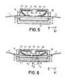
- FIG. 5 we find, in section, the receptacle comprising the base 11 and its side walls 7 and 8 in which the V-shaped grooves 9 and 10 have been made, intended to support at their ends the rods forming rails of guide 3 and 4.
- the pressing frame 14 is in the form of a cover which fits onto the receptacle comprising the base 11. In its upper part, cells 16 and 17 have been made to receive the pin springs at hair 12 and 13. At rest, the base and the pressing frame 14 are kept at a sufficient distance so that the springs 12 and 13 do not exert a bending force on the rods 3 and 4. We can then slide manually the optical fibers 1 and 2 between the guide rails formed by these rods.
- the two fibers When the pressure will increase, the two fibers will slide towards each other until blocking when the junction is made. Then the shoe will slide on the guide rods 3 and 4 and on the fiber associated with it without exerting stresses detrimental to this fiber.
- the joining of two fibers can therefore be carried out under the best conditions, in a reproducible manner, without risk of deterioration of the fibers to be butted together.
- the forces exerted by the pressing pads can be calibrated. This can be done very simply because the amplitude of these forces depends only on the difference between the base 11 and the frame 14 (and the elasticity coefficient of the springs, subject to an initial choice).
- the frame 14 can be provided in its center with a window 15.
- This window 15 can be used for several purposes: checking that no impurity has slipped between the contact faces of the fibers, following the movement of these fibers, injecting possibly an index liquid, or even a liquid adhesive allowing the final fixing of the two fibers.
- the frame as a whole can be made of a transparent material to better follow the movement of the fibers.
- the abutment device allows their elimination in a very simple manner. It suffices, the springs being in the position illustrated in FIG. 5, to push one of the fibers manually. The other fiber moves back and leaves the device thus making the ends of the two fibers accessible. It only remains to ensure the cleaning these ends and repelling the first fiber using the second, and recommencing the abutment operation after the insertion of these two fibers and junction in the central zone of the device.
- the coupling means of the frame 14 with the base 11 can be carried out very simply using a clamping screw system.
- One end of this clamping screw must be fixed, for example relative to the base 11, the thread of the screw driving the frame 14 and bringing these two mechanical parts together when the screw is rotated.
- the head of the screw can be provided with a drive wheel, or on the contrary be provided with a simple slot which can be driven by a screwdriver and is flush with the exterior surface of the frame 14.
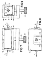
- FIGS. 7 to 9 showing the views in elevation, in plan and in profile of the abutment device of the invention.
- the frame forming the cover 14 is made integral with a support 18 provided with a clamping screw 21.
- a window 19 revealing the window 15 is also formed in the support 18.
- This clamping screw 21 drives a plate 20 on which is deposited the base 11.
- the screw 21 is provided with a drive wheel 22.
- the thumb wheel 12 can drive a graduated disc moving in front of an index finger and allowing a dosage of the amplitude of the force exerted by the springs, amplitude which depends only on the spacing of the frame 14 and the plate 20.
- the guide rods 3 and 4 are separate parts of the abutment device. Indeed these rods are removable and, this is an additional advantage of the invention, due to the V shape of the retaining groove, the diameter of these rods can be chosen according to the diameter of the fibers to be butted. It should also be noted that these rods are made integral with the fibers when the abutment is made by gluing to achieve fixed junctions. These guide rods can be made of polished hardened steel, to avoid any asperities detrimental to the sliding of the fibers, and by example be made up of rods known as rods.
- the invention therefore makes it possible, with a simple manipulation (turning a tightening screw), to carry out several operations simultaneously allowing the abutment of two optical fibers repeatedly, while offering maximum security as to the smooth running of the operation and without risk fiber deterioration.
- the initial manipulations for introducing the two fibers to abut into the device are reduced to their simplest expression, these two fibers not having to be positioned precisely, nor even to be brought into contact with one another. with the other at the start of the operation.
- none of the components necessary for the production of an abutment device according to the invention requires, for their manufacture, precision fitting techniques and therefore the device can be obtained in a simple and inexpensive.
- one of the two fibers can be made integral with the guide or in its extension, in this case a single spring is sufficient, on the one hand, to bring the mobile optical fiber closer to the fixed fiber, and, on the other hand, to ensure the bending of the guide rods.
- a cable comprising several fibers can be joined fiber by fiber to another cable using one or more abutment devices according to the invention.
- the clamping screw coupling system can also be replaced by a spring ensuring a calibrated pressure between the two moving parts or by a lever performing this function.
Landscapes
- Physics & Mathematics (AREA)
- General Physics & Mathematics (AREA)
- Optics & Photonics (AREA)
- Engineering & Computer Science (AREA)
- Plasma & Fusion (AREA)
- Mechanical Coupling Of Light Guides (AREA)
Applications Claiming Priority (2)
| Application Number | Priority Date | Filing Date | Title |
|---|---|---|---|
| FR7928040 | 1979-11-14 | ||
| FR7928040A FR2469726A1 (fr) | 1979-11-14 | 1979-11-14 | Dispositif d'aboutement de deux fibres optiques |
Publications (2)
| Publication Number | Publication Date |
|---|---|
| EP0029383A1 true EP0029383A1 (de) | 1981-05-27 |
| EP0029383B1 EP0029383B1 (de) | 1983-05-11 |
Family
ID=9231655
Family Applications (1)
| Application Number | Title | Priority Date | Filing Date |
|---|---|---|---|
| EP19800401575 Expired EP0029383B1 (de) | 1979-11-14 | 1980-11-04 | Vorrichtung zum Zusammenfügen der Enden optischer Fasern |
Country Status (3)
| Country | Link |
|---|---|
| EP (1) | EP0029383B1 (de) |
| DE (1) | DE3063176D1 (de) |
| FR (1) | FR2469726A1 (de) |
Cited By (13)
| Publication number | Priority date | Publication date | Assignee | Title |
|---|---|---|---|---|
| EP0136201A3 (en) * | 1983-08-08 | 1985-07-31 | Alliance Technique Industrielle | Process for joining optical fibres, and optical splice obtained |
| EP0072637A3 (de) * | 1981-08-18 | 1985-11-27 | LUCAS INDUSTRIES public limited company | Faseroptisches Verbindungsstück |
| US4556282A (en) * | 1982-09-17 | 1985-12-03 | Delebecque Robert P | Device for connecting optical fibers |
| FR2567656A1 (fr) * | 1984-07-16 | 1986-01-17 | Alliance Tech Ind | Procede de raccordement de fibres optiques par collage sur une piece de liaison, et epissure optique ainsi obtenue |
| EP0106134B1 (de) * | 1982-09-14 | 1987-08-12 | GTE Products Corporation | Gehäuse für eine fiberoptische Verbindung |
| EP0269409A3 (en) * | 1986-11-24 | 1988-09-07 | Siecor Corporation | Rematable optical splice utilizing rods |
| EP0851250A1 (de) * | 1996-12-30 | 1998-07-01 | Alcatel | Spleiss-Modul für optische Fasern |
| US5812718A (en) * | 1996-03-27 | 1998-09-22 | Minnesota Mining And Manufacturing Company | Method for connecting optical fibers and the interconnection |
| GB2339029A (en) * | 1998-06-29 | 2000-01-12 | Optical Services & Sales Ltd | Passive optical fibre aligner with alignment rods |
| GB2376307A (en) * | 2001-06-07 | 2002-12-11 | Melles Griot Ltd | Bending an optic fibre in a groove to allow holding and rotation |
| WO2011025779A1 (en) * | 2009-08-31 | 2011-03-03 | Corning Cable Systems Llc | Optical fiber termination holder and methods for using the same |
| US20220026638A1 (en) * | 2019-02-06 | 2022-01-27 | Sumitomo Electric Optifrontier Co., Ltd. | Optical fiber fusion splicing method and fusion splicing device |
| CN116165745A (zh) * | 2023-02-14 | 2023-05-26 | 浙江康阔光智能科技有限公司 | 侧向光纤注光器及其应用的光纤熔接工艺 |
Citations (3)
| Publication number | Priority date | Publication date | Assignee | Title |
|---|---|---|---|---|
| FR2282650A1 (fr) * | 1974-08-19 | 1976-03-19 | Corning Glass Works | Connecteur pour guides d'ondes optiques |
| FR2390746A1 (fr) * | 1977-05-10 | 1978-12-08 | Cselt Centro Studi Lab Telecom | Dispositif pour la jonction de fibres et cables optiques |
| FR2395518A1 (fr) * | 1977-06-22 | 1979-01-19 | Comp Generale Electricite | Connecteur pour fibre optique |
-
1979
- 1979-11-14 FR FR7928040A patent/FR2469726A1/fr active Granted
-
1980
- 1980-11-04 DE DE8080401575T patent/DE3063176D1/de not_active Expired
- 1980-11-04 EP EP19800401575 patent/EP0029383B1/de not_active Expired
Patent Citations (3)
| Publication number | Priority date | Publication date | Assignee | Title |
|---|---|---|---|---|
| FR2282650A1 (fr) * | 1974-08-19 | 1976-03-19 | Corning Glass Works | Connecteur pour guides d'ondes optiques |
| FR2390746A1 (fr) * | 1977-05-10 | 1978-12-08 | Cselt Centro Studi Lab Telecom | Dispositif pour la jonction de fibres et cables optiques |
| FR2395518A1 (fr) * | 1977-06-22 | 1979-01-19 | Comp Generale Electricite | Connecteur pour fibre optique |
Non-Patent Citations (1)
| Title |
|---|
| IBM TECHNICAL DISCLOSURE BULLETIN Vol. 21, No. 11, Avril 1979, New York US L.D. COMERFORD: "Four-Pin Optical Fiber Connector", pages 4688-4689 * En entier * * |
Cited By (23)
| Publication number | Priority date | Publication date | Assignee | Title |
|---|---|---|---|---|
| EP0072637A3 (de) * | 1981-08-18 | 1985-11-27 | LUCAS INDUSTRIES public limited company | Faseroptisches Verbindungsstück |
| EP0106134B1 (de) * | 1982-09-14 | 1987-08-12 | GTE Products Corporation | Gehäuse für eine fiberoptische Verbindung |
| US4556282A (en) * | 1982-09-17 | 1985-12-03 | Delebecque Robert P | Device for connecting optical fibers |
| EP0136201A3 (en) * | 1983-08-08 | 1985-07-31 | Alliance Technique Industrielle | Process for joining optical fibres, and optical splice obtained |
| FR2567656A1 (fr) * | 1984-07-16 | 1986-01-17 | Alliance Tech Ind | Procede de raccordement de fibres optiques par collage sur une piece de liaison, et epissure optique ainsi obtenue |
| EP0269409A3 (en) * | 1986-11-24 | 1988-09-07 | Siecor Corporation | Rematable optical splice utilizing rods |
| AU592240B2 (en) * | 1986-11-24 | 1990-01-04 | Siecor Corporation | Rematable optical splice utilizing rods |
| AU714620B2 (en) * | 1996-03-27 | 2000-01-06 | Minnesota Mining And Manufacturing Company | Method for connecting optical fibers and the interconnection |
| US5812718A (en) * | 1996-03-27 | 1998-09-22 | Minnesota Mining And Manufacturing Company | Method for connecting optical fibers and the interconnection |
| WO1997036200A3 (en) * | 1996-03-27 | 2000-02-17 | Minnesota Mining & Mfg | Method for connecting optical fibers and the interconnection |
| US6048108A (en) * | 1996-12-30 | 2000-04-11 | Alcatel | Optical fiber splicing module |
| EP0851250A1 (de) * | 1996-12-30 | 1998-07-01 | Alcatel | Spleiss-Modul für optische Fasern |
| FR2757959A1 (fr) * | 1996-12-30 | 1998-07-03 | Alsthom Cge Alcatel | Module d'epissure pour fibres optiques |
| GB2339029B (en) * | 1998-06-29 | 2002-11-13 | Optical Services & Sales Ltd | Passive optical fibre aligner with alignment rods |
| GB2339029A (en) * | 1998-06-29 | 2000-01-12 | Optical Services & Sales Ltd | Passive optical fibre aligner with alignment rods |
| GB2376307A (en) * | 2001-06-07 | 2002-12-11 | Melles Griot Ltd | Bending an optic fibre in a groove to allow holding and rotation |
| GB2376307B (en) * | 2001-06-07 | 2003-05-14 | Melles Griot Ltd | Fibre rotation devices and methods |
| WO2011025779A1 (en) * | 2009-08-31 | 2011-03-03 | Corning Cable Systems Llc | Optical fiber termination holder and methods for using the same |
| US8417085B2 (en) | 2009-08-31 | 2013-04-09 | Corning Cable Systems Llc | Optical fiber termination holder and methods for using the same |
| US20220026638A1 (en) * | 2019-02-06 | 2022-01-27 | Sumitomo Electric Optifrontier Co., Ltd. | Optical fiber fusion splicing method and fusion splicing device |
| US12276841B2 (en) * | 2019-02-06 | 2025-04-15 | Sumitomo Electric Optifrontier Co., Ltd. | Optical fiber fusion splicing method and fusion splicing device |
| CN116165745A (zh) * | 2023-02-14 | 2023-05-26 | 浙江康阔光智能科技有限公司 | 侧向光纤注光器及其应用的光纤熔接工艺 |
| CN116165745B (zh) * | 2023-02-14 | 2023-09-22 | 浙江康阔光智能科技有限公司 | 侧向光纤注光器及其应用的光纤熔接工艺 |
Also Published As
| Publication number | Publication date |
|---|---|
| EP0029383B1 (de) | 1983-05-11 |
| FR2469726A1 (fr) | 1981-05-22 |
| DE3063176D1 (en) | 1983-06-16 |
| FR2469726B1 (de) | 1983-02-04 |
Similar Documents
| Publication | Publication Date | Title |
|---|---|---|
| EP0029383B1 (de) | Vorrichtung zum Zusammenfügen der Enden optischer Fasern | |
| CA1097111A (fr) | Fiche de connecteur fibre a fibre pour cable optique multifibre | |
| CA1131952A (fr) | Connecteur pour liaison a fibre optique | |
| EP1621905B1 (de) | Faseroptischer Stecker | |
| EP0089348B1 (de) | Zentrierhülse für das verbinden von optischen fasern | |
| EP0455141B1 (de) | Vorrichtung zum Quertrennen von einer optischen Glasfaser | |
| EP0011011A1 (de) | Endhülle eines Verbindungsstücks für eine optische Einzelfaser und mit derartiger Endhülle versehenes Verbindungsstück | |
| CA1087007A (fr) | Connecteur pour liaison a fibre optique | |
| EP0058594B1 (de) | Gerät zum gleichzeitigen Einlegen von optischen Fasern in einen strukturierten zylindrischen Tragekörper und Kabelherstellungsvorrichtung mit einem derartigen Gerät | |
| EP0090724B1 (de) | Vorrichtung zum Verbinden von optischen Fasern und Verfahren zu deren Benutzung | |
| FR2710157A1 (fr) | Procédé et dispositif pour aligner automatiquement des fibres optiques. | |
| EP0121460A1 (de) | Aufnahmestück für optische Fasern für eine Kupplungsvorrichtung und Verfahren zur Herstellung einer solchen Vorrichtung | |
| EP0036369B1 (de) | Verfahren und Vorrichtung zum Verbinden faseroptischer Kabel auf dem Arbeitsplatz | |
| EP0147363A1 (de) | Verfahren und Vorrichtung zur Positionierung einer optischen Faser bezüglich eines anderen optischen Bestandteiles | |
| CH684217A5 (fr) | Procédé et dispositif pour aligner des fibres optiques. | |
| EP0579521A1 (de) | Verfahren und Vorrichtung zum Schneiden einer optischen Faser | |
| EP0444566B1 (de) | Schneidezange mit kleiner Sperre zum Schneiden von optischen Fasern | |
| EP0146471B1 (de) | Verfahren und Vorrichtung zur halbpermanenten Verbindung von optischen Fasern | |
| FR2548390A1 (fr) | Dispositif de deplacement fin de l'extremite d'une fibre optique suivant deux axes orthogonaux | |
| FR2535069A1 (fr) | Embout de connexion optique multi-fibres, connecteur utilisant un tel embout et appareil pour le montage de fibres dans ledit embout | |
| EP0096608B1 (de) | Faseroptischer Kollimator, Anwendung zur Realisierung optischer Schaltervorrichtungen | |
| FR2747800A1 (fr) | Eclateur pour fibre multicoeur | |
| FR2781061A1 (fr) | Connecteur optique a nettoyage aise | |
| EP0138674B1 (de) | Verfahren zur Herstellung eines optischen Fasersteckverbinders und Vorrichtung zur Ausführung dieses Verfahrens | |
| WO2025021626A1 (fr) | Ensemble modulaire pour la gestion de la torsion d'un ruban à fibres optiques |
Legal Events
| Date | Code | Title | Description |
|---|---|---|---|
| PUAI | Public reference made under article 153(3) epc to a published international application that has entered the european phase |
Free format text: ORIGINAL CODE: 0009012 |
|
| AK | Designated contracting states |
Designated state(s): DE GB IT |
|
| 17P | Request for examination filed |
Effective date: 19811022 |
|
| ITF | It: translation for a ep patent filed | ||
| GRAA | (expected) grant |
Free format text: ORIGINAL CODE: 0009210 |
|
| AK | Designated contracting states |
Designated state(s): DE GB IT |
|
| REF | Corresponds to: |
Ref document number: 3063176 Country of ref document: DE Date of ref document: 19830616 |
|
| PLBE | No opposition filed within time limit |
Free format text: ORIGINAL CODE: 0009261 |
|
| STAA | Information on the status of an ep patent application or granted ep patent |
Free format text: STATUS: NO OPPOSITION FILED WITHIN TIME LIMIT |
|
| 26N | No opposition filed | ||
| ITTA | It: last paid annual fee | ||
| PGFP | Annual fee paid to national office [announced via postgrant information from national office to epo] |
Ref country code: GB Payment date: 19971007 Year of fee payment: 18 |
|
| PGFP | Annual fee paid to national office [announced via postgrant information from national office to epo] |
Ref country code: DE Payment date: 19971127 Year of fee payment: 18 |
|
| PG25 | Lapsed in a contracting state [announced via postgrant information from national office to epo] |
Ref country code: GB Free format text: LAPSE BECAUSE OF NON-PAYMENT OF DUE FEES Effective date: 19981104 |
|
| GBPC | Gb: european patent ceased through non-payment of renewal fee |
Effective date: 19981104 |
|
| PG25 | Lapsed in a contracting state [announced via postgrant information from national office to epo] |
Ref country code: DE Free format text: LAPSE BECAUSE OF NON-PAYMENT OF DUE FEES Effective date: 19991001 |