EP0147363A1 - Verfahren und Vorrichtung zur Positionierung einer optischen Faser bezüglich eines anderen optischen Bestandteiles - Google Patents
Verfahren und Vorrichtung zur Positionierung einer optischen Faser bezüglich eines anderen optischen Bestandteiles Download PDFInfo
- Publication number
- EP0147363A1 EP0147363A1 EP84810467A EP84810467A EP0147363A1 EP 0147363 A1 EP0147363 A1 EP 0147363A1 EP 84810467 A EP84810467 A EP 84810467A EP 84810467 A EP84810467 A EP 84810467A EP 0147363 A1 EP0147363 A1 EP 0147363A1
- Authority
- EP
- European Patent Office
- Prior art keywords
- translation
- support
- blades
- elastic deformation
- parts
- Prior art date
- Legal status (The legal status is an assumption and is not a legal conclusion. Google has not performed a legal analysis and makes no representation as to the accuracy of the status listed.)
- Granted
Links
- 238000000034 method Methods 0.000 title claims abstract description 18
- 239000013307 optical fiber Substances 0.000 title claims abstract description 9
- 230000003287 optical effect Effects 0.000 title claims abstract description 7
- 238000013519 translation Methods 0.000 claims abstract description 57
- 238000006073 displacement reaction Methods 0.000 claims description 47
- 230000005489 elastic deformation Effects 0.000 claims description 14
- 230000004308 accommodation Effects 0.000 claims description 11
- 230000036461 convulsion Effects 0.000 claims description 9
- 239000012528 membrane Substances 0.000 claims description 9
- 210000000056 organ Anatomy 0.000 claims description 2
- 238000005452 bending Methods 0.000 abstract description 2
- 230000014616 translation Effects 0.000 description 46
- 239000000835 fiber Substances 0.000 description 6
- 241001080024 Telles Species 0.000 description 4
- 230000000712 assembly Effects 0.000 description 4
- 238000000429 assembly Methods 0.000 description 4
- 238000004026 adhesive bonding Methods 0.000 description 3
- 230000000694 effects Effects 0.000 description 3
- 230000014509 gene expression Effects 0.000 description 3
- 230000003068 static effect Effects 0.000 description 3
- 230000008878 coupling Effects 0.000 description 2
- 238000010168 coupling process Methods 0.000 description 2
- 238000005859 coupling reaction Methods 0.000 description 2
- 239000000872 buffer Substances 0.000 description 1
- 230000006835 compression Effects 0.000 description 1
- 238000007906 compression Methods 0.000 description 1
- 239000013013 elastic material Substances 0.000 description 1
- 239000013536 elastomeric material Substances 0.000 description 1
- 230000009191 jumping Effects 0.000 description 1
- 239000000463 material Substances 0.000 description 1
- 239000011347 resin Substances 0.000 description 1
- 229920005989 resin Polymers 0.000 description 1
- 230000004434 saccadic eye movement Effects 0.000 description 1
Images


Classifications
-
- G—PHYSICS
- G02—OPTICS
- G02B—OPTICAL ELEMENTS, SYSTEMS OR APPARATUS
- G02B6/00—Light guides; Structural details of arrangements comprising light guides and other optical elements, e.g. couplings
- G02B6/24—Coupling light guides
- G02B6/42—Coupling light guides with opto-electronic elements
- G02B6/4201—Packages, e.g. shape, construction, internal or external details
- G02B6/4219—Mechanical fixtures for holding or positioning the elements relative to each other in the couplings; Alignment methods for the elements, e.g. measuring or observing methods especially used therefor
- G02B6/422—Active alignment, i.e. moving the elements in response to the detected degree of coupling or position of the elements
- G02B6/4226—Positioning means for moving the elements into alignment, e.g. alignment screws, deformation of the mount
-
- G—PHYSICS
- G02—OPTICS
- G02B—OPTICAL ELEMENTS, SYSTEMS OR APPARATUS
- G02B6/00—Light guides; Structural details of arrangements comprising light guides and other optical elements, e.g. couplings
- G02B6/24—Coupling light guides
- G02B6/36—Mechanical coupling means
- G02B6/38—Mechanical coupling means having fibre to fibre mating means
- G02B6/3801—Permanent connections, i.e. wherein fibres are kept aligned by mechanical means
- G02B6/3803—Adjustment or alignment devices for alignment prior to splicing
-
- Y—GENERAL TAGGING OF NEW TECHNOLOGICAL DEVELOPMENTS; GENERAL TAGGING OF CROSS-SECTIONAL TECHNOLOGIES SPANNING OVER SEVERAL SECTIONS OF THE IPC; TECHNICAL SUBJECTS COVERED BY FORMER USPC CROSS-REFERENCE ART COLLECTIONS [XRACs] AND DIGESTS
- Y10—TECHNICAL SUBJECTS COVERED BY FORMER USPC
- Y10T—TECHNICAL SUBJECTS COVERED BY FORMER US CLASSIFICATION
- Y10T29/00—Metal working
- Y10T29/49—Method of mechanical manufacture
- Y10T29/49826—Assembling or joining
- Y10T29/49895—Associating parts by use of aligning means [e.g., use of a drift pin or a "fixture"]
- Y10T29/49899—Associating parts by use of aligning means [e.g., use of a drift pin or a "fixture"] by multiple cooperating aligning means
-
- Y—GENERAL TAGGING OF NEW TECHNOLOGICAL DEVELOPMENTS; GENERAL TAGGING OF CROSS-SECTIONAL TECHNOLOGIES SPANNING OVER SEVERAL SECTIONS OF THE IPC; TECHNICAL SUBJECTS COVERED BY FORMER USPC CROSS-REFERENCE ART COLLECTIONS [XRACs] AND DIGESTS
- Y10—TECHNICAL SUBJECTS COVERED BY FORMER USPC
- Y10T—TECHNICAL SUBJECTS COVERED BY FORMER US CLASSIFICATION
- Y10T29/00—Metal working
- Y10T29/49—Method of mechanical manufacture
- Y10T29/49826—Assembling or joining
- Y10T29/49895—Associating parts by use of aligning means [e.g., use of a drift pin or a "fixture"]
- Y10T29/49901—Sequentially associating parts on stationary aligning means
-
- Y—GENERAL TAGGING OF NEW TECHNOLOGICAL DEVELOPMENTS; GENERAL TAGGING OF CROSS-SECTIONAL TECHNOLOGIES SPANNING OVER SEVERAL SECTIONS OF THE IPC; TECHNICAL SUBJECTS COVERED BY FORMER USPC CROSS-REFERENCE ART COLLECTIONS [XRACs] AND DIGESTS
- Y10—TECHNICAL SUBJECTS COVERED BY FORMER USPC
- Y10T—TECHNICAL SUBJECTS COVERED BY FORMER US CLASSIFICATION
- Y10T29/00—Metal working
- Y10T29/49—Method of mechanical manufacture
- Y10T29/49826—Assembling or joining
- Y10T29/49895—Associating parts by use of aligning means [e.g., use of a drift pin or a "fixture"]
- Y10T29/49902—Associating parts by use of aligning means [e.g., use of a drift pin or a "fixture"] by manipulating aligning means
Definitions
- the present invention relates to a method for positioning a first part such as for example an optical fiber, with respect to a second part, such as for example another optical component, in which the first part is mounted on a first support and the second part on a second support, and in which one of the supports is moved relative to the other.
- micro-optical elements such as optical fiber couplers
- the assembly of micro-optical elements requires extremely precise positioning of the parts to be coupled.
- the required precision is of the order of a micron for multimode fibers and of the order of a tenth of a micron for single-mode fibers.
- it is essential to be able to have a machine capable of grasping the parts to be assembled and of moving them relative to one another while respecting these specifications.
- the parts of the optical couplers must usually be able to be fixed permanently in the position obtained after their mutual positioning, by means of gluing or a screw. wise.
- the parts to be coupled may have a flat face by which they are brought into contact.
- the position adjustment is obtained by relative sliding in the contact plane, either by translation along two perpendicular axes, or by rotation about an axis.
- An adjustable application force is exerted so as to press the parts against each other in intimate contact during all the positioning and fixing operations of the assembly, to avoid deformations resulting from the assembly due in particular to removal of the bonding joints when the parts are not in direct contact.
- the present invention proposes to overcome the drawbacks of known systems by providing a device well suited to micro-displacements, which moreover allows assembly of the components after their precise positioning in contact with each other, and which eliminates faults precision due to the jerky advance for which friction is responsible.
- the method according to the invention is characterized in that at least one of the supports is made mobile by means of at least one articulation with purely elastic deformation.
- the device according to the invention is characterized in that at least one of the two supports is made integral with the frame by at least one articulation with purely elastic deformation.
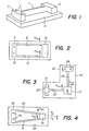
- the purely elastic deformation articulation shown consists of a blade 1, one end of which is connected to a fixed part 2 made integral by means of two screws 3 of a base plate 4 which constitutes the frame of the device, and the other end of which is secured to a movable part 5 which in itself constitutes the movable support of a component or which is secured to the movable support of this component.
- the displacement m of the moving part 5 in the direction of the thickness of the blade is relatively easy thanks to the significant bending of this blade in this coordinate, while the displacement m a according to a direction corresponding to the width of the blade remains small and the displacement m o in a direction corresponding to the length of the blade is negligible.
- the exact value of the elasticities corresponding to these three displacements is given by the following expressions: where E represents the Young's modulus of the material of the blade, F e being the force imposed for example by a micrometric displacement screw, F a depending on the weight of the movable plate and F o being a function of the friction between the parts to position.
- the displacement m o is much smaller than the displacement m e which is particularly important for the independence of the control of the coordinates m o and m e .
- the effect of m a inherently low, becomes negligible when considering its projection in the plan o m m e.
- the displacement modules illustrated in FIGS. 2, 3 and 4 allow displacements at a coordinate in a plane.
- one of the parts to be assembled will be fixed on the mobile support and the other to the base plate or frame and the relative movement of the mobile support will be controlled by a control device. appropriate.
- Fig. 2 shows a device comprising a frame 10 on which is mounted a fixed part 11 which carries two parallel blades 12 and 13 rigidly connected to a part 14 integral with the mobile support or itself constituting this mobile support.
- This type of displacement module will hereinafter be called a translation module .
- the device shown in fig. 3 consists of a base plate or frame 20 carrying two fixed parts 21 and 22 mounted on the frame respectively by means of screws 23 and 24 and each carrying a flexible blade respectively 25 and 26.
- the ends of the blades 25 and 26 not connected to the fixed parts 21 and 22 are connected to a movable plate 27 which itself constitutes the movable support carrying one of the components to be assembled such as for example an optical fiber, or is integral with this support.
- the two blades 25 and 26 are in this case arranged at right angles and their extension is intersected at a point R which defines the intersection of the plane me 25me26 (respectively defining the elastic displacements of the blade 25 and the blade 26) with the axis of rotation of the movable plate 27.
- the center of rotation R is located inside the periphery of the movable plate. However, this center of rotation can be found anywhere else in the plane.
- the two blades 30 and 31 have one end secured to a part 32 fixed for example by two screws 33 to a base plate 34 constituting the frame and their other end connected to a movable plate 35.
- the point of intersection R of the axes of the two blades 30 and 31 is outside the movable plate, and the rotation module thus produced is centered outside the movable plate.
- the translation module defined with reference to FIG. 2 constitutes a particular case of a rotation module in which the center of rotation is rejected endlessly.
- the device according to fig. 5 illustrates more particularly a mechanism for ensuring the movement of at least one of the components relative to the other.
- This device consists of a frame 40 on which is directly mounted a fixed support 41 carrying one of the two components to be assembled.
- a movable plate 42 carries the support 43 of a second part to be positioned relative to the first.
- the joints making it possible to move the movable plate 42 are not shown in this figure.
- the base plate carries on the one hand a micrometric screw device 44 which makes it possible to exert on the movable plate 42 a thrust in the direction of arrow A.
- On the side opposite to the micrometric screw device 44 is mounted a stop with support spring 45.
- This device makes it possible to ensure movement control at a coordinate in a plane for all modules with two joints according to FIGS. 2, 3 and 4.
- FIG. 6 illustrates a device comprising a base plate 50 on which is directly mounted a first fixed part 51 fixed to the base plate by screws 52.
- This fixed part 51 serves to support the ends of two parallel blades 53 and 54 whose other ends are integral with a first movable plate 55.
- the movable plate 55 serves to support a part 56 fixed to the plate 55 by means of screws 57.
- the part 56 carries two blades 58 and 59 whose other ends are integral with a second movable plate 60 which serves to support a parts to be assembled or which is linked to such a support.
- the fixed part 56, the blades 58 and 59 and the second movable plate 60 constitute an elementary module of rotation as described above with reference to FIG. 4.
- a first micrometric screw 61 acts on the translation module and a second micrometric screw 62 acts on the rotation module.
- the other part of the pair of parts to be assembled is preferably directly fixed to the base plate 50.
- Fig. 7 shows a combination of elementary modules arranged in parallel.
- the device comprises a base plate 70 carrying a first fixed block 71 and a second fixed block 72 mounted on the base plate for example by means of screws 73 and 74.
- Each of these two blocks 71 and 72 is integral of two parallel blades 75, 76 and 77, 78 respectively of two translation modules mounted perpendicularly to each other.
- the blades 75 and 76 carry a first movable plate 79 and the blades 77 and 78 carry a second movable plate 80.
- the movable plate 79 carries either directly, or by means of an appropriate support, one of the components to be assembled (not shown) while the movable plate 80 carries, either directly or indirectly via an appropriate support, the second component 81 to be positioned relative to the first.
- Two devices 82 and 83 for micrometric control of the displacements of the two translation modules are mounted on the base plate 70.
- first part that is to say the one which mode relative to the plane of micro-displacements
- second part that is to say that which is mounted in a fixed position in a direction perpendicular to the plane of the micro-displacements, is fixed directly to the support plate. Pressure exerted on the first part perpendicular to the membrane makes it possible to bring the two parts into contact.
- FIGS. 8 and 9 Such a membrane fastening method is represented by FIGS. 8 and 9.
- one of the parts to be assembled 90 constituted for example by an optical fiber embedded in a block of resin, or mounted in a rigid support, is rigidly mounted on a workpiece holder 91.
- This workpiece holder 91 is mounted by gluing, riveting, screwing or any other known means, to a membrane 92 constituted for example by a rectangular piece cut from a sheet of elastic material or by thin blades having relatively high elastic properties depending on their thickness.
- the membrane 92 is assembled by known means to a movable plate 93 which consists, in the example shown, of a rigid U-shaped frame.
- the second part 94 intended to be assembled to the part 90 is integral with the base plate 95.
- An accommodation spring 96 pushes on the central part of the workpiece carrier 91.
- the parts 90 and 94 are fixed respectively to the workpiece holder and to the base plate by gluing, by air depression, if the support surface is sufficient, or by conventional vices. This way of proceeding can have drawbacks due to the fact that the glued parts are difficult to detach or that the vices can constitute bulky parts.
- FIGS. 10, 11 and 12 a second method of gripping the parts illustrated by FIGS. 10, 11 and 12 is proposed, where the membrane and the workpiece holder are replaced by elastic gripping blades, flexible perpendicular to the plane of the micro-displacements. .
- the device shown comprises a first series of gripping blades 100 fixed directly to the support plate 101 with accommodation and a second series of gripping blades 102 fixed to the support plate by means of translation modules with elastic blades 103 and 104, the direction of translation of which is oriented parallel to the gripping blades.
- a clamping spring 105 makes it possible to push the blades of the second series of blades 102 in the direction of the first series of blades 100, in order to block the part to be assembled 106, in the plane of micro-displacements, while retaining the faculty thereof. perpendicular accommodation by the flexibility of the grip blades.
- the other part to be assembled 107 can be gripped by a similar device comprising a first series of gripping blades 100 ', fixed directly to the support plate 101', and a second series of gripping blades 102 ', fixed to the support plate by means of translation modules with elastic blades 103 ′ and 104 ′.
- a clamping spring 105 ' pushes the blades of the second series of blades 102' towards the first series of blades 100 '.
- the gripping blades 100 ′ and 102 ′ are rigid so that this second piece to be assembled 107 is completely blocked on its support plate 101 ′.
- the pressure clamp shown in fig. 12 comprises two jaws 110 and 111 articulated relative to each other around a hinge 112.
- the parts to be assembled 106 and 107 are held by two pressure buffers 113 and 114 made of elastomeric material.
- the two jaws are pushed relative to each other in the closed position, by a compression spring 115.
- This clamp allows contacting of the parts to be assembled. Because it is independent, it also makes it possible, when assembly is carried out, to maintain the parts in their respective positions and to transport the assembly without modifying the relative positions of these parts, outside the micro-machine. trips, to another workstation.
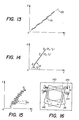
- Fig. 13 illustrates the jerky movement of the part to be positioned relative to the other.
- the jerky advance effect of a mechanical translation system occurs each time a static friction force opposes the movement.
- the micrometric screw is actuated in advance.
- the parts transmitting the advance are stretched elastically under stress. When the latter exceeds the friction resistance threshold, the sliding begins.
- the sliding forces of friction for low speeds of displacement, are lower than the static threshold.
- the tension of the parts transmitting the advance is released and the friction force slows the sliding; soon a new position of equilibrium is reached. So it is fine to actuate the micrometric screw continuously and very slowly, the advance movement of the part to be assembled is done in jerks, jumping from one equilibrium position to the next.
- the displacement instruction X that is to say the advance of the screw at infinitely slow speed, has been plotted on the abscissa X and the effective displacement of the part to be positioned on the ordinate Y.
- the theoretical displacement in the absence of friction is represented by the straight line 130 represented in broken lines and the effective displacement is illustrated by the jerky curve 131.
- the displacement process used in the context of the devices described is based on the observation that the successive equilibrium positions of the jerks are essentially aligned according to the theoretical direction of advance. This phenomenon is due to the fact that the friction results from the contact of a very large number of microscopic asperities of random form; the sum of the components of the forces transmitted by each roughness in the direction perpendicular to the direction of advance is zero, and the jerks are thus made according to the direction of advance.
- oblique translations are combined with respect to this axis.
- fig. 14 The principle of oblique translation is illustrated in fig. 14.
- the theoretical advance is programmed by means of the micrometric screw, to arrive at point P2 of the coordinates X2, Y2. Due to the jerks of the movement of movement, the real point of arrival is P3, of coordinates X3, Y3.
- the advance precision is given by the distance r 2,3 separating P2 from P3.
- the precision along each of the coordinate axes of the XY displacement plane will be given by the expressions: where ⁇ represents the angle ( OX , P1P3 ).
- the total translation P o p m is equal to the sum of the oblique elementary translations.
- the precision is that of an elementary translation, and does not depend on the number of elementary translations since the mean value of the saccade errors is zero (see fig. 13).
- the oblique translations are produced by a device as shown in FIG. 16 comprising a base plate on which are mounted two translation modules 141 and 142 arranged in such a way that their axes form an angle 0 ⁇ between them.
- Each of these modules is associated with a movement control mechanism, for example a micrometric screw, respectively 143 and 144.
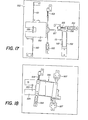
- FIGS. 17 and 18 An example of such a combination is illustrated by FIGS. 17 and 18 illustrating a device comprising various displacement modules and means for allowing the oblique translation of one part with respect to the other.
- This device comprises a base plate 150 on which is mounted a translation module 151 comprising two parallel elastic blades 152 and 153 associated with a movement control mechanism comprising a micrometric screw 154 and a movable stop 155.
- the movable plate 156 of this module carries an elastic blade 157, perpendicular to the blades 151 and 153, and one end of which is fixed to the support plate 158.
- This plate carrying one of the parts 159 to be positioned is also supported by the two elastic blades 160 and 161 which, with the blade 157, form a rotation module controlled by a micrometric screw 162 associated with a movable stop 163.
- L he assembly constitutes a combination of a rotation module and a translation module.
- Fig. 18 shows the upper sub-assembly of this device. It consists of a movable plate 164 carrying the second movable part 165 to be positioned relative to the first. This plate is integral with a translation module 166 mounted on two pivots 167 to facilitate the positioning of parts 159 and 165. This translation module is controlled by a micrometric screw 168 associated with a movable stop 169. It is also mounted obliquely to the lower sub-assembly, to allow oblique translations.
Landscapes
- Physics & Mathematics (AREA)
- General Physics & Mathematics (AREA)
- Optics & Photonics (AREA)
- Mounting And Adjusting Of Optical Elements (AREA)
- Mechanical Coupling Of Light Guides (AREA)
- Cable Accessories (AREA)
- Details Of Measuring And Other Instruments (AREA)
Priority Applications (1)
| Application Number | Priority Date | Filing Date | Title |
|---|---|---|---|
| AT84810467T ATE43186T1 (de) | 1983-10-05 | 1984-09-25 | Verfahren und vorrichtung zur positionierung einer optischen faser bezueglich eines anderen optischen bestandteiles. |
Applications Claiming Priority (2)
| Application Number | Priority Date | Filing Date | Title |
|---|---|---|---|
| FR8315955A FR2553200B1 (fr) | 1983-10-05 | 1983-10-05 | Procede pour positionner une fibre optique par rapport a un autre composant optique, et dispositif pour la mise en oeuvre de ce procede |
| FR8315955 | 1983-10-05 |
Publications (2)
| Publication Number | Publication Date |
|---|---|
| EP0147363A1 true EP0147363A1 (de) | 1985-07-03 |
| EP0147363B1 EP0147363B1 (de) | 1989-05-17 |
Family
ID=9292905
Family Applications (1)
| Application Number | Title | Priority Date | Filing Date |
|---|---|---|---|
| EP84810467A Expired EP0147363B1 (de) | 1983-10-05 | 1984-09-25 | Verfahren und Vorrichtung zur Positionierung einer optischen Faser bezüglich eines anderen optischen Bestandteiles |
Country Status (7)
| Country | Link |
|---|---|
| US (1) | US4615097A (de) |
| EP (1) | EP0147363B1 (de) |
| JP (1) | JPS60101505A (de) |
| AT (1) | ATE43186T1 (de) |
| CA (1) | CA1257956A (de) |
| DE (1) | DE3478253D1 (de) |
| FR (1) | FR2553200B1 (de) |
Cited By (2)
| Publication number | Priority date | Publication date | Assignee | Title |
|---|---|---|---|---|
| GB2194074A (en) * | 1986-08-14 | 1988-02-24 | Photon Control Limited | Rotatable workpiece supports |
| WO1990005317A1 (en) * | 1988-11-10 | 1990-05-17 | Pharmacia Ab | Optical interface means |
Families Citing this family (8)
| Publication number | Priority date | Publication date | Assignee | Title |
|---|---|---|---|---|
| JPH0646246B2 (ja) * | 1984-10-05 | 1994-06-15 | 日本電信電話株式会社 | 微動移動機構 |
| DE3500356A1 (de) * | 1985-01-08 | 1986-07-10 | Philips Patentverwaltung Gmbh, 2000 Hamburg | Vorrichtung zum positionieren eines optischen wellenleiters |
| NL8500615A (nl) * | 1985-03-05 | 1986-10-01 | Nederlanden Staat | Fijninstelmechanisme voor het nauwkeurig positioneren van een instelelement. |
| FR2606890B1 (fr) * | 1986-11-18 | 1989-06-30 | Lyonnaise Transmiss Optiques | Dispositif de deplacement de l'extremite d'une fibre optique suivant deux axes orthogonaux |
| US4840450A (en) * | 1988-02-03 | 1989-06-20 | General Electric Company | Apparatus and method for optical fiber end positioning for laser injection |
| FR2671409B1 (fr) * | 1991-01-08 | 1994-06-10 | Alcatel Fibres Optiques | Microsoudeuse pour fibres optiques et procede de soudage a l'aide de cette microsoudeuse. |
| US7430081B2 (en) * | 2002-02-28 | 2008-09-30 | Emcore Corporation | Sub-micron adjustable mount for supporting a component and method |
| US7126078B2 (en) | 2002-02-28 | 2006-10-24 | Emcore Corporation | Sub-micron adjustable mount for supporting a component and method |
Family Cites Families (7)
| Publication number | Priority date | Publication date | Assignee | Title |
|---|---|---|---|---|
| JPS55105214A (en) * | 1979-02-07 | 1980-08-12 | Ricoh Co Ltd | Fixing device of optical transmission body array |
| JPS56126816A (en) * | 1980-03-10 | 1981-10-05 | Nippon Telegr & Teleph Corp <Ntt> | Position fine adjustment equipment |
| JPS56156812A (en) * | 1980-05-09 | 1981-12-03 | Nippon Telegr & Teleph Corp <Ntt> | Aligning device for optical fiber |
| JPS6024443B2 (ja) * | 1981-02-03 | 1985-06-13 | 日本電信電話株式会社 | 光フアイバ心線のコア軸合せ装置 |
| FR2524654B1 (fr) * | 1982-03-30 | 1985-10-04 | Socapex | Dispositif de raccordement de fibres optiques et procede le mettant en oeuvre |
| EP0100781B1 (de) * | 1982-08-12 | 1986-04-16 | ANT Nachrichtentechnik GmbH | Justagevorrichtung für einen Lichtwellenleiter |
| DE3321988A1 (de) * | 1983-06-18 | 1984-12-20 | Standard Elektrik Lorenz Ag, 7000 Stuttgart | Vorrichtung zur spielfreien verschiebung von objekten in einem koordinatensystem |
-
1983
- 1983-10-05 FR FR8315955A patent/FR2553200B1/fr not_active Expired
-
1984
- 1984-09-25 DE DE8484810467T patent/DE3478253D1/de not_active Expired
- 1984-09-25 EP EP84810467A patent/EP0147363B1/de not_active Expired
- 1984-09-25 AT AT84810467T patent/ATE43186T1/de active
- 1984-10-04 JP JP59209020A patent/JPS60101505A/ja active Pending
- 1984-10-04 CA CA000464784A patent/CA1257956A/fr not_active Expired
- 1984-10-05 US US06/658,298 patent/US4615097A/en not_active Expired - Fee Related
Non-Patent Citations (2)
| Title |
|---|
| PATENTS ABSTRACTS OF JAPAN, vol. 6, no. 2 (P-96)[880], 8 janvier 1982; & JP-A-56 126 816 (NIPPON DENSHIN DENWA KOSHA) 05-10-1981 * |
| PATENTS ABSTRACTS OF JAPAN, vol. 6, no. 225 (P-154)[1103], 10 novembre 1982; & JP-A-57 129 403 (NIPPON DENSHIN DENWA KOSHA) 11-08-1982 * |
Cited By (4)
| Publication number | Priority date | Publication date | Assignee | Title |
|---|---|---|---|---|
| GB2194074A (en) * | 1986-08-14 | 1988-02-24 | Photon Control Limited | Rotatable workpiece supports |
| GB2194074B (en) * | 1986-08-14 | 1990-02-14 | Photon Control Limited | Workpiece supports |
| WO1990005317A1 (en) * | 1988-11-10 | 1990-05-17 | Pharmacia Ab | Optical interface means |
| US5164589A (en) * | 1988-11-10 | 1992-11-17 | Pharmacia Biosensor Ab | Reusable optical interface for non-permanent passive light coupling |
Also Published As
| Publication number | Publication date |
|---|---|
| DE3478253D1 (en) | 1989-06-22 |
| EP0147363B1 (de) | 1989-05-17 |
| JPS60101505A (ja) | 1985-06-05 |
| US4615097A (en) | 1986-10-07 |
| FR2553200B1 (fr) | 1985-12-06 |
| ATE43186T1 (de) | 1989-06-15 |
| FR2553200A1 (fr) | 1985-04-12 |
| CA1257956A (fr) | 1989-08-01 |
Similar Documents
| Publication | Publication Date | Title |
|---|---|---|
| EP0840023B1 (de) | Flexibles planares Gelenk mit einzelnen, monolithischen Modulen | |
| EP0222652B1 (de) | Kraft- und Torsionsmessvorrichtung und ihre Anwendung an einer Fühler- oder Greifeinrichtung | |
| EP0147363B1 (de) | Verfahren und Vorrichtung zur Positionierung einer optischen Faser bezüglich eines anderen optischen Bestandteiles | |
| EP0005792B1 (de) | Verfahren zum Verbinden von optischen Fasern, die bandförmig in einem Kabel angeordnet sind und Vorrichtung zur Durchführung dieses Verfahrens | |
| CA1307957C (fr) | Dispositif de deplacement de l'extremite d'une fibre optique suivant deux axes orthogonaux | |
| FR2677285A1 (fr) | Tete de soudage a laser. | |
| EP0779505B1 (de) | Vorrichtung zur ausseraxialen Prüfung von anisotropen Materialien | |
| EP0218546A1 (de) | Vorrichtung für die Mikropositionierung | |
| CH672182A5 (de) | ||
| EP0029383B1 (de) | Vorrichtung zum Zusammenfügen der Enden optischer Fasern | |
| EP0566511B1 (de) | Vorrichtung zum schrägen Schneiden von einer oder mehreren optischen Fasern | |
| EP1402992A1 (de) | Vorrichtung mit höher Präzision zum Vorgeben oder zum Messen einer Position oder Kraft | |
| EP0121460A1 (de) | Aufnahmestück für optische Fasern für eine Kupplungsvorrichtung und Verfahren zur Herstellung einer solchen Vorrichtung | |
| FR2529333A1 (fr) | Poignet a detection de six composantes d'effort | |
| CH684217A5 (fr) | Procédé et dispositif pour aligner des fibres optiques. | |
| WO1999061884A1 (fr) | Outillage de montage sur une machine de test de traction de deux elements colles l'un a l'autre | |
| EP0177744A1 (de) | Messkopf zur Diametermessung von zylindrischen Objekten | |
| EP0155861B1 (de) | Mechanische Positionseinstellvorrichtung und optische Einstellplatte die diese verwendet | |
| EP0403354B1 (de) | Führungsvorrichtung für ein mobiles Element parallel zu einer Achse und Instrument mit einer derartigen Führung | |
| CH677835A5 (en) | Alignment of optical fibres during parameter measurement | |
| FR2733048A1 (fr) | Dispositif de mesure de deformations d'une eprouvette soumise a un essai de cisaillement | |
| EP0297449A1 (de) | Messfühler für Objektdimensionsmessung | |
| EP4392691B1 (de) | Vorrichtung und verfahren zur positionierung eines optischen instruments | |
| EP2365369A1 (de) | Betätigungssystem für bewegliche Elemente mit relativen, dynamisch kompensierten Bewegungen und Gegenbewegungen | |
| EP0287474A1 (de) | Vorrichtung zum Brechen einer optischen Faser |
Legal Events
| Date | Code | Title | Description |
|---|---|---|---|
| PUAI | Public reference made under article 153(3) epc to a published international application that has entered the european phase |
Free format text: ORIGINAL CODE: 0009012 |
|
| AK | Designated contracting states |
Designated state(s): AT BE CH DE FR GB IT LI LU NL SE |
|
| RHK1 | Main classification (correction) |
Ipc: G02B 6/42 |
|
| 17P | Request for examination filed |
Effective date: 19851204 |
|
| 17Q | First examination report despatched |
Effective date: 19870421 |
|
| GRAA | (expected) grant |
Free format text: ORIGINAL CODE: 0009210 |
|
| AK | Designated contracting states |
Kind code of ref document: B1 Designated state(s): AT BE CH DE FR GB IT LI LU NL SE |
|
| PG25 | Lapsed in a contracting state [announced via postgrant information from national office to epo] |
Ref country code: SE Effective date: 19890517 Ref country code: NL Effective date: 19890517 Ref country code: IT Free format text: LAPSE BECAUSE OF FAILURE TO SUBMIT A TRANSLATION OF THE DESCRIPTION OR TO PAY THE FEE WITHIN THE PRESCRIBED TIME-LIMIT;WARNING: LAPSES OF ITALIAN PATENTS WITH EFFECTIVE DATE BEFORE 2007 MAY HAVE OCCURRED AT ANY TIME BEFORE 2007. THE CORRECT EFFECTIVE DATE MAY BE DIFFERENT FROM THE ONE RECORDED. Effective date: 19890517 Ref country code: AT Effective date: 19890517 |
|
| REF | Corresponds to: |
Ref document number: 43186 Country of ref document: AT Date of ref document: 19890615 Kind code of ref document: T |
|
| REF | Corresponds to: |
Ref document number: 3478253 Country of ref document: DE Date of ref document: 19890622 |
|
| GBT | Gb: translation of ep patent filed (gb section 77(6)(a)/1977) | ||
| PG25 | Lapsed in a contracting state [announced via postgrant information from national office to epo] |
Ref country code: LU Free format text: LAPSE BECAUSE OF NON-PAYMENT OF DUE FEES Effective date: 19890930 Ref country code: BE Effective date: 19890930 |
|
| NLV1 | Nl: lapsed or annulled due to failure to fulfill the requirements of art. 29p and 29m of the patents act | ||
| PLBE | No opposition filed within time limit |
Free format text: ORIGINAL CODE: 0009261 |
|
| STAA | Information on the status of an ep patent application or granted ep patent |
Free format text: STATUS: NO OPPOSITION FILED WITHIN TIME LIMIT |
|
| BERE | Be: lapsed |
Owner name: FONDATION SUISSE POUR LA RECHERCHE EN MICROTECHNI Effective date: 19890930 Owner name: S.A. CABLOPTIC Effective date: 19890930 |
|
| 26N | No opposition filed | ||
| PGFP | Annual fee paid to national office [announced via postgrant information from national office to epo] |
Ref country code: DE Payment date: 19900915 Year of fee payment: 7 |
|
| PGFP | Annual fee paid to national office [announced via postgrant information from national office to epo] |
Ref country code: GB Payment date: 19900924 Year of fee payment: 7 |
|
| PGFP | Annual fee paid to national office [announced via postgrant information from national office to epo] |
Ref country code: FR Payment date: 19900926 Year of fee payment: 7 |
|
| PGFP | Annual fee paid to national office [announced via postgrant information from national office to epo] |
Ref country code: CH Payment date: 19901005 Year of fee payment: 7 |
|
| PG25 | Lapsed in a contracting state [announced via postgrant information from national office to epo] |
Ref country code: GB Effective date: 19910925 |
|
| PG25 | Lapsed in a contracting state [announced via postgrant information from national office to epo] |
Ref country code: LI Effective date: 19910930 Ref country code: CH Effective date: 19910930 |
|
| GBPC | Gb: european patent ceased through non-payment of renewal fee | ||
| PG25 | Lapsed in a contracting state [announced via postgrant information from national office to epo] |
Ref country code: FR Effective date: 19920529 |
|
| REG | Reference to a national code |
Ref country code: CH Ref legal event code: PL |
|
| PG25 | Lapsed in a contracting state [announced via postgrant information from national office to epo] |
Ref country code: DE Effective date: 19920602 |
|
| REG | Reference to a national code |
Ref country code: FR Ref legal event code: ST |