EP0029577A1 - Echangeur de chaleur pour le refroidissement sans poussières d'une armoire comprenant un appareillage électrique - Google Patents
Echangeur de chaleur pour le refroidissement sans poussières d'une armoire comprenant un appareillage électrique Download PDFInfo
- Publication number
- EP0029577A1 EP0029577A1 EP80107173A EP80107173A EP0029577A1 EP 0029577 A1 EP0029577 A1 EP 0029577A1 EP 80107173 A EP80107173 A EP 80107173A EP 80107173 A EP80107173 A EP 80107173A EP 0029577 A1 EP0029577 A1 EP 0029577A1
- Authority
- EP
- European Patent Office
- Prior art keywords
- plates
- package
- plate
- heat exchanger
- electronic circuit
- Prior art date
- Legal status (The legal status is an assumption and is not a legal conclusion. Google has not performed a legal analysis and makes no representation as to the accuracy of the status listed.)
- Granted
Links
- 238000001816 cooling Methods 0.000 title claims abstract description 19
- 239000003570 air Substances 0.000 abstract 3
- 239000012080 ambient air Substances 0.000 abstract 3
- 238000005452 bending Methods 0.000 description 5
- 239000002184 metal Substances 0.000 description 5
- 238000009423 ventilation Methods 0.000 description 3
- 238000004140 cleaning Methods 0.000 description 2
- 238000010276 construction Methods 0.000 description 1
- 239000002826 coolant Substances 0.000 description 1
- 238000007791 dehumidification Methods 0.000 description 1
- 239000003292 glue Substances 0.000 description 1
- 238000010438 heat treatment Methods 0.000 description 1
- NLYAJNPCOHFWQQ-UHFFFAOYSA-N kaolin Chemical compound O.O.O=[Al]O[Si](=O)O[Si](=O)O[Al]=O NLYAJNPCOHFWQQ-UHFFFAOYSA-N 0.000 description 1
- 238000007789 sealing Methods 0.000 description 1
- 238000003466 welding Methods 0.000 description 1
Images


Classifications
-
- H—ELECTRICITY
- H05—ELECTRIC TECHNIQUES NOT OTHERWISE PROVIDED FOR
- H05K—PRINTED CIRCUITS; CASINGS OR CONSTRUCTIONAL DETAILS OF ELECTRIC APPARATUS; MANUFACTURE OF ASSEMBLAGES OF ELECTRICAL COMPONENTS
- H05K7/00—Constructional details common to different types of electric apparatus
- H05K7/20—Modifications to facilitate cooling, ventilating, or heating
- H05K7/20536—Modifications to facilitate cooling, ventilating, or heating for racks or cabinets of standardised dimensions, e.g. electronic racks for aircraft or telecommunication equipment
- H05K7/206—Air circulating in closed loop within cabinets wherein heat is removed through air-to-air heat-exchanger
Definitions
- the invention relates to a dust-free cooling of a control cabinet by means of cooling air conveyed by fans and arranged on the outside of the cabinet wall with flat heat exchangers assigned to the one passing through the control cabinet cooling air circuit, between which flat channels belonging to the other cooling air circuit connected to the outside air are heat-transferring are arranged.
- a heat exchanger of the above type in which a side wall or a door consists of a meandering sheet, so that channels for the coolant are formed, which are otherwise separated by the meandering sheet , so that dust-free cooling is possible for the components arranged inside the electronics cabinet.
- the channels formed by the meandering sheet are not closed, so that the air is always out along the way through the folds can escape, which does not result in a particularly good air flow.
- a meandering sheet is very difficult to produce with the required accuracy if the individual folds are bent one after the other.
- a heat exchanger which is surrounded on all sides by a housing, preferably for an air dehumidification system, has also become known, in which the channels of the heat exchanger are formed from identical plates which are assembled into a package and have raised lateral edges and a raised edge on one end face (DE-GM 1 860 641). On the lateral edges of the plates, recesses are provided in the vicinity of the front edge of the plates. The successive plates of the package are aligned opposite to each other in such a way that the lateral recesses of successive plates come to rest at a different end of the heat exchanger.
- the plate pack is arranged in a housing which is closed on all sides and from which the air flows from both sides through the lateral recesses into the bent plates which form the first heat zone.
- the air reaches an evaporator, from which it goes into another Part of the housing flows in, from which it in turn passes through the lateral recesses into the channels of the second heating zone, whereupon it leaves the heat exchanger dehumidified.
- this known heat exchanger one and the same air flow is therefore influenced in terms of heat. Since it is surrounded on all sides by a housing, the cleaning and assembly of the panels that make it up with the raised edges is made more difficult.
- the object of the invention is to provide a heat exchanger for dust-free air cooling of control cabinets, which is easily accessible with a simple construction during assembly and cleaning on the control cabinet and which takes up as little space as possible on the control cabinet.
- the heat exchanger according to the invention is characterized by the features of the patent claim.
- Figure 1 is a heat exchanger 1 for two cooling. air circuits shown, which is used for dust-free air cooling of a control cabinet.
- a box 3 provided with the connection to the outside air producing ventilation slots 2, in which two fans 4 and 5 indicated by dashed lines are arranged.
- a further box 6 On the lower end face of the heat exchanger 1 there is a further box 6, in which two fans 7 and 8, indicated by dashed lines, are also contained.
- the lower box 6 has an opening 9 which, however, points in the opposite direction to the ventilation slots 2 of the upper box 3 and establishes the connection with the interior of the control cabinet.
- the heat exchanger 1 is formed by channels 10a and 10b arranged alternately next to one another.
- the channels 10a are open towards the top of the box 3 and closed towards the bottom of the box 6 at 12, while at this end they have a lateral opening 13 through which the fans 4 and 5 enter the channels 10a blown air can return to the outside air.
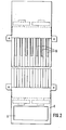
- the channels 10b are closed at their end in the box 3 at 14 and, as shown in FIG. 2, contain lateral openings 15 pointing rearward into the control cabinet, while they are open at the end in the box 6. In this way, the air blown into the ducts 10b by the fans 7 and 8 of the lower box 6 can exit into the control cabinet via the openings 15.
- the channels 10a and 10b are each formed by plates 20, which consist of a base 21 and two laterally bent edges 22 and 23, on which inwardly directed strips 24 and 25 are molded.
- the edge 23 is shortened at one end of the plate 20, so that a recess 26 is formed, which in turn the when the individual plates are assembled opening 13 or 15 forms.
- each of the plates 20 is provided with an end edge 27 which also carries a bent strip 28.
- the plate 20b When assembling the heat exchanger 1, the plate 20b is arranged on the plate 20a, the recess 26 of which is at the top, in such a way that its bottom 21b comes to rest on the strips 24, 25 of the bent edges 22, 23. The recess 26 of the plate 20b is at the bottom.
- the plate 20c which in turn has the same orientation as the plate 20a, is placed on the plate 20b. If larger powers have to be dissipated, further plates 20 can be arranged alternately with the recesses 26 above or below. The last plate still curved, in FIG. 3 plate 20c, is closed off by a simple flat plate 30.
- the alternating arrangement of the plates 20 results in the channels 10a and 10b of the heat exchanger 1, which are each delimited by the raised edges 22 and 23 and the bottom 21 of a plate 20 and the bottom 21 of the adjacent plate 20.
- the alternating arrangement of the plates 20 results in the channels 10a and 10b, which are open at the top and bottom, for the separate cooling air flows.
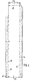
- FIG. 4 shows a sheet metal blank in the form of a sheet metal strip 40 with bending lines 41, 42, 43, 44, from which the plates 20 required for the heat exchanger 1 are made.
- the metal strip 40 By bending the metal strip 40 along the bending lines 41 and 42, the raised edges 22 and 23 are formed; the bent strips 24 and 25 are formed by further folding along the bending lines 43 and 44, while the frontal edge of the respective channel is produced by folding along the bending lines 45 and 46.
- 40 holes 47 are made in the sheet metal strip, through which later draw bolts lead, which hold the individual plates 20 of the heat exchanger 1 together.
- tension bolts which connect the individual plates to each other, they may also be non-releasably connected by welding or K live. It is also possible to glue the plates 20, which are made of plastic, for example, in order to improve the tightness.
Landscapes
- Engineering & Computer Science (AREA)
- Aviation & Aerospace Engineering (AREA)
- Physics & Mathematics (AREA)
- Thermal Sciences (AREA)
- Microelectronics & Electronic Packaging (AREA)
- Cooling Or The Like Of Electrical Apparatus (AREA)
- Heat-Exchange Devices With Radiators And Conduit Assemblies (AREA)
- Separation By Low-Temperature Treatments (AREA)
- Fuel Cell (AREA)
Priority Applications (1)
| Application Number | Priority Date | Filing Date | Title |
|---|---|---|---|
| AT80107173T ATE3178T1 (de) | 1979-11-27 | 1980-11-19 | Zur staubfreien kuehlung eines schaltschrankes dienender waermetauscher. |
Applications Claiming Priority (2)
| Application Number | Priority Date | Filing Date | Title |
|---|---|---|---|
| DE2947687 | 1979-11-27 | ||
| DE2947687A DE2947687C2 (de) | 1979-11-27 | 1979-11-27 | Wärmetauscher |
Publications (2)
| Publication Number | Publication Date |
|---|---|
| EP0029577A1 true EP0029577A1 (fr) | 1981-06-03 |
| EP0029577B1 EP0029577B1 (fr) | 1983-04-27 |
Family
ID=6086963
Family Applications (1)
| Application Number | Title | Priority Date | Filing Date |
|---|---|---|---|
| EP80107173A Expired EP0029577B1 (fr) | 1979-11-27 | 1980-11-19 | Echangeur de chaleur pour le refroidissement sans poussières d'une armoire comprenant un appareillage électrique |
Country Status (5)
| Country | Link |
|---|---|
| EP (1) | EP0029577B1 (fr) |
| JP (1) | JPS5836520B2 (fr) |
| AT (1) | ATE3178T1 (fr) |
| AU (1) | AU540875B2 (fr) |
| DE (1) | DE2947687C2 (fr) |
Cited By (8)
| Publication number | Priority date | Publication date | Assignee | Title |
|---|---|---|---|---|
| EP0111690A1 (fr) * | 1982-11-24 | 1984-06-27 | International Business Machines Corporation | Système de refroidissement avec fluide réfrigérant à contre-courant |
| EP0228470A4 (fr) * | 1985-06-15 | 1987-10-08 | Fanuc Ltd | Echangeur de chaleur. |
| AT384343B (de) * | 1985-04-16 | 1987-10-27 | Siemens Ag Oesterreich | Gehaeuseanordnung fuer belueftete geraete, vorzugsweise der leistungselektronik |
| EP0234550A3 (en) * | 1986-02-27 | 1989-04-12 | Autz+Herrmann | Heat-exchanger element |
| DE3805005A1 (de) * | 1988-02-18 | 1989-08-31 | Krupp Gmbh | Energieversorgungseinrichtung fuer einen reisezugwagen |
| GB2250640A (en) * | 1990-11-29 | 1992-06-10 | Marconi Gec Ltd | A housing arrangement for electrical apparatus |
| DE102018220741B3 (de) * | 2018-11-30 | 2020-04-23 | Siemens Mobility GmbH | Vorrichtung zur Wärmeabfuhr für ein Schienenfahrzeug und Schienenfahrzeug |
| CN115395377A (zh) * | 2022-10-26 | 2022-11-25 | 国网安徽省电力有限公司超高压分公司 | 一种防凝露开关柜柜体 |
Families Citing this family (9)
| Publication number | Priority date | Publication date | Assignee | Title |
|---|---|---|---|---|
| DE3045326C2 (de) * | 1980-12-02 | 1982-10-21 | Autz & Hermann, 6900 Heidelberg | Zur staubfreien Kühlung eines Schaltschrankes dienender Wärmetauscher |
| DE3314870C1 (de) * | 1983-04-25 | 1984-08-02 | Siemens AG, 1000 Berlin und 8000 München | Wärmeaustauscher für einen Elektronikschrank |
| DE3405243C2 (de) * | 1984-02-15 | 1985-12-12 | Autz & Herrmann, 6900 Heidelberg | Einschub-Kühlgerät für Schaltschränke |
| JPS60149025U (ja) * | 1984-03-14 | 1985-10-03 | エスエムケイ株式会社 | 押釦スイツチの防塵構造 |
| AU646283B2 (en) * | 1990-09-05 | 1994-02-17 | Alcatel Australia Limited | Thermally controlled equipment housing |
| DE4134429C1 (en) * | 1991-10-18 | 1993-03-11 | Schroff Gmbh, 7541 Straubenhardt, De | Heat sink device for electronic cabinet - uses counterflow heat exchanger with vertical flow channels for cooling air stream and ambient air. |
| DE29906658U1 (de) | 1999-04-15 | 1999-07-15 | H.-J. Bernstein GmbH, 32479 Hille | Gehäuse zur Aufnahme elektrischer oder elektronischer Bauteile |
| DE102008036755A1 (de) * | 2008-08-07 | 2010-02-11 | Baldwin Germany Gmbh | Schaltschrank |
| IT202100027125A1 (it) | 2021-10-21 | 2023-04-21 | Caffe Toscano S R L | Capsula per la preparazione di caffe’ o bevande solubili |
Citations (3)
| Publication number | Priority date | Publication date | Assignee | Title |
|---|---|---|---|---|
| US2820616A (en) * | 1952-09-03 | 1958-01-21 | Emerson E Nabal | Pressurized electronic case |
| US3559728A (en) * | 1968-11-29 | 1971-02-02 | Kooltronic Fan Co | Electronic equipment rack temperature control |
| DE2006759A1 (de) * | 1970-02-14 | 1971-08-26 | Siemens Ag | Elektromkschrank |
Family Cites Families (2)
| Publication number | Priority date | Publication date | Assignee | Title |
|---|---|---|---|---|
| CH376944A (de) * | 1960-03-28 | 1964-04-30 | Luwa Ag | Wärmeaustauscher |
| DE2231469A1 (de) * | 1972-06-27 | 1974-03-07 | Siemens Ag | Waermeaustauscher fuer einen elektronikschrank |
-
1979
- 1979-11-27 DE DE2947687A patent/DE2947687C2/de not_active Expired
-
1980
- 1980-11-19 AT AT80107173T patent/ATE3178T1/de not_active IP Right Cessation
- 1980-11-19 EP EP80107173A patent/EP0029577B1/fr not_active Expired
- 1980-11-25 AU AU64676/80A patent/AU540875B2/en not_active Ceased
- 1980-11-27 JP JP55167344A patent/JPS5836520B2/ja not_active Expired
Patent Citations (3)
| Publication number | Priority date | Publication date | Assignee | Title |
|---|---|---|---|---|
| US2820616A (en) * | 1952-09-03 | 1958-01-21 | Emerson E Nabal | Pressurized electronic case |
| US3559728A (en) * | 1968-11-29 | 1971-02-02 | Kooltronic Fan Co | Electronic equipment rack temperature control |
| DE2006759A1 (de) * | 1970-02-14 | 1971-08-26 | Siemens Ag | Elektromkschrank |
Cited By (9)
| Publication number | Priority date | Publication date | Assignee | Title |
|---|---|---|---|---|
| EP0111690A1 (fr) * | 1982-11-24 | 1984-06-27 | International Business Machines Corporation | Système de refroidissement avec fluide réfrigérant à contre-courant |
| AT384343B (de) * | 1985-04-16 | 1987-10-27 | Siemens Ag Oesterreich | Gehaeuseanordnung fuer belueftete geraete, vorzugsweise der leistungselektronik |
| EP0228470A4 (fr) * | 1985-06-15 | 1987-10-08 | Fanuc Ltd | Echangeur de chaleur. |
| EP0234550A3 (en) * | 1986-02-27 | 1989-04-12 | Autz+Herrmann | Heat-exchanger element |
| DE3805005A1 (de) * | 1988-02-18 | 1989-08-31 | Krupp Gmbh | Energieversorgungseinrichtung fuer einen reisezugwagen |
| GB2250640A (en) * | 1990-11-29 | 1992-06-10 | Marconi Gec Ltd | A housing arrangement for electrical apparatus |
| GB2250640B (en) * | 1990-11-29 | 1994-10-05 | Marconi Gec Ltd | A housing arrangement for electrical apparatus |
| DE102018220741B3 (de) * | 2018-11-30 | 2020-04-23 | Siemens Mobility GmbH | Vorrichtung zur Wärmeabfuhr für ein Schienenfahrzeug und Schienenfahrzeug |
| CN115395377A (zh) * | 2022-10-26 | 2022-11-25 | 国网安徽省电力有限公司超高压分公司 | 一种防凝露开关柜柜体 |
Also Published As
| Publication number | Publication date |
|---|---|
| AU540875B2 (en) | 1984-12-06 |
| ATE3178T1 (de) | 1983-05-15 |
| JPS5836520B2 (ja) | 1983-08-09 |
| JPS56138996A (en) | 1981-10-29 |
| EP0029577B1 (fr) | 1983-04-27 |
| DE2947687A1 (de) | 1981-09-17 |
| DE2947687C2 (de) | 1983-01-27 |
| AU6467680A (en) | 1981-06-04 |
Similar Documents
| Publication | Publication Date | Title |
|---|---|---|
| EP0029577B1 (fr) | Echangeur de chaleur pour le refroidissement sans poussières d'une armoire comprenant un appareillage électrique | |
| DE3045326C2 (de) | Zur staubfreien Kühlung eines Schaltschrankes dienender Wärmetauscher | |
| DE69200834T3 (de) | Ölradiator, insbesondere für Raumheizung. | |
| DE3336049C3 (de) | Gegenstrom-Wärmetauscher | |
| DE19846518A1 (de) | Wärmetauscher, insbesondere für Gase und Flüssigkeiten | |
| DE3437259C2 (fr) | ||
| DE68922245T2 (de) | Luftkasten mit drei Teilströmen. | |
| EP0121163B1 (fr) | Echangeur de chaleur pour armoire électronique | |
| DE2951352C2 (de) | Flachrohr-Wärmetauscher | |
| DE3423736A1 (de) | Kreuzstrom-plattenwaermetauscher | |
| DE2231469A1 (de) | Waermeaustauscher fuer einen elektronikschrank | |
| DE10033449A1 (de) | Werkzeugkasten | |
| DE19737531C2 (de) | Wärmetauscherbausatz und Klimatisierungsmeßgerät | |
| DE1860641U (de) | Waermeaustauscher. | |
| EP0414021A2 (fr) | Sortie inductive | |
| DE19804905A1 (de) | Schaltschrank | |
| DE3507255A1 (de) | Gehaeuse fuer elektrische bauteile | |
| EP0178465A1 (fr) | Dispositif de refroidissement du type à tiroir pour des armoires de distribution | |
| EP1770345B1 (fr) | Réseau d'échange de chaleur et échangeur de chaleur comprenant celui-ci | |
| CH657693A5 (de) | Lueftungsvorrichtung fuer einen raum mit zwei getrennten stroemungswegen zur belueftung und entlueftung. | |
| DE2928027A1 (de) | Gehaeuselose elektrische maschine | |
| DE3606334C2 (fr) | ||
| DE9001929U1 (de) | Lüftereinschub zum Abführen der Verlustwärme von elektrischen Bauteilen und Baugruppen | |
| DE19816623C2 (de) | Spritzwandmodul und aus Spritzwandmodulen aufgebaute Spritzwand | |
| EP0663580A1 (fr) | Echangeur de Chaleur, en particulier évaporateur |
Legal Events
| Date | Code | Title | Description |
|---|---|---|---|
| PUAI | Public reference made under article 153(3) epc to a published international application that has entered the european phase |
Free format text: ORIGINAL CODE: 0009012 |
|
| AK | Designated contracting states |
Designated state(s): AT BE CH FR GB IT LU NL SE |
|
| 17P | Request for examination filed |
Effective date: 19810918 |
|
| ITF | It: translation for a ep patent filed | ||
| GRAA | (expected) grant |
Free format text: ORIGINAL CODE: 0009210 |
|
| AK | Designated contracting states |
Designated state(s): AT BE CH FR GB IT LI LU NL SE |
|
| REF | Corresponds to: |
Ref document number: 3178 Country of ref document: AT Date of ref document: 19830515 Kind code of ref document: T |
|
| ET | Fr: translation filed | ||
| PGFP | Annual fee paid to national office [announced via postgrant information from national office to epo] |
Ref country code: GB Payment date: 19911015 Year of fee payment: 12 |
|
| PGFP | Annual fee paid to national office [announced via postgrant information from national office to epo] |
Ref country code: AT Payment date: 19911018 Year of fee payment: 12 |
|
| PGFP | Annual fee paid to national office [announced via postgrant information from national office to epo] |
Ref country code: FR Payment date: 19911022 Year of fee payment: 12 |
|
| PGFP | Annual fee paid to national office [announced via postgrant information from national office to epo] |
Ref country code: LU Payment date: 19911024 Year of fee payment: 12 |
|
| PGFP | Annual fee paid to national office [announced via postgrant information from national office to epo] |
Ref country code: SE Payment date: 19911112 Year of fee payment: 12 |
|
| PGFP | Annual fee paid to national office [announced via postgrant information from national office to epo] |
Ref country code: BE Payment date: 19911127 Year of fee payment: 12 |
|
| PGFP | Annual fee paid to national office [announced via postgrant information from national office to epo] |
Ref country code: CH Payment date: 19911128 Year of fee payment: 12 |
|
| ITTA | It: last paid annual fee | ||
| PGFP | Annual fee paid to national office [announced via postgrant information from national office to epo] |
Ref country code: NL Payment date: 19911130 Year of fee payment: 12 |
|
| EPTA | Lu: last paid annual fee | ||
| PG25 | Lapsed in a contracting state [announced via postgrant information from national office to epo] |
Ref country code: LU Free format text: LAPSE BECAUSE OF NON-PAYMENT OF DUE FEES Effective date: 19921119 Ref country code: GB Effective date: 19921119 Ref country code: AT Effective date: 19921119 |
|
| PG25 | Lapsed in a contracting state [announced via postgrant information from national office to epo] |
Ref country code: SE Effective date: 19921120 |
|
| PG25 | Lapsed in a contracting state [announced via postgrant information from national office to epo] |
Ref country code: LI Effective date: 19921130 Ref country code: CH Effective date: 19921130 Ref country code: BE Effective date: 19921130 |
|
| BERE | Be: lapsed |
Owner name: AUTZ + HERRMANN METALLWAREN- UND MASCHINENFABRIK Effective date: 19921130 |
|
| PG25 | Lapsed in a contracting state [announced via postgrant information from national office to epo] |
Ref country code: NL Effective date: 19930601 |
|
| GBPC | Gb: european patent ceased through non-payment of renewal fee |
Effective date: 19921119 |
|
| NLV4 | Nl: lapsed or anulled due to non-payment of the annual fee | ||
| PG25 | Lapsed in a contracting state [announced via postgrant information from national office to epo] |
Ref country code: FR Effective date: 19930730 |
|
| REG | Reference to a national code |
Ref country code: CH Ref legal event code: PL |
|
| REG | Reference to a national code |
Ref country code: FR Ref legal event code: ST |
|
| EUG | Se: european patent has lapsed |
Ref document number: 80107173.9 Effective date: 19930610 |
|
| PLBE | No opposition filed within time limit |
Free format text: ORIGINAL CODE: 0009261 |
|
| STAA | Information on the status of an ep patent application or granted ep patent |
Free format text: STATUS: NO OPPOSITION FILED WITHIN TIME LIMIT |