EP0030228A2 - Circuits de parole pour appareils téléphoniques - Google Patents
Circuits de parole pour appareils téléphoniques Download PDFInfo
- Publication number
- EP0030228A2 EP0030228A2 EP81100846A EP81100846A EP0030228A2 EP 0030228 A2 EP0030228 A2 EP 0030228A2 EP 81100846 A EP81100846 A EP 81100846A EP 81100846 A EP81100846 A EP 81100846A EP 0030228 A2 EP0030228 A2 EP 0030228A2
- Authority
- EP
- European Patent Office
- Prior art keywords
- circuit
- transistor
- receiver
- transmitter
- signal
- Prior art date
- Legal status (The legal status is an assumption and is not a legal conclusion. Google has not performed a legal analysis and makes no representation as to the accuracy of the status listed.)
- Withdrawn
Links
Images
Classifications
-
- H—ELECTRICITY
- H04—ELECTRIC COMMUNICATION TECHNIQUE
- H04M—TELEPHONIC COMMUNICATION
- H04M1/00—Substation equipment, e.g. for use by subscribers
- H04M1/58—Anti-side-tone circuits
- H04M1/585—Anti-side-tone circuits implemented without inductive element
-
- H—ELECTRICITY
- H04—ELECTRIC COMMUNICATION TECHNIQUE
- H04M—TELEPHONIC COMMUNICATION
- H04M1/00—Substation equipment, e.g. for use by subscribers
- H04M1/60—Substation equipment, e.g. for use by subscribers including speech amplifiers
- H04M1/6025—Substation equipment, e.g. for use by subscribers including speech amplifiers implemented as integrated speech networks
-
- H—ELECTRICITY
- H04—ELECTRIC COMMUNICATION TECHNIQUE
- H04M—TELEPHONIC COMMUNICATION
- H04M1/00—Substation equipment, e.g. for use by subscribers
- H04M1/738—Interface circuits for coupling substations to external telephone lines
- H04M1/76—Compensating for differences in line impedance
-
- H—ELECTRICITY
- H04—ELECTRIC COMMUNICATION TECHNIQUE
- H04M—TELEPHONIC COMMUNICATION
- H04M9/00—Arrangements for interconnection not involving centralised switching
- H04M9/08—Two-way loud-speaking telephone systems with means for conditioning the signal, e.g. for suppressing echoes for one or both directions of traffic
- H04M9/10—Two-way loud-speaking telephone systems with means for conditioning the signal, e.g. for suppressing echoes for one or both directions of traffic with switching of direction of transmission by voice frequency
Definitions
- This application relates generally to speech networks for telephone sets, and is a divided-out application from European Patent Application No.80303044.4.
- the impedance of the set is matched (by varistor networks built into the set) to that of the transmission line by drawing relatively high telephone set currents (such as 150ma) on short loops and relatively low currents (such as 20ma) on long loops.
- Such networks are inherently passive (no gain), and cannot boost transmitted signal level or increase receive sensitivity.
- the present invention provides a speech network for a telephone set having a receiver circuit and a transmitter circuit connected between tip and ring leads connected to a telephone line, a transistor circuit connected between the tip and ring leads for amplifying speech signals, and a first circuit for normally connecting the transistor circuit between the tip and ring leads in a first configuration or receive mode for amplifying a received signal from the line and for applying the amplified receive signal to the receiver circuits, and is characterised in that a second circuit is provided for connecting the transistor circuit in a second and different configuration or transmit mode, for amplification of the transmitter output by the transistor circuit and transmission of the amplified transmit signal to the line, and in that a switching means is provided coupled to be actuated by a signal from the transmitter circuit for switching the transistor circuit from the first configuration to the second configuration in response to a transmitter output signal above a predetermined threshold level.
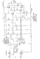
- FIGURE is a circuit diagram of a speech network for an electronic telephone set, in accordance with one specific embodiment of the invention.
- the speech network 11 includes a conventional telephone receiver 27 and a conventional transmitter 60 connected in parallel between a "tip" lead 16 (designated “tip-2") and a "ring” lead 17 by an R-C network including resistors R23-R32 and capacitors C8-C12, arranged as shown, and by a set of three transistors Q4, Q5, Q6 that are selectively operated by a switching unit or controller 40, as will be described.
- the network 11 is used in conjunction with a circuit 10 for automatically initializing the loop current of the set at a desired level, such as 20-25ma as is described in the aforementioned European Patent Application No . 80303044.4 from which the present application is divided.
- a desired level such as 20-25ma as is described in the aforementioned European Patent Application No . 80303044.4 from which the present application is divided.
- a set of conventional line-switch contacts LS-1A through LS-5A close, at which time a D.C. input signal "A" from the central office is applied to the telephone set via input terminals 12 and 13, in generally conventional fashion.
- the input signal A in this exanple is a modulated D.C. carrier wave having a typical range of eight to twenty-four volts, depending on the length and impedance characteristics of the transmission line from the central office to the particular telephone set in question.
- the input signal A is routed through a polarity guard 14, consisting of a diode bridge CR1 to CR4, to provide an intermediate output signal B (essentially identical to the input signal A) between a "tip-1" lead or bus 16 and the "ring" lead 17, which may be regarded as a common circuit ground for the purpose of this application.
- the intermediate signal B on the tip-1 bus 16 is applied to the current-initialization circuit 10, which is connected between the tip-1 input bus 16 and the "tip-2" output drive bus 21 for the speech network 11, to provide a regulated voltage output signal D on the tip-2 bus 21.
- the initialization circuit 10 functions to vary the tip-2 supply voltage and thereby to preset the telephone set loop current at a desired constant level. Specifically, when the telephone set first goes off hook the output voltage on the tip-2 bus 21 is essentially equal to the full input supply voltage A from the central office, at the input terminals 12-13. At this time, the various components of the speech network 11 are connected between the tip-2 bus 21 and the "ring" lead 17 as will be described, the receiver 27 being connected in the network 11 between a pair of circuit nodes designated N1 and N2 by the line-switch contacts LS-4A and LS-5A, which close when the handset is taken off hook.
- a corresponding loop current (designated I X ) is established which produces a voltage V x between the circuit node N1 and the ring lead 17 through the resistor R32, the node N1 being an intermediate node or bus connected as shown in the network 11 on the ring side of the receiver 27 and the transistor Q4.
- the node voltage V X established at N1 is a function of the tip-2 supply voltage which also sets the value of the loop current I X .
- the full line input voltage to the set might range from 8-24 volts, resulting in a loop current I X of 30 to 100ma.
- a monitor circuit 30 is provided for monitoring the loop current, by sensing the node voltage V X , and for operating the initialization circuit 10 in a series of discrete steps until the loop current has been reduced to the desired level.
- the speech network 11 is normally conditioned by the controller 40 in a first or "receive" mode, in which the transistor Q4 serves as a conventional amplifier stage for received signals.
- the capacitor C10 is connected between the base of Q4 and a controller input pin 61, and is normally connected to the ring lead 17 by a normally closed controller switch designated S8 and a reference pin 48 connected to the ring lead 17.
- a received speech signal is superimposed on the initializing current flowing through the set, which flows through Q4, with the received signal per se appearing at the emitter of Q4.
- the fully amplified receive signal appears at the collector of Q4 and is applied to the receiver 27 of the telephone set via R30 and C12, thence to the intermediate circuit bus or node N1 discussed above and to the ring lead 17 via R32 as described above.
- a varistor RV-1 is connected in parallel with the receiver 27, between nodes N2 and N1, to suppress clicks.
- the transistor Q6 serves as a peak detector or switch, that amplifies the signal across the transmitter 60 and applies a switching signal to an interrupt pin 62 of the controller 40, which opens the controller switch S8 to disconnect C10 from the Q4 base and which also connects the emitter bypass capacitor C11 to the ring lead 17 via a controller input pin 63, a controller switch designated S9, and the ring-lead reference pin 48. Also, at this time, the transistor switch Q5 is turned ON by the controller 40, by sourcing the
- the output of the transmitter 60 is applied to the base of Q4 through the capacitor C9, for amplification and transmission to the line.
- the transistor Q5 serves to apply sidetone to the receiver 27 via a voltage divider network consisting of R30, R31, and the resistance of Q5, in which the receiver 27 is connected to the juncture of R30 and R31 so that a predetermined fraction of the transmitted signal is routed to the receiver 27 as sidetone, as is generally well known in the art.
- a simple solid-state, voice-activated speech network for separating the transmit signals from the received signals, amplifying each with a single transistor Q4 operating in two modes, and generating sidetone when transmitting.
- the network can be powered solely from the central office and controlled by a relatively simple switching unit or controller 40, such as a microcomputer chip.
- the controller 40 can be any known type of switching circuitry that is capable of responding to a binary input from the sensing transistor Q6, to operate a set of switches such as S8, S9 and S10 to connect the transistors Q4 and Q5 and'the capacitors C10 and C11 in the network as described above.
- controller 40 will perform numerous other functions in the operation of the telephone set to provide an assortment of features, including loop current sensing and current-initialization functions.
- the controller 40 may be a .CMOS "single-chip microcomputer", as generally described i an article "MAC-4: A Single-Chip Microcomputer", by W.F. Chow and W.W. Troutman, The Bell System Technical Journal, Vol. 58, No. 4, pp. 959-962 (April 1979).
- This is a versatile, lower power microcomputer chip that can be used as a controller for various functions in a telephone set, including the voice-activated switching functions for the speech network of this application, and can be driven solely from the central office input signals, without the use of auxiliary power sources.
Landscapes
- Engineering & Computer Science (AREA)
- Signal Processing (AREA)
- Devices For Supply Of Signal Current (AREA)
- Amplifiers (AREA)
- Small-Scale Networks (AREA)
Applications Claiming Priority (2)
| Application Number | Priority Date | Filing Date | Title |
|---|---|---|---|
| US06/072,252 US4268723A (en) | 1979-09-04 | 1979-09-04 | Circuits and methods for initializing the loop current of a telephone set |
| US72252 | 1979-09-04 |
Related Parent Applications (2)
| Application Number | Title | Priority Date | Filing Date |
|---|---|---|---|
| EP80303044A Division EP0024942B1 (fr) | 1979-09-04 | 1980-09-02 | Circuits et procédés pour régler le courant de ligne d'un appareil téléphonique |
| EP80303044.4 Division | 1980-09-02 |
Publications (2)
| Publication Number | Publication Date |
|---|---|
| EP0030228A2 true EP0030228A2 (fr) | 1981-06-10 |
| EP0030228A3 EP0030228A3 (fr) | 1981-12-30 |
Family
ID=22106473
Family Applications (2)
| Application Number | Title | Priority Date | Filing Date |
|---|---|---|---|
| EP81100846A Withdrawn EP0030228A3 (fr) | 1979-09-04 | 1980-09-02 | Circuits de parole pour appareils téléphoniques |
| EP80303044A Expired EP0024942B1 (fr) | 1979-09-04 | 1980-09-02 | Circuits et procédés pour régler le courant de ligne d'un appareil téléphonique |
Family Applications After (1)
| Application Number | Title | Priority Date | Filing Date |
|---|---|---|---|
| EP80303044A Expired EP0024942B1 (fr) | 1979-09-04 | 1980-09-02 | Circuits et procédés pour régler le courant de ligne d'un appareil téléphonique |
Country Status (7)
| Country | Link |
|---|---|
| US (2) | US4268723A (fr) |
| EP (2) | EP0030228A3 (fr) |
| JP (1) | JPS5646355A (fr) |
| CA (1) | CA1154184A (fr) |
| DE (1) | DE3069799D1 (fr) |
| ES (1) | ES8105125A1 (fr) |
| IL (1) | IL60945A (fr) |
Families Citing this family (13)
| Publication number | Priority date | Publication date | Assignee | Title |
|---|---|---|---|---|
| GB2064268B (en) * | 1979-09-17 | 1983-10-26 | Philips Nv | Electronic signalling device for connection to a signal transmission line |
| GB2064915B (en) * | 1979-11-29 | 1984-03-21 | Standard Telephones Cables Ltd | Telephone line feed circuit |
| GB2065418B (en) * | 1979-12-06 | 1984-02-15 | Standard Telephones Cables Ltd | Telephone line feed |
| GB2066023B (en) * | 1979-12-13 | 1983-11-09 | Standard Telephones Cables Ltd | Telephone line interface |
| DE3227399A1 (de) * | 1982-07-22 | 1984-01-26 | Reich Spezialmaschinen GmbH, 7440 Nürtingen | Laufrad fuer bandsaegen |
| JPS5937758A (ja) * | 1982-08-26 | 1984-03-01 | Hitoshi Ito | 増幅回路 |
| CA1239718A (fr) * | 1985-10-11 | 1988-07-26 | Trillium Telephone Systems Inc. | Systeme telephonique a clavier |
| FR2616277B1 (fr) * | 1987-06-05 | 1990-12-07 | Thomson Semiconducteurs | Circuit pour poste telephonique incorporant une protection contre les surcharges de tension |
| US5144252A (en) * | 1990-11-27 | 1992-09-01 | Harris Corporation | Method and apparatus for transducer measurements on a metallic pair |
| WO1999053627A1 (fr) | 1998-04-10 | 1999-10-21 | Chrimar Systems, Inc. Doing Business As Cms Technologies | Systeme de communication avec un equipement electronique sur un reseau |
| US6930506B2 (en) * | 2002-10-22 | 2005-08-16 | International Business Machines Corporation | Terminating resistor driver for high speed data communication |
| CA2572625C (fr) * | 2004-07-09 | 2014-07-08 | G & F Industries | Support d'embarcation et ensemble de support |
| US7888968B2 (en) * | 2009-01-15 | 2011-02-15 | International Business Machines Corporation | Configurable pre-emphasis driver with selective constant and adjustable output impedance modes |
Family Cites Families (16)
| Publication number | Priority date | Publication date | Assignee | Title |
|---|---|---|---|---|
| US2842623A (en) * | 1954-06-11 | 1958-07-08 | Dictograph Products Co Inc | Transistor amplifier for telephone instrument |
| US3071647A (en) * | 1959-01-07 | 1963-01-01 | Sylvania Electric Prod | Intercommunication system |
| GB944762A (en) * | 1961-03-20 | 1963-12-18 | Ass Elect Ind | Improvements relating to self-regulating two-terminal impedance networks and their use in telephone system substation circuits |
| US3283074A (en) * | 1962-12-31 | 1966-11-01 | Gen Electric | Voice-controlled communication system |
| US3588359A (en) * | 1968-12-11 | 1971-06-28 | Nasa | Protective suit having an audio transceiver |
| CA930488A (en) * | 1971-08-27 | 1973-07-17 | Microsystems International Limited | Power supply |
| GB1406243A (en) * | 1971-10-28 | 1975-09-17 | Gen Electric Co Ltd | Loudspeaking telephone instruments |
| US3849603A (en) * | 1972-10-30 | 1974-11-19 | Mosler Safe Co | Remote banking intercom system |
| US3860756A (en) * | 1973-03-23 | 1975-01-14 | Nitsuko Ltd | Automatic voice-path switching circuit for a speaker phone telephone set |
| US3906167A (en) * | 1973-07-17 | 1975-09-16 | Thaddeous J Baker | Constant current powered telephone circuits |
| CA1032221A (fr) * | 1974-06-14 | 1978-05-30 | Mitel Canada Limited | Regulateur d'impedance de ligne telephonique |
| US3963876A (en) * | 1975-06-30 | 1976-06-15 | Bell Telephone Laboratories, Incorporated | Amplifier circuit for increasing transmit and receive levels in a telephone hybrid network |
| US4049911A (en) * | 1976-01-06 | 1977-09-20 | Norcon Electronics Inc. | Talk-through unit with voice controlled switching with turn off delay variable from 250-500 milliseconds depending on voice amplitude |
| JPS5356903A (en) * | 1976-11-02 | 1978-05-23 | Nippon Telegr & Teleph Corp <Ntt> | Automatic level control circuit for telephone set |
| US4119797A (en) * | 1977-06-29 | 1978-10-10 | Technology Development Corporation | Voice operated switch having an activation level which is higher than its sustaining level |
| DE2822067C2 (de) * | 1978-05-20 | 1986-09-18 | Standard Elektrik Lorenz Ag, 7000 Stuttgart | Schaltungsanordnung für Fernsprechapparate |
-
1979
- 1979-09-04 US US06/072,252 patent/US4268723A/en not_active Expired - Lifetime
- 1979-10-17 US US06/086,024 patent/US4282409A/en not_active Expired - Lifetime
-
1980
- 1980-08-25 CA CA000358879A patent/CA1154184A/fr not_active Expired
- 1980-09-01 IL IL60945A patent/IL60945A/xx not_active IP Right Cessation
- 1980-09-02 EP EP81100846A patent/EP0030228A3/fr not_active Withdrawn
- 1980-09-02 EP EP80303044A patent/EP0024942B1/fr not_active Expired
- 1980-09-02 DE DE8080303044T patent/DE3069799D1/de not_active Expired
- 1980-09-03 ES ES494729A patent/ES8105125A1/es not_active Expired
- 1980-09-04 JP JP12185080A patent/JPS5646355A/ja active Pending
Also Published As
| Publication number | Publication date |
|---|---|
| ES494729A0 (es) | 1981-06-01 |
| US4282409A (en) | 1981-08-04 |
| IL60945A0 (en) | 1980-11-30 |
| ES8105125A1 (es) | 1981-06-01 |
| EP0024942A1 (fr) | 1981-03-11 |
| DE3069799D1 (en) | 1985-01-24 |
| JPS5646355A (en) | 1981-04-27 |
| US4268723A (en) | 1981-05-19 |
| IL60945A (en) | 1983-06-15 |
| CA1154184A (fr) | 1983-09-20 |
| EP0030228A3 (fr) | 1981-12-30 |
| EP0024942B1 (fr) | 1984-12-12 |
Similar Documents
| Publication | Publication Date | Title |
|---|---|---|
| EP0030228A2 (fr) | Circuits de parole pour appareils téléphoniques | |
| US4007335A (en) | Telephone line battery feed circuit | |
| IE52271B1 (en) | Subscriber line interface circuit utilizing impedance synthesizer and shared voltage source for loop current regulation control | |
| EP0455893B1 (fr) | Circuit de ligne de télécommunication | |
| AU2184888A (en) | Line interface circuit | |
| US5946394A (en) | Isolation amplifier with hook switch control | |
| US4803721A (en) | DC control circuit | |
| US5191606A (en) | Electrical telephone speech network | |
| GB2143104A (en) | Shunt regulator for hands free telephone | |
| CA1154186A (fr) | Reseaux de conversation pour postes telephoniques | |
| US6584196B1 (en) | Electronic inductor with transmit signal telephone line driver | |
| US4723278A (en) | Voice circuit of telephone | |
| US4640993A (en) | Telephone subscribers' circuits | |
| JPH0262970B2 (fr) | ||
| US4644579A (en) | Shunt regulator for hands-free telephone | |
| DE69030842T2 (de) | Stromschalter zur Verwendung in Fernsprechanlagen oder dergleichen | |
| US6330276B1 (en) | Transmission level setting circuit and modem unit using the same | |
| JP2538927Y2 (ja) | 電話機装置 | |
| JP3617161B2 (ja) | 疑似インダクタンス回路 | |
| JP2506104B2 (ja) | 電話機における送話器切替方式 | |
| JPS63268341A (ja) | 電話回線接続回路 | |
| JPS63268342A (ja) | 電話回線接続回路 | |
| JPH0683308B2 (ja) | 電話回線接続回路 | |
| JPS62226753A (ja) | 電話器用電子回路 | |
| JPS62196955A (ja) | 単独電話ifu用内線インタ−フエイス回路 |
Legal Events
| Date | Code | Title | Description |
|---|---|---|---|
| PUAI | Public reference made under article 153(3) epc to a published international application that has entered the european phase |
Free format text: ORIGINAL CODE: 0009012 |
|
| AC | Divisional application: reference to earlier application |
Ref document number: 24942 Country of ref document: EP |
|
| AK | Designated contracting states |
Kind code of ref document: A2 Designated state(s): BE CH DE FR GB IT LI NL SE Designated state(s): BE CH DE FR GB IT LI NL SE |
|
| PUAL | Search report despatched |
Free format text: ORIGINAL CODE: 0009013 |
|
| AK | Designated contracting states |
Kind code of ref document: A3 Designated state(s): BE CH DE FR GB IT LI NL SE Designated state(s): BE CH DE FR GB IT LI NL SE |
|
| 17P | Request for examination filed |
Effective date: 19820604 |
|
| STAA | Information on the status of an ep patent application or granted ep patent |
Free format text: STATUS: THE APPLICATION HAS BEEN WITHDRAWN |
|
| 18W | Application withdrawn |
Withdrawal date: 19830906 |
|
| RIN1 | Information on inventor provided before grant (corrected) |
Inventor name: TAYLOR, RAYMOND GRADY |