EP0030454B1 - Procédé et appareil pour appliquer un fluide dégivrant - Google Patents
Procédé et appareil pour appliquer un fluide dégivrant Download PDFInfo
- Publication number
- EP0030454B1 EP0030454B1 EP80304366A EP80304366A EP0030454B1 EP 0030454 B1 EP0030454 B1 EP 0030454B1 EP 80304366 A EP80304366 A EP 80304366A EP 80304366 A EP80304366 A EP 80304366A EP 0030454 B1 EP0030454 B1 EP 0030454B1
- Authority
- EP
- European Patent Office
- Prior art keywords
- icing fluid
- water
- pressure
- flow
- icing
- Prior art date
- Legal status (The legal status is an assumption and is not a legal conclusion. Google has not performed a legal analysis and makes no representation as to the accuracy of the status listed.)
- Expired
Links
- 239000012530 fluid Substances 0.000 title claims description 184
- 238000000034 method Methods 0.000 title claims description 8
- XLYOFNOQVPJJNP-UHFFFAOYSA-N water Substances O XLYOFNOQVPJJNP-UHFFFAOYSA-N 0.000 claims description 139
- 239000000203 mixture Substances 0.000 claims description 40
- 230000009974 thixotropic effect Effects 0.000 claims description 26
- 238000005086 pumping Methods 0.000 claims description 6
- 238000010438 heat treatment Methods 0.000 claims description 3
- 230000000977 initiatory effect Effects 0.000 claims description 2
- 238000010926 purge Methods 0.000 description 12
- 238000007599 discharging Methods 0.000 description 4
- LYCAIKOWRPUZTN-UHFFFAOYSA-N Ethylene glycol Chemical compound OCCO LYCAIKOWRPUZTN-UHFFFAOYSA-N 0.000 description 2
- 230000000694 effects Effects 0.000 description 2
- 230000008014 freezing Effects 0.000 description 2
- 238000007710 freezing Methods 0.000 description 2
- 239000007788 liquid Substances 0.000 description 2
- 108010053481 Antifreeze Proteins Proteins 0.000 description 1
- 230000002528 anti-freeze Effects 0.000 description 1
- 230000000903 blocking effect Effects 0.000 description 1
- 230000015556 catabolic process Effects 0.000 description 1
- 230000001627 detrimental effect Effects 0.000 description 1
- 238000010586 diagram Methods 0.000 description 1
- 238000006073 displacement reaction Methods 0.000 description 1
- WGCNASOHLSPBMP-UHFFFAOYSA-N hydroxyacetaldehyde Natural products OCC=O WGCNASOHLSPBMP-UHFFFAOYSA-N 0.000 description 1
- 235000015110 jellies Nutrition 0.000 description 1
- 239000008274 jelly Substances 0.000 description 1
- 238000009877 rendering Methods 0.000 description 1
- 239000007921 spray Substances 0.000 description 1
- 238000005507 spraying Methods 0.000 description 1
- 238000011282 treatment Methods 0.000 description 1
Images

Classifications
-
- B—PERFORMING OPERATIONS; TRANSPORTING
- B64—AIRCRAFT; AVIATION; COSMONAUTICS
- B64F—GROUND OR AIRCRAFT-CARRIER-DECK INSTALLATIONS SPECIALLY ADAPTED FOR USE IN CONNECTION WITH AIRCRAFT; DESIGNING, MANUFACTURING, ASSEMBLING, CLEANING, MAINTAINING OR REPAIRING AIRCRAFT, NOT OTHERWISE PROVIDED FOR; HANDLING, TRANSPORTING, TESTING OR INSPECTING AIRCRAFT COMPONENTS, NOT OTHERWISE PROVIDED FOR
- B64F5/00—Designing, manufacturing, assembling, cleaning, maintaining or repairing aircraft, not otherwise provided for; Handling, transporting, testing or inspecting aircraft components, not otherwise provided for
- B64F5/20—Ground installations for de-icing aircraft
- B64F5/23—Ground installations for de-icing aircraft by liquid application; Spraying installations therefor, e.g. fitted on vehicles
-
- B—PERFORMING OPERATIONS; TRANSPORTING
- B64—AIRCRAFT; AVIATION; COSMONAUTICS
- B64F—GROUND OR AIRCRAFT-CARRIER-DECK INSTALLATIONS SPECIALLY ADAPTED FOR USE IN CONNECTION WITH AIRCRAFT; DESIGNING, MANUFACTURING, ASSEMBLING, CLEANING, MAINTAINING OR REPAIRING AIRCRAFT, NOT OTHERWISE PROVIDED FOR; HANDLING, TRANSPORTING, TESTING OR INSPECTING AIRCRAFT COMPONENTS, NOT OTHERWISE PROVIDED FOR
- B64F5/00—Designing, manufacturing, assembling, cleaning, maintaining or repairing aircraft, not otherwise provided for; Handling, transporting, testing or inspecting aircraft components, not otherwise provided for
- B64F5/20—Ground installations for de-icing aircraft
Definitions
- the present invention relates to a method and apparatus for applying a thixotropic de-icing fluid, for example to an aircraft, comprising at least one discharge nozzle, a water tank, a water discharge system including a water pump, a water heater, a de-icing fluid tank, a de-icing fluid discharge system including a de-icing fluid pump, power means for driving the pumps, and having a proportional mix valve assembly for applying a mixture of the thixotropic de-icing fluid and water.
- Prior art de-icing apparatus typically comprises at least one discharge nozzle, a water tank, a water discharge system including a water pump, and a water heater, a de-icing fluid tank, a de-icing fluid discharge system including a de-icing fluid pump, and power means for driving the pumps.
- the system proposed in this specification includes a de-icing fluid tank for a hot dilute glycol and water mixture used for de-icing, and another tank for a supply of hot concentrated de-icing fluid for anti-icing the aircraft.
- the system can use a Kilfrost de-icing jelly or other forms of de-icing fluids.
- the de-icing fluid is heated in both tanks, and an agitating pump is provided for circulating the water and de-icing fluid mixture in the large tank.
- a single pump and certain control valves are used for spraying both the hot water/de-icing fluid mixture, and the hot concentrated anti-icing fluid onto the aircraft during the de-icing and anti-icing treatments.
- the present invention is characterized in that disengageable drive means is interposed between said de-icing fluid pump and said power means and control means is provided for engaging said drive means and driving said de-icing fluid pump, and that additional control means is provided in at least one of said discharge systems, said additional control means, at least in the de-icing fluid discharge system, comprising flow switch means for maintaining said drive means engaged and driving said de-icing fluid pump when the fluid flow through one of said nozzles is above a predetermined flow value, and pressure switch means for re-energizing said drive means when said pressure falls below a predetermined pressure value.
- the invention further provides apparatus for applying a thixotropic de-icing fluid to a vehicle, comprising a water tank, a water discharge system including a water pump, a water heater, and at least one discharge nozzle, a de-icing fluid tank, a de-icing fluid discharge system communicating with said nozzle and including a de-icing fluid pump, power means for driving the pumps and a proportional mixing valve assembly in the water discharge system for providing a mixture of the thixotropic de-icing fluid and water characterized in that the de-icing fluid discharge system includes electrically-actuated clutch means interposed between said de-icing fluid pump and said power means, control means is provided for initially energising said clutch means and driving said de-icing fluid pump, additional control means is provided in said de-icing fluid discharge system and comprises a flow switch which is responsive to a flow of about 13.6 litres per minute or more through the de-icing fluid discharge system for maintaining said clutch means energised and driving said de-icing fluid pump, said
- a method of de-icing an aircraft by directing a proportional mixture of water and a thixotropic de-icing fluid onto the aircraft comprising the steps of pumping water through a water discharge system and heating the water and pumping thixotropic de-icing fluid through a de-icing fluid discharge system on initiation of a de-icing operation, characterized by the steps of detecting the flow rate of the water and/or the de-icing fluid and/or detecting the pressure of the de-icing fluid, ceasing to pump the de-icing fluid if a detected flow rate (if any) falls below a predetermined value, ceasing to pump the de-icing fluid if the detected pressure (if any) exceeds a predetermined value, and re-commencing pumping when the pressure falls below the predetermined value.
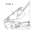
- the proportional mix system 10 ( Figure 2) is mounted within a housing 12 on a well known mobile vehicle 14 which supports an extendable boom 16 for rotation about a vertical axis.
- a hydraulic cylinder 18 raises and lowers the boom, while another hydraulic cylinder (not shown) extends and retracts the boom.
- Long telescopic means in the form of fluid-tight slip tubes of trombones 20, 22 ( Figure 2) extend and retract with the boom through a range of about 12 feet and define extendable portions of the de-icing fluid and water conduits, respectively.
- An operator's basket 24 is mounted on the free end of the boom 16 and has a large O-120 GPM (gallons per minute) (0-546 litres per minute) adjustable spray de-icing nozzle 26 (Figure 2) pivoted to the basket for universal movement, and a smaller hand held 0-30 GPM (0-136 litres per minute) adjustable nozzle 28. Both nozzles 26 and 28 are included in the system 10 and receive fluid from flexible hoses 30, 32 included in the proportional mix system 10 for discharge onto an aircraft A.
- a small hand-held ground nozzle 34 having a capacity of 0-30 GPM (136 litres per minute) is likewise included in the system and receives fluid from a long flexible hose 36 that is preferably mounted on a reel (not shown). Except for the proportional mix system 10, all of the above components are well known in the art, and certain of these components are similar to those illustrated in U.S. Patent Specification No. 3,243,123 to which reference may be made.
- the proportional mix system 10 ( Figure 2) of the preferred embodiment comprises a tank 40 for holding a supply of thixotropic de-icing fluid, a water tank 42 for holding a supply of water, a centrifugal water pump 44, a centrifugal de-icing fluid pump-46, and an engine 48 having its output shaft (not shown) connected to a drive shaft 50 when a mechanical clutch 52 is engaged.
- a water pump belt drive 54 drivingly connects the drive shaft 50 to the shaft 56 of the water pump 44.
- a de-icing fluid pump belt drive 58 connects the drive shaft 50 to an idler pulley 60 journalled on the input shaft 62 of the de-icing fluid pump 46.
- the de-icing fluid pump is driven only when an electric clutch 64 couples the idler pulley 60 to the input shaft 62 of the de-icing fluid pump 46.
- the illustrated clutch is a spring released clutch, which clutch must be electrically engaged to drive the de-icing fluid pump 46 when an electrical coil 64a is energised.
- a de-icing fluid discharge system 65 is illustrated in wide double lines in Figure 2 and will now be described.
- the pump draws fluid from the tank 40 past an open service valve 66 in conduit 68 and into the pump 46 through conduit 70.
- the output on the pump 46 directs the fluid through conduit 72, through check valve 74 and through a de-icing fluid flow switch 76 which closes contacts 194 when the flow is at or above the rate of about three gallons per minute (13.6 litres per minute). If the pressure in conduit 72 exceeds about 90 psi (6.33 Kg/cm 2 ) it actuates and opens normally closed contacts 192 of pressure switch 77.
- the de-icing fluid flows into the extendable slide tube trombone 20 from branch line 78 and out of the trombone 20 through the conduit 80 which splits into two branches.
- One branch communicates with the flexible hose 32 and the hand held nozzle 28.
- the other branch 82 includes one proportioning valve 84 and a check valve 86, which communicates with the flexible hose 30 and the large nozzle 26.
- the proportioning valve 84 forms a part of a proportional mix valve assembly 88 and when fully closed permits substantially 100% hot water to be discharged from nozzle 26.
- De-icing fluid is also supplied to the ground nozzle 34 through conduit 89 having a check valve 90 and a 3-30 gallon per minute (13.6-136 litres per minute) variable flow restrictor or proportioning valve 92 therein.
- a two and one-half gallon per minute (11.4 litres per minute) fixed flow restrictor valve 94 is connected in parallel across the valve 92 with the conduit 89 directing its de-icing fluid to the ground nozzle 34 through the flexible hose 36.
- de-icing or anti-icing operations water must be purged from the water pump 44 and water lines by forcing water out of their components and replacing the water with de-icing fluid as will be fully explained later.
- the de-icing fluid used for purging water flows from conduit 89, into a conduit 96 having a purge valve 100 therein which is illustrated in a position blocking flow therepast but is shifted to a position allowing fluid to flow therethrough into conduit 102 during purging.
- De-icing fluid flows from conduit 102 past check valve 104 and into the water system through conduit 106 for purging water therefrom as will be described.
- conduit 102 When the pressure in conduit 102 exceeds about 50 psi (3.52 Kg/cm 2 ), it opens a pilot pressure operated relief valve 108 and flows through conduit 110 which is connected to conduits 68 and 70 adjacent the inlet end of the de-icing fluid pump.
- a branch conduit 112 is connected in parallel across the flow control switch 76 and check valve 74.
- the conduit 112 has a relief valve 114 therein which is opened by a pressure of about 275 psi (19.33 Kg/cm 2 ) entering pilot line 116 thus preventing the boom from being hydraulically locked by de-icing fluid when all nozzles are closed.
- a water discharge system 120 receives water from the water tank 42 which is drawn by the water pump 44 from the tank 42 through a service valve 122, through a low level flow switch 124, and past a check valve 126.
- the centrifugal water pump provides up to about 120 gallons per minute at 200 psi (546 litres per minute at 14.06 Kg/cm 2 ) and directs the water through a conduit 127 into and through a 3,000,000 British thermal unit per hour (756,000 c/h) water heater 128.
- the water heater 128 heats the water to an operating temperature between about 120°F and 180°F (49°C and 82°C). If the low level flow control switch 124 senses that the tank is empty or the water level in the tank 44 is low, it turns off the heater 128 and turns on a red warning light 130.
- the hot water from the heater 128 flows through conduits 132 and 134, through a flow switch 136 which closes if the rate of flow is about three gallons per minute (13.6 litres per minute) or more.
- the hot water then flows into and through the slip tube trombone 22, through a second ball valve 138 of the proportional mix valve 88, through a check valve 140 and mixes with the cooler thixotropic de-icing fluid from conduit 82 (if the de-icing fluid is being used), prior to being discharged from the nozzle 26 onto the aircraft to de-ice the aircraft.
- hot water from conduit 132 flows through flow switch 142 the contacts of which close when about three gallons per minute (13.6 litres per minute) or more flow through the switch 142.
- the hot water then flows through conduit 144, fixed flow restrictor valve 146, past check valve 148, and mixes with the cooler de-icing fluid prior to being discharged against the aircraft by the lower nozzle 34.
- valve 160 for return to the water tank 42. It will be appreciated that opening of relief valve 156 also prevents hydaulic lock of the water system when all nozzles are closed and the boom and slip tube trombones 20, 22 are retracted.
- water must be purged from the water discharge system 120 to avoid freezing after the de-icing and/or anti-icing operations have been completed and the de-icer is shut down.
- This purging of water is accomplished by shifting de-icing fluid purge valves 100 and 160 into open and closed positions, respectively. With the nozzles 26 and 34 open, the purging de-icing fluid from conduit 106 then forces the water out of the water pump 44, the conduit 127 which extends into and through the water heater 128, conduits 132 and 134, slip tube trombone 22, valves, 138, 140 and then flows out of the nozzle 26.
- de-icing fluid is seen discharging from the nozzle 26, the nozzle is closed and the operator knows that the fluid within these components is de-icing fluid which will not freeze.
- the de-icing fluid likewise purges water from the flow switch 142, conduit 144 for flow out of the system past resistor valve 146, check valve 148 and out of the nozzle 34 which is closed when the de-icing fluid is seen discharging from the nozzle 34. Any water remaining in the water tank 42 is drained by opening a valve 162, and, when desired, the thixotropic de-icing fluid may be drained from the tank 40 by opening the valve 164.
- a low level switch 166 in the de-icing fluid tank 40 is connected to a warning light and power source (not shown) which indicates when the thixotropic level is low and should be replenished.
- the proportional mix valve assembly 88 includes the two proportioning valves 84 and 138 which are connected to a control lever 168 which is pivoted adjacent a quadrant 170 that is marked in approximate percentages of de-icing fluid in the fluid mixture that will be directed against the aircraft by the large nozzle 26.
- the approximate percentages of thixotropic de-icing fluid in hot water is illustrated as 0%, 10%, 30%, and 60%: It will be understood that the percentages are not exact but indicate the approximate percent of de-icing fluid in the fluid mixture that is applied to the aircraft.
- variable flow restrictor valve 92 in the de-icing fluid conduit system associated with the ground nozzle 34 is manually controlled to provide a desired amount of de-icing fluid to the hot water that is sprayed on the aircraft by personnel on the ground. If the adjustable restrictor or proportioning valve 92 is fully closed, the by-pass flow restrictor 94 ensures that about 2 1/2 gallons per minute (11.38 litres per minute) of de-icing fluid will be mixed with water when the ground nozzle 34 is opened.
- the electrical control circuit 172 is operative to cause immediate and reliable disengagement of the clutch 64, thus stopping the de-icing pump 46, when continued driving of the pump would cause detrimental shear to the thixotropic de-icing fluid.
- the control circuit 172 is responsive to the pressure and rate of flow of the de-icing fluid in the de-icing discharge system 65 by means of the pressure switch 77 and the flow switch 76.
- the control circuit 172 also responds to the flow of water in the water discharge system 120 by means of flow switches 126, and 142, and also by the position of the control lever 168 of the proportional mix valve assembly 88.
- the electrical control circuit 172 preferably receives 12 volt direct current from a battery 174 which is charged by the usual engine driven generator (not shown).
- the circuit 172 includes a master switch 176 which when closed starts the engine 48 through conventional engine circuits. Upon engaging the mechanical clutch 52, the engine 48 drives the water pump 44 and provides power to drive the de-icing fluid pump 46 when the electric clutch 64 is engaged. Closing of the master switch 176 also energises the coil of a master relay 178 which completes its circuit to ground 180 thereby closing master relay contact 182 directing current to the coil 184 of clutch relay 186. If clutch relay coil 184 is energised, relay contact 188 closes thereby energising clutch coil 64a. In the preferred illustrated embodiment such energisation is accomplished by grounding the circuit as at 180a. Energisation of clutch coil 64a engages the clutch 64 thus driving the de-icing fluid pump 46.
- the clutch relay coil 184 is energised to engage the clutch 64 in response to several different and independent conditions.
- the clutch 64a is de-energised, the clutch 64 is disengaged thus stopping the de-icing fluid pump 46 to minimize shear damage to the thixotropic de-icing fluid.
- pressure switch 77 closes its electrical switch contact 192 which completes the circuit to ground 180b energising clutch coil 64a and thereby engaging the clutch 64 to drive the de-icing fluid pump 46.
- switch contact 192 opens thus de-energising clutch coil 64a and disengaging clutch 64 provided that another control circuit (to be described) does not energize the clutch relay coil 64a.
- flow switch contact 194 When the rate of flow of de-icing fluid through flow switch 76 is below about three gallons per minute (13.6 litres per minute), flow switch contact 194 remains open and thus the spring-released clutch will remain disengaged and will not drive the de-icing pump 46 provided another control means such as the contact 192 of pressure switch 77 is not closed. When flow through the flow switch exceeds about three gallons per minute (13.6 litres per minute) the switch contact 194 of flow switch 76 closes to ground 180c thus engaging the clutch 64 and driving the de-icing fluid pump 46.
- the lower flow switch 142 closes its switch contact 200 to ground 180e when water flows therethrough at a rate in excess of about three gallons per minute (13.6 litres per minute) thereby energising clutch relay coil 184 and clutch coil 64a which engages the clutch 64 and drives the de-icing fluid pump 46.
- the switch contact 200 of flow switch 142 opens thus disengaging the clutch and stopping the de-icing pump 46 unless the clutch 64 is engaged through another portion of the control circuit.
- the low water level flow switch 124 maintains its switch contact 202 closed if sufficient water is present in the water tank 42 thereby closing a circuit through relay coil 204 to ground 180f which closes relay contact 206. Closed relay contact 206 permits heat energy to be applied to the water heater 128 in a conventional manner.
- the flow through flow switch 124 opens switch contact 202 thus turning off the water heater, and closes a circuit to the "low water” warning light 130.
- the pump 46 is preferably a centrifugal pump having a 0-120 gallon per minute capacity (0-546 litres per minute) and a pressure head of about 200 psi (14.06 Kg/cm 2 ).
- the pressure in the de-icing system will decrease in response to extension of the boom 16 and slip tube trombones 20, 22. This action may decrease the pressure below about 90 psi (6.33 Kg/cm 2 ) in pressure switch 77 so that the clutch 64 will be energised and drive the de-icing pump 46 to fill the expanding trombone 20, but only momentarily.
- the handle 168 When the proportional mix handle 168 is above about the 10% position, the handle 168 allows switch 171 to close. When the nozzle 26 is open enough to cause more than about three gallons per minute (13.6 litres per minute) to flow through the flow switch 136 in the water discharge system 120, switch element 198 will close thereby energising clutch 64 and driving the de-icing fluid pump 46 to provide substantially the percent of de-icing fluid water mix indicated by the position of the proportional mix valve handle 168.
- the ground nozzle 34 operates independently of the position of the proportional mix handle 160.
- a flow of water in excess of about three gallons per minute (13.6 litres per minute) through flow switch 142 closes switch element 200 thus engaging the clutch 64 and driving the de-icing fluid pump 46.
- the proportion of de-icing fluid hot water is controlled by the operator who adjusts the variable flow restrictor valve 92 as desired.
- the fixed flow restrictor valve 94 bypasses about 2 1/2 gpm (11.4 litres per minute) when the nozzle 34 is open.
- water remaining in water pump 44, water tank 42, heater 128 and the remainder of the water discharge system 120 may freeze if the mobile de-icing vehicle 14 is left idle in freezing temperatures.
- the proportional mix handle 168 may be left in any position but preferably at the 0% position so that completion of water purging can be visually detected when substantially pure de-icing fluid is seen discharging from the nozzles 26 and 34. Purging is initiated by shifting purge valves 100, 160 from the illustrated position in Figure 2 to their other positions.
- the pressure acting on pressure valve 77 will be below about 90 psi and switch element 192 will be closed to energise the clutch 64 and drive the de-icing fluid.
- the nozzles 26 and 34 will be closed when de-icing fluid is seen discharging therefrom thus indicating that the water has been purged from the water discharge system 120. Opening the ground nozzle 34 will direct de-icing fluid into water conduit 144 to replace the water with anti-freeze, and low switch contact 200 will be closed at this time to drive the de-icing fluid pump 46 provided three gallons per minute (13.6 litres per minute) flows through flow switch 142.
- the tank 42 is drained by opening the valve 162.
- the proportional mix system and method for applying thixotropic de-icing fluid to aircraft includes a clutch for the de-icing fluid pump that is engaged and disengaged in response to several different flow conditions and pressure conditions within the liquid discharge systems. Also, the clutch is operated in response to the proportion of thixotropic de-icing fluid and hot water directed onto the aircraft during de-icing.
- the control of the de-icing fluid pump minimizes shear and other breakdown of the fluid by driving the de-icing fluid pump only to maintain the de-icing discharge system 65 filled with de-icing fluid at about 90 psi when all nozzles are closed, and to maintain the system 65 filled when the de-icing fluid is being discharged from one or more nozzles.
- the de-icing fluid is unheated until it mixes with hot water adjacent the associated nozzle.
Landscapes
- Engineering & Computer Science (AREA)
- Manufacturing & Machinery (AREA)
- Transportation (AREA)
- Aviation & Aerospace Engineering (AREA)
- Control Of Positive-Displacement Pumps (AREA)
- Special Spraying Apparatus (AREA)
- Buildings Adapted To Withstand Abnormal External Influences (AREA)
Claims (17)
Applications Claiming Priority (2)
| Application Number | Priority Date | Filing Date | Title |
|---|---|---|---|
| US100173 | 1979-12-04 | ||
| US06/100,173 US4333607A (en) | 1979-12-04 | 1979-12-04 | Proportional mix system and method for applying a thixotropic de-icing fluid to an aircraft |
Publications (3)
| Publication Number | Publication Date |
|---|---|
| EP0030454A2 EP0030454A2 (fr) | 1981-06-17 |
| EP0030454A3 EP0030454A3 (en) | 1982-04-21 |
| EP0030454B1 true EP0030454B1 (fr) | 1986-11-05 |
Family
ID=22278453
Family Applications (1)
| Application Number | Title | Priority Date | Filing Date |
|---|---|---|---|
| EP80304366A Expired EP0030454B1 (fr) | 1979-12-04 | 1980-12-03 | Procédé et appareil pour appliquer un fluide dégivrant |
Country Status (4)
| Country | Link |
|---|---|
| US (1) | US4333607A (fr) |
| EP (1) | EP0030454B1 (fr) |
| CA (1) | CA1158135A (fr) |
| DE (1) | DE3071816D1 (fr) |
Families Citing this family (18)
| Publication number | Priority date | Publication date | Assignee | Title |
|---|---|---|---|---|
| DK157064C (da) * | 1981-12-08 | 1990-04-30 | Godtfred Vestergaard | Koeretoej til afisning af flyvemaskiner |
| US4872501A (en) * | 1986-03-17 | 1989-10-10 | Fmc Corporation | Heat exchanger for mobile aircraft deicing machine and method of use |
| US4898330A (en) * | 1987-09-28 | 1990-02-06 | Betchan Jerry L | Portable deicer sprayer |
| DK269888A (da) * | 1988-05-17 | 1989-11-18 | Godtfred Vestergaard | Udfoldelig ledstandsmekamisme |
| FR2636020B1 (fr) * | 1988-09-07 | 1991-02-08 | Charton Alain | Unite mobile de degivrage d'aeronefs |
| US5028017A (en) * | 1989-08-08 | 1991-07-02 | Federal Express Corporation | Mobile system for deicing aircraft |
| US5190249A (en) * | 1989-09-25 | 1993-03-02 | Zwick Energy Research Organization, Inc. | Aircraft deicer fluid heating and propulsion system |
| US5096145A (en) * | 1990-02-05 | 1992-03-17 | Fmc Corporation | Aircraft deicing apparatus and method |
| US5242133A (en) * | 1990-12-28 | 1993-09-07 | Zwick Eugene B | Method and apparatus for heating and delivering deicing fluids |
| AT1332U1 (de) * | 1996-06-13 | 1997-03-25 | Zellinger Gmbh | Waschgerät, insbesondere für düsenaggregate von flugzeugen |
| US6047926A (en) | 1996-06-28 | 2000-04-11 | Alliedsignal Inc. | Hybrid deicing system and method of operation |
| US6360992B1 (en) | 1996-06-28 | 2002-03-26 | Honeywell International Inc. | Hybrid deicing system and method of operation |
| FI108278B (sv) * | 1999-10-29 | 2001-12-31 | Marioff Corp Oy | Drivkälla för leverans av vattenbaserad vätska till ett system, samt brandsläckningsinstallation |
| CA2356066A1 (fr) | 2001-08-28 | 2003-02-28 | John M. Goston | Dispositifs pour le degivrage et l'antigivrage d'aeronefs |
| WO2006113877A2 (fr) * | 2005-04-20 | 2006-10-26 | Lugg Richard H | Aeronef vtol hybride a reaction/electrique |
| US7934680B2 (en) * | 2007-05-21 | 2011-05-03 | Global Ground Support, Llc | Apparatus and method for blending fluids |
| CN101628546B (zh) * | 2009-08-12 | 2012-08-22 | 中原特种车辆有限公司 | 燃气减压系统及天然气清蜡车 |
| US10882608B2 (en) | 2018-03-22 | 2021-01-05 | The Boeing Company | Hydraulic system for a vehicle and method of using the same |
Family Cites Families (9)
| Publication number | Priority date | Publication date | Assignee | Title |
|---|---|---|---|---|
| GB822811A (en) * | 1956-02-14 | 1959-11-04 | British Europ Airways Corp | Improved apparatus for de-frosting the external surfaces of aircraft or other surfaces needing similar treatment |
| US2938509A (en) * | 1958-08-14 | 1960-05-31 | Motocycles Et Automobiles Soc | Mixers for two liquids, such as those for supplying engines with a mixture of fuel and lubricant |
| US3243123A (en) * | 1963-02-21 | 1966-03-29 | Fmc Corp | Spraying apparatus |
| DE1266139B (de) * | 1964-04-22 | 1968-04-11 | Bernhard Schulze Eckel | Anlage zum Enteisen groesserer Objekte, insbesondere von Fahr- und Flugzeugen |
| BE804040A (fr) * | 1972-08-28 | 1973-12-17 | Dustbane Enterprises Ltd | Appareil pour le degivrage d'avions |
| US4118151A (en) * | 1974-04-03 | 1978-10-03 | Tokico Ltd. | Pump device |
| US4032090A (en) * | 1975-07-21 | 1977-06-28 | Thornton Trump Walter E | Method for deicing aircraft |
| US4073437A (en) * | 1976-06-11 | 1978-02-14 | Thorton Trump Walter Edmond | Conversion package for aircraft de-icing machines |
| US4191348A (en) * | 1977-11-10 | 1980-03-04 | Holwerda-Huizenga Co. | Deicing system |
-
1979
- 1979-12-04 US US06/100,173 patent/US4333607A/en not_active Expired - Lifetime
-
1980
- 1980-11-28 CA CA000365700A patent/CA1158135A/fr not_active Expired
- 1980-12-03 DE DE8080304366T patent/DE3071816D1/de not_active Expired
- 1980-12-03 EP EP80304366A patent/EP0030454B1/fr not_active Expired
Also Published As
| Publication number | Publication date |
|---|---|
| DE3071816D1 (en) | 1986-12-11 |
| US4333607A (en) | 1982-06-08 |
| EP0030454A3 (en) | 1982-04-21 |
| EP0030454A2 (fr) | 1981-06-17 |
| CA1158135A (fr) | 1983-12-06 |
Similar Documents
| Publication | Publication Date | Title |
|---|---|---|
| US4333607A (en) | Proportional mix system and method for applying a thixotropic de-icing fluid to an aircraft | |
| US5096145A (en) | Aircraft deicing apparatus and method | |
| US5028017A (en) | Mobile system for deicing aircraft | |
| US4191348A (en) | Deicing system | |
| US7934680B2 (en) | Apparatus and method for blending fluids | |
| US4124039A (en) | Pipe thawing machine | |
| US4371096A (en) | Control apparatus for pressurized gas/liquid systems | |
| US4519213A (en) | Ambient air heated electrically assisted cryogen vaporizer | |
| US5615559A (en) | Method and apparatus for recirculating product in a refrigeration system | |
| US4244403A (en) | Apparatus for transferring liquid between a reservoir and a mobile tank truck | |
| US4573802A (en) | Deicing method and apparatus | |
| US6093247A (en) | Distribution system for applying a viscous material to a roof | |
| GB2091911A (en) | Automatic control of liquid supply | |
| CA2356066A1 (fr) | Dispositifs pour le degivrage et l'antigivrage d'aeronefs | |
| US3720226A (en) | Vehicular mounted wash apparatus | |
| US12264678B2 (en) | Fuel pump driven by a variable displacement motor for aerial refueling operation | |
| EP2747908B1 (fr) | Appareil de nettoyage haute pression | |
| CA2564016C (fr) | Systeme de regulation de pulverisation incorporee dans des dispositifs anti-givre d'aeronefs | |
| US2322577A (en) | Hydraulic clutch structure | |
| DE2904566C2 (de) | Anlage zur Beheizung der Waschflüssigkeit einer Scheibenwaschanlage und/oder der Scheinwerferwaschanlage | |
| FI76506B (fi) | Anordning foer avisning av isynnerhet ytterytor hos flygplan. | |
| GB2215491A (en) | Pump apparatus for discharging liquid | |
| RU132787U1 (ru) | Устройство для разогрева и слива нефти и нефтепродуктов из емкости (варианты) | |
| KR200212426Y1 (ko) | 염화칼슘액 살포장치 | |
| CN214331029U (zh) | 液压撒布机的液压回路 |
Legal Events
| Date | Code | Title | Description |
|---|---|---|---|
| PUAI | Public reference made under article 153(3) epc to a published international application that has entered the european phase |
Free format text: ORIGINAL CODE: 0009012 |
|
| AK | Designated contracting states |
Designated state(s): BE DE FR GB IT NL |
|
| PUAL | Search report despatched |
Free format text: ORIGINAL CODE: 0009013 |
|
| AK | Designated contracting states |
Designated state(s): BE DE FR GB IT NL |
|
| 17P | Request for examination filed |
Effective date: 19820928 |
|
| GRAA | (expected) grant |
Free format text: ORIGINAL CODE: 0009210 |
|
| AK | Designated contracting states |
Kind code of ref document: B1 Designated state(s): BE DE FR GB IT NL |
|
| ET | Fr: translation filed | ||
| REF | Corresponds to: |
Ref document number: 3071816 Country of ref document: DE Date of ref document: 19861211 |
|
| ITF | It: translation for a ep patent filed | ||
| PLBE | No opposition filed within time limit |
Free format text: ORIGINAL CODE: 0009261 |
|
| STAA | Information on the status of an ep patent application or granted ep patent |
Free format text: STATUS: NO OPPOSITION FILED WITHIN TIME LIMIT |
|
| 26N | No opposition filed | ||
| PGFP | Annual fee paid to national office [announced via postgrant information from national office to epo] |
Ref country code: FR Payment date: 19901116 Year of fee payment: 11 |
|
| PGFP | Annual fee paid to national office [announced via postgrant information from national office to epo] |
Ref country code: DE Payment date: 19901128 Year of fee payment: 11 |
|
| PGFP | Annual fee paid to national office [announced via postgrant information from national office to epo] |
Ref country code: BE Payment date: 19901129 Year of fee payment: 11 |
|
| PGFP | Annual fee paid to national office [announced via postgrant information from national office to epo] |
Ref country code: GB Payment date: 19901130 Year of fee payment: 11 |
|
| ITTA | It: last paid annual fee | ||
| PGFP | Annual fee paid to national office [announced via postgrant information from national office to epo] |
Ref country code: NL Payment date: 19901231 Year of fee payment: 11 |
|
| PG25 | Lapsed in a contracting state [announced via postgrant information from national office to epo] |
Ref country code: GB Effective date: 19911203 |
|
| PG25 | Lapsed in a contracting state [announced via postgrant information from national office to epo] |
Ref country code: BE Effective date: 19911231 |
|
| BERE | Be: lapsed |
Owner name: FMC CORP. Effective date: 19911231 |
|
| PG25 | Lapsed in a contracting state [announced via postgrant information from national office to epo] |
Ref country code: NL Effective date: 19920701 |
|
| GBPC | Gb: european patent ceased through non-payment of renewal fee | ||
| NLV4 | Nl: lapsed or anulled due to non-payment of the annual fee | ||
| PG25 | Lapsed in a contracting state [announced via postgrant information from national office to epo] |
Ref country code: FR Effective date: 19920831 |
|
| PG25 | Lapsed in a contracting state [announced via postgrant information from national office to epo] |
Ref country code: DE Effective date: 19920901 |
|
| REG | Reference to a national code |
Ref country code: FR Ref legal event code: ST |